![]() 2006-2022 Kawasaki Vulcan 900 Power Commander 6
2006-2022 Kawasaki Vulcan 900 Power Commander 6
Instruction Manual
2006-2022 Kawasaki Vulcan 900 Power Commander 6
POWER COMMANDER 6
Installation Guide for: PC6-17032
Model coverage: 2006-2022 Kawasaki Vulcan 900
PARTS LIST
1 POWER COMMANDER 6
1 INSTALLATION GUIDE
1 USB CABLE 2 DYNOJET DECALS
2 POWER COMMANDER DECALS
2 VELCRO STRIPS
1 ALCOHOL SWAB
PLEASE READ ALL DIRECTIONS BEFORE STARTING INSTALLATION.
THE IGNITION MUST BE TURNED OFF BEFORE INSTALLATION.
IPC6-17032.01
INPUT ACCESSORY GUIDE
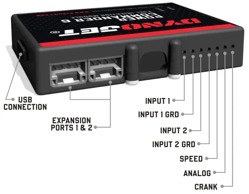
OPTIONAL ACCESSORY INPUTS
Map
(Input 1 or 2) The PC6 has the ability to hold 2 different base maps. You can switch on the fly between these two base maps when you hook up a switch to the MAP inputs. You can use any open/close type switch. The polarity of the wires is not important.
Shifter
(Input 1 or 2) Used for clutch-less full throttle upshifts. Insert the wires from the Dynojet quick shifter into either Input 1 or Input 2. The polarity of the wires is not important. Set to Input 2 by default.
Speed
Not needed on Harley applications as the speed signal wire is built into the main wiring harness of the PC6.
Analog
This input is for a 0-5v signal such as engine temp, boost, etc. Once this input is established you can alter your fuel curve based on this input in the Power Core software.
Launch
You can connect a wire to either Input 1 or Input 2 and then the other end to a switch. This switch when engaged (continuity) will only allow the RPM to be raised to a certain limit (set in the software). When released, you will have full RPM.
WIRE CONNECTIONS
To input wires into the PC6 first remove the rubber plug on the backside of the unit and loosen the screw for the corresponding input. Using a 22-24 gauge wire, strip about 10mm from its end. Push the wire into the hole of the PC6 until is stops and then tighten the screw. Make sure to reinstall the rubber plug.
NOTE: If you tin the wires with solder it will make inserting them easier.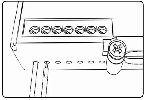 2 2006-2022 KAWASAKI VULCAN 900
INSTALLING THE POWER COMMANDER 6
- Remove the seat. Remove the fuel tank
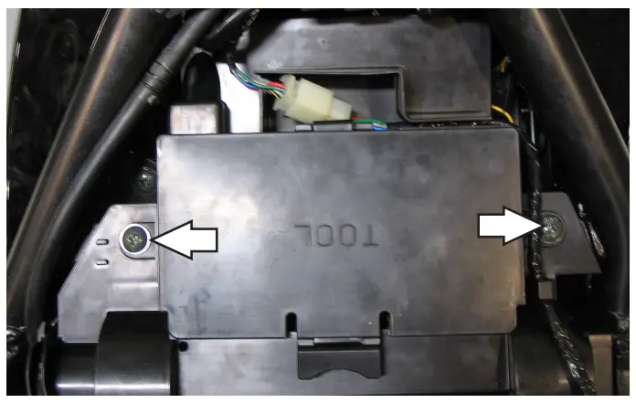
- Remove the battery cover by removing the two screws.”

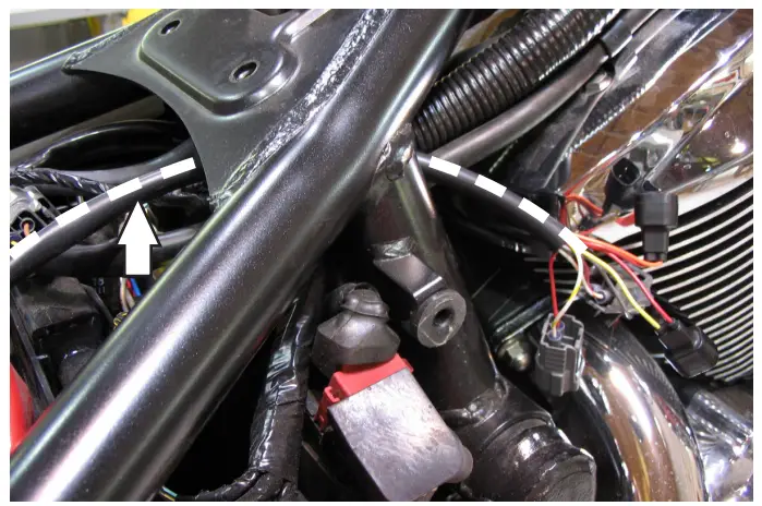
- Lay the PC6 near the battery temporarily. Route the PC6 under the frame and route along side the stock harness towards the throttle bodies.

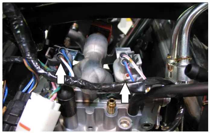
- Unplug the stock wiring harness from both of the fuel injectors at the top of the throttle bodies.

- Plug the PC6 harness in-line of the stock fuel injectors and the wiring harness. Connect the ORANGE colored PC6 wires to the front cylinder.
Note: Hoses were disconnected for picture clarity.
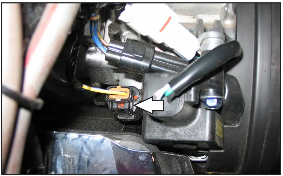
- Locate the Throttle Position Sensor connector. Unplug this connector. This connector is located on the right side of the bike behind the air box.
- Plug the 3-pin connectors from the PC6 in-line of the stock wiring harness and TPS.

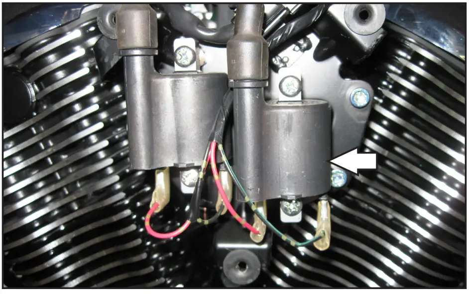
- Remove the cosmetic cover on the left side of the engine.
- Locate the stock ignition coils on the left side of the engine.

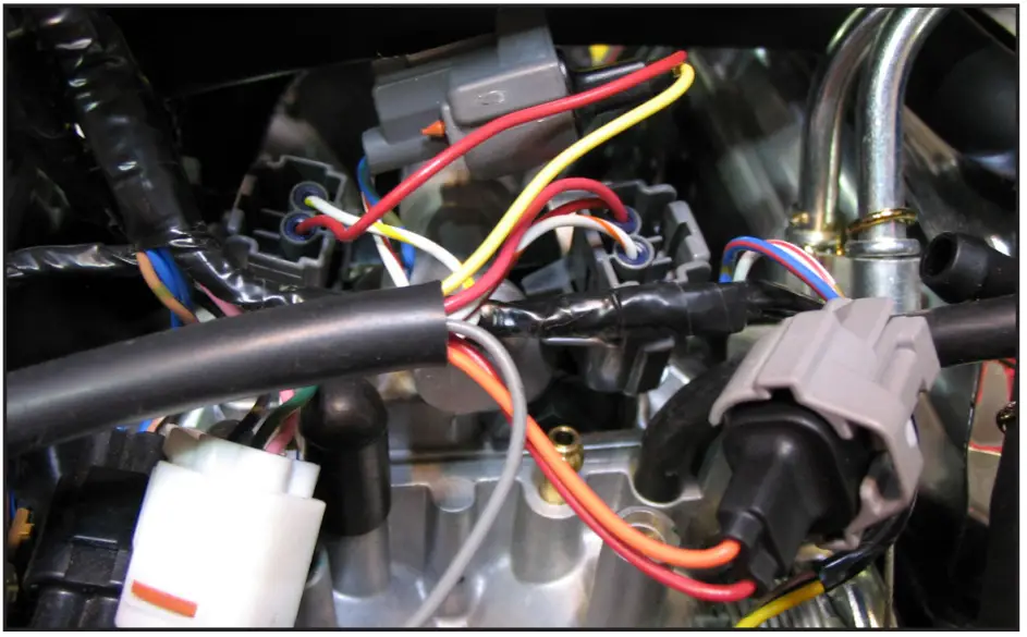
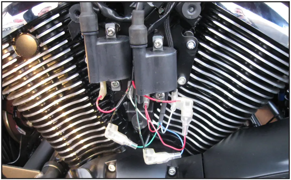
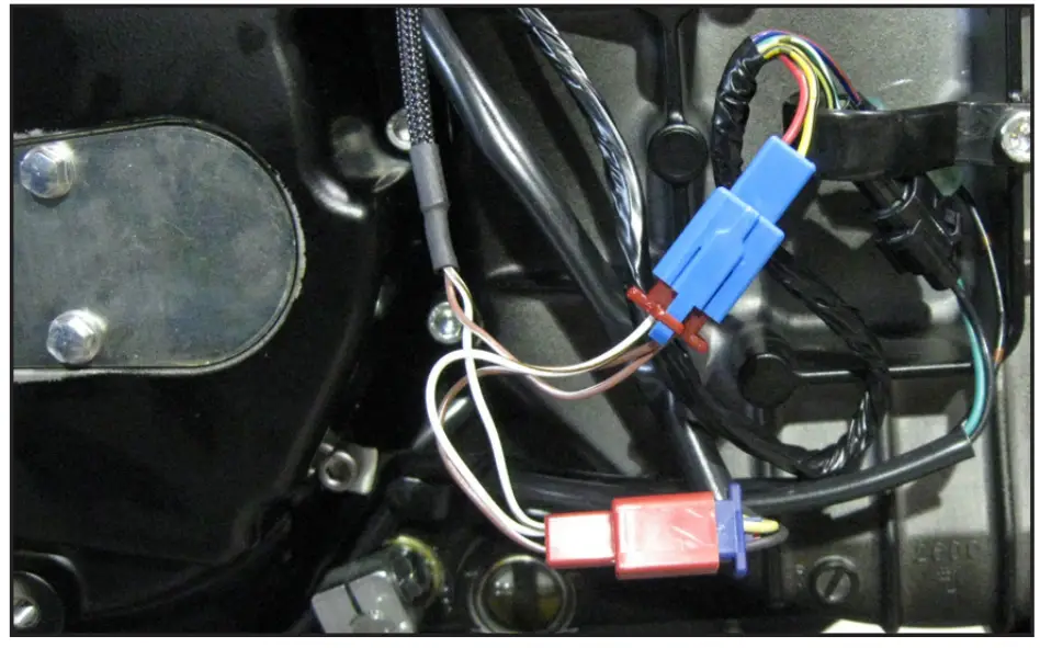
- Plug the PC6 coil connectors in-line of the stock wiring harness and Ignition coils. Plug the PC6 connectors with GREEN colored wires in-line of the coil and the stock BLACK/ORANGE wire.
Plug the PC6 connectors with BLUE colored wires in-line of the coil and the stock BLACK/GREEN wire.
Plug the PC6 connectors with RED colored wires in-line of the coil and the stock RED wire (does not matter which one).
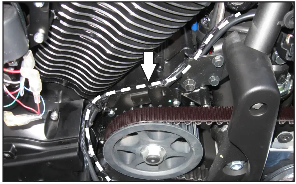
- Remove the front pulley cover on the left side of the engine.
- Route the RED connectors from the PC6 down the left side of the engine following the stock wiring harness.

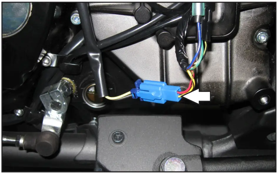
- Unplug the stock crank sensor connector. This is a BLUE 2 pin connector.

- Plug the RED connectors from the PC6 in-line of the stock crank sensor and wiring harness .
- Reinstall engine covers.
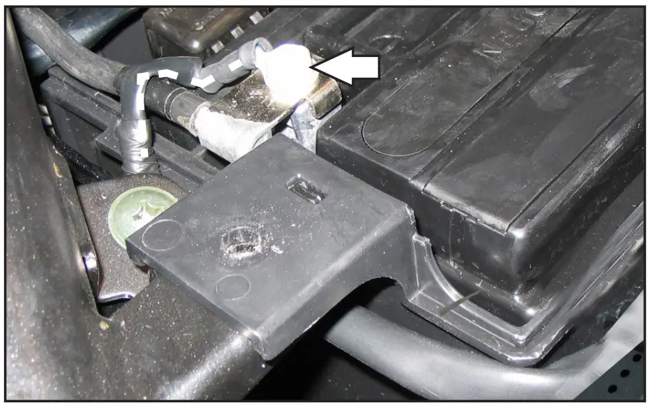
- Install the PC6 to the rear of the battery box. Make sure the PC6 is mounted down about 2″ from the top of the battery box to clear the swingarm.

- Secure the ground eyelet of the PC6 wiring harness to the negative terminal of the bike’s battery.
- Reinstall the battery cover making sure the PC6 harness does not get damaged.

- Reinstall the seat and fuel tank.
Download the latest map files from our web site at dynojet.com/tunes.
Optional Inputs:
Speed Input – Light GREEN/RED wire at ECU.
Temperature Input – ORANGE wire.
12v Source for Autotune – RED wire of 6-pin connector for tail light.![]()
2191 MENDENHALL DRIVE, NORTH LAS VEGAS, NV 89081
– 800-992-4993
– DYNOJET.COM
© 2006-2022 DYNOJET RESEARCH ALL RIGHTS RESERVED


