![]() Install guide for: PC6-17042
Install guide for: PC6-17042
2012-2019 Kawasaki
EX650 POWER COMMANDER 6
Installation Guide
Kawasaki EX650 POWER COMMANDER 6
Model coverage:
2012-2019 Kawasaki EX650 / ER6n
2012-2014 Kawsaki Versys 650
PARTS LIST
| 1 POWER COMMANDER 6 | 2 POWER COMMANDER DECALS |
| 1 INSTALLATION GUIDE | 2 VELCRO STRIPS |
| 1 USB CABLE | 1 ALCOHOL SWAB |
| 2 DYNOJET DECALS | 1 EO LABEL |
PLEASE READ ALL DIRECTIONS BEFORE STARTING INSTALLATION.
THE IGNITION MUST BE TURNED OFF BEFORE INSTALLATION.
x PC6-17042.01
INPUT ACCESSORY GUIDE
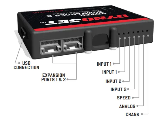
OPTIONAL ACCESSORY INPUTS
| Map | (Input 1 or 2) The PC6 has the ability to hold 2 different base maps. You can switch on the fly between these two base maps when you hook up a switch to the MAP inputs. You can use any open/close type switch. The polarity of the wires is not important. |
| Shifter | (Input 1 or 2) Used for clutch-less full-throttle upshifts. Insert the wires from the Dynojet quick shifter into either Input 1 or Input 2. The polarity of the wires is not important. Set to Input 2 by default. |
| Speed | If your application has a speed sensor then you can tap into the signal side of the sensor and run a wire into this input. This will allow you to calculate gear position in the Control Center Software. Once gear position is set up you can alter your map based on gear position and setup gear-dependent kill times when using a quick-shifter. |
| Analog | This input is for a 0-5v signal such as engine temp, boost, etc. Once this input is established you can alter your fuel curve based on this input in the Power Core software. |
| Launch | You can connect a wire to either Input 1 or Input 2 and then the other end to a switch. This switch when engaged (continuity) will only allow the RPM to be raised to a certain limit (set in the software). When released, you will have full RPM. |
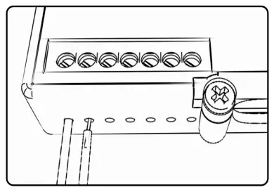
WIRE CONNECTIONS
To input wires into the PC6 first remove the rubber plug on the backside of the unit and loosen the screw for the corresponding input. Using a 22-24 gauge wire, strip about 10mm from its end. Push the wire into the hole of the PC6 until it stops and then tightens the screw. Make sure to reinstall the rubber plug.
NOTE: If you tin the wires with solder it will make inserting them easier.
2 12-19 KAWASAKI NINJA 650 / VERSYS
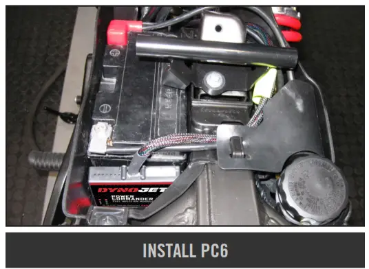
INSTALLING THE POWER COMMANDER 6
- Remove the plastic cover at the front of the fuel tank, the seat, the fuel tank, the airbox, the left side mid-fairing, and the two plastic side covers that are rear of the mid fairings and covering the footpeg brackets.
There is a single Allen bolt clamping the airbox to the throttle bodies that can be accessed from the left side of the bike. - Use the supplied alcohol swab and velcro to secure the PC6 module in the battery compartment to the rear of the battery.

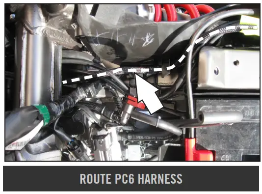
- Route the PC6 harness alongside the factory wiring on the right-hand side of the bike, through the hole in the center of the frame, and up towards the throttle bodies)

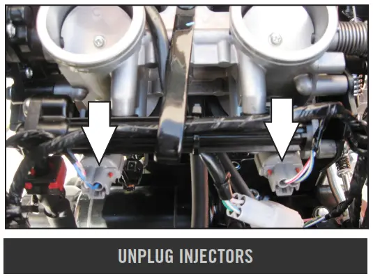
- Unplug the stock wiring harness from the fuel injectors.

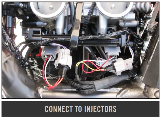
- Plug the PC6 connectors in line with the stock wiring harness and fuel injector for both cylinders (Fig. D).
Plug the PC6 connectors with ORANGE colored wires to the left cylinder.
Plug the PC6 connectors with YELLOW colored wires into the right cylinder.
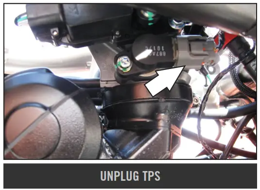
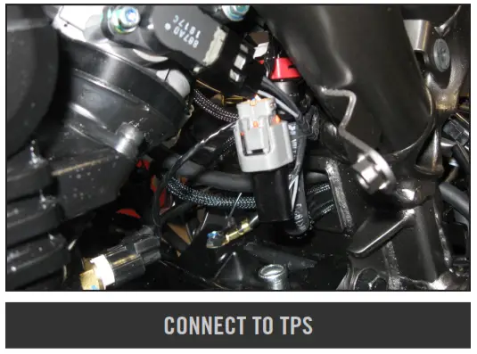
- Locate and unplug the stock wiring harness from the throttle Position Sensor on the left-hand side of the bike’s throttle bodies.

- Plug the PC6 wiring harness in line with the stock wiring harness and the TPS.

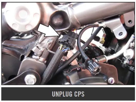
- Locate and unplug the bike’s Crank Position Sensor connectors on the right-hand side of the bike.
This is a BLACK 3-pin connector near the idle adjustment knob.
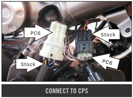
- Plug the PC6 connectors in line with the stock Crank Position Sensor connectors.

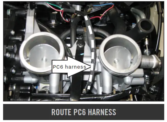
- Route the remainder of the PC6 wiring harness with the coil connectors under the fuel rail, in between the throttle bodies, and up towards the coil sticks.

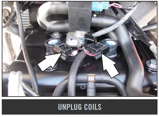
- Unplug the stock wiring harness from the coil sticks.

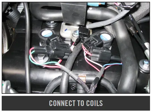
- Plug the PC6 wiring harness in line with the stock wiring harness and the coil sticks.
Plug the PC6 connectors with GREEN colored wires to the left cylinder.
Plug the PC6 connectors with BLUE-colored wires into the right cylinder.
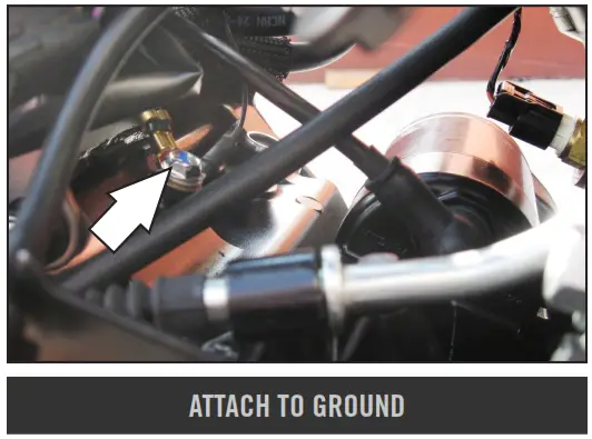
- Secure the ground eyelet of the PC6 wiring harness to the ground bolt on top of the engine case and rear of the starter.
- Make sure the wiring harness is free of any hot or moving parts, and reinstall the airbox, fuel tank, seat, and body panels.
- Affix the supplied CARB E.O. label to a conspicuous area. Next to the original emissions label is the preferred location. Make sure to clean the surface before attaching.

Optional inputs:
Speed – YELLOW wire of 3-pin BLACK connector from c/s sprocket (YEL-PINK-BLK)
Engine Temperature – ORANGE wire of cylinder temp sensor
12v source for Auto-tune – the RED wire of the 3-pin connector for the tail light – under the seat
6 12-19 KAWASAKI NINJA 650 / VERSYS
PUSH THE LIMIT
© 2012-2022 DYNOJET RESEARCH ALL RIGHTS RESERVED
2191 MENDENHALL DRIVE, NORTH LAS VEGAS, NV 89081 – 800-992-4993 – DYNOJET.COM


