![]() 2101579COM Beaumont 20 ft x 12 ft Light Brown All Cedar Wooden Pergola
2101579COM Beaumont 20 ft x 12 ft Light Brown All Cedar Wooden Pergola
Instruction Manual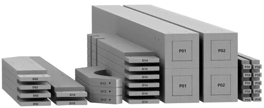
PRE-ASSEMBLY STEP 1 – SORTING PARTS
It is critical for ease of assembly that you take the time to sort and organize the wood
and hardware.
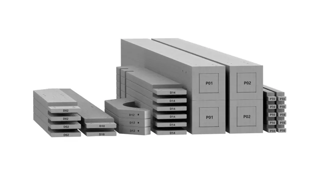
WOOD PARTS:
- Organize wood parts by the three-digit, alpha-numeric number stamped on each board (ex. P0O1).
- If there are multiple boards with the same stamped number, stack those pieces together.
- Stamps can be found on the flat surface of the boards or on the end of the boards.
- Allow yourself plenty of room – the wood pieces can take up a significant amount of space.
NOTE: CARTONS ARE NOT ORGANIZED BY BOARD NUMBER.
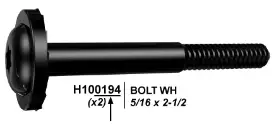
HARDWARE PARTS
- We recommend that you have a separate table to organize the hardware.
- Hardware bags are printed with a seven-digit, alpha-numeric part number.
- You can organize your hardware by part number or group by hardware type (i.e. bolts, nuts, etc.).
- During assembly you only need to reference the last four digits of the number.
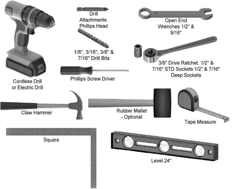
PRE-ASSEMBLY STEP 2 – TOOLS REQUIRED
PRE-ASSEMBLY STEP 3 – CHOOSE YOUR ASSEMBLY METHOD
There are several types of assembly instructions available to you.
- Printed Assembly Manual included with your set
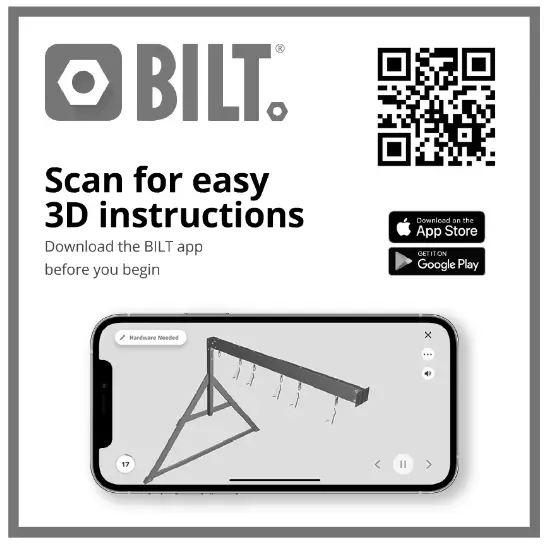
- BILT APP – 3D interactive instructions
- Combination of the Printed Manual and BILT APP (Note: Step numbers can differ between the two methods)
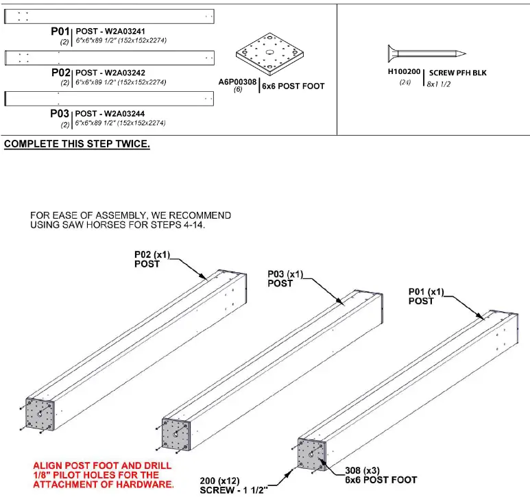
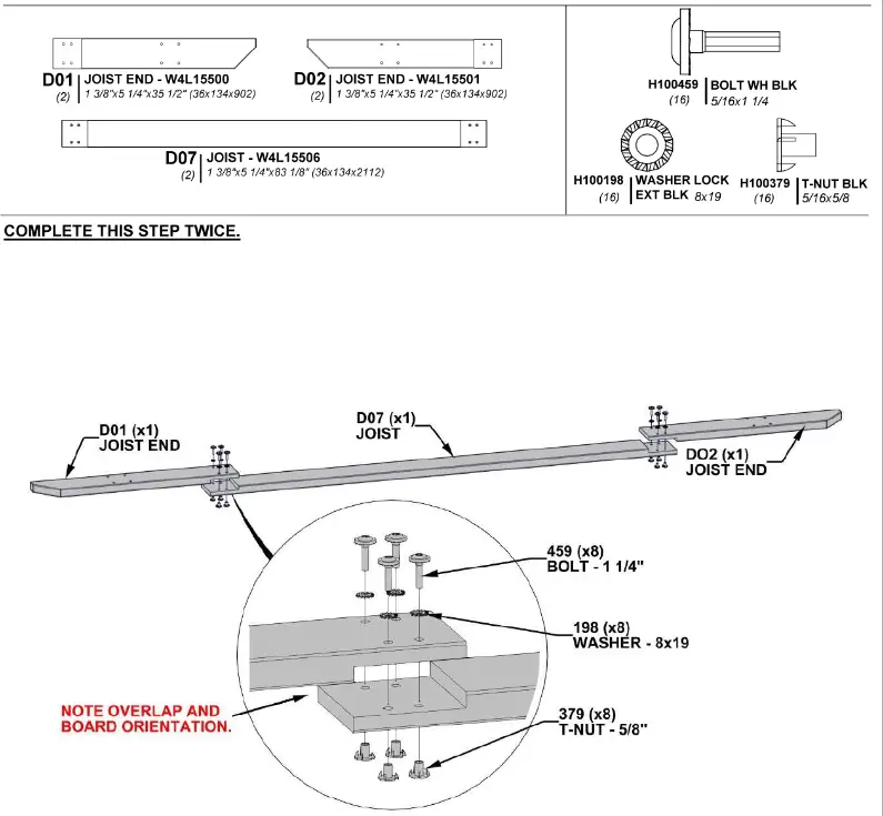
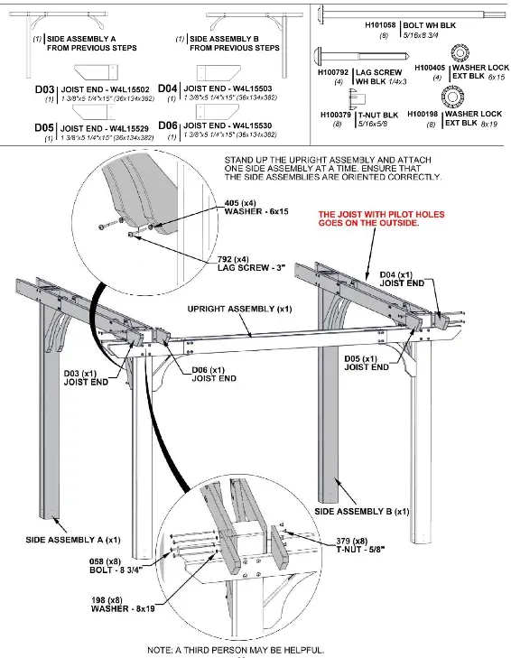
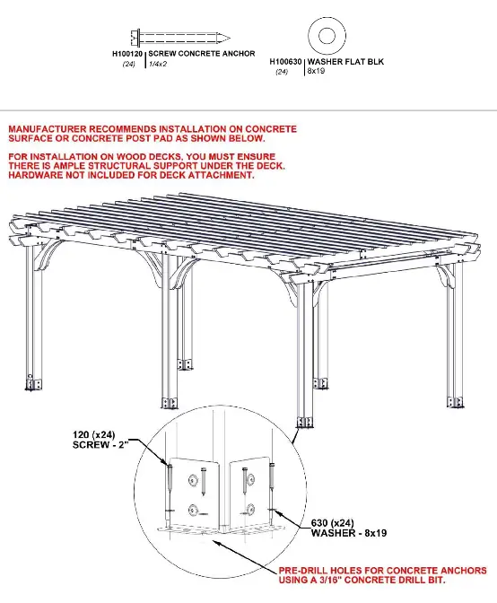
STEP 4 – PERGOLA ASSEMBLY
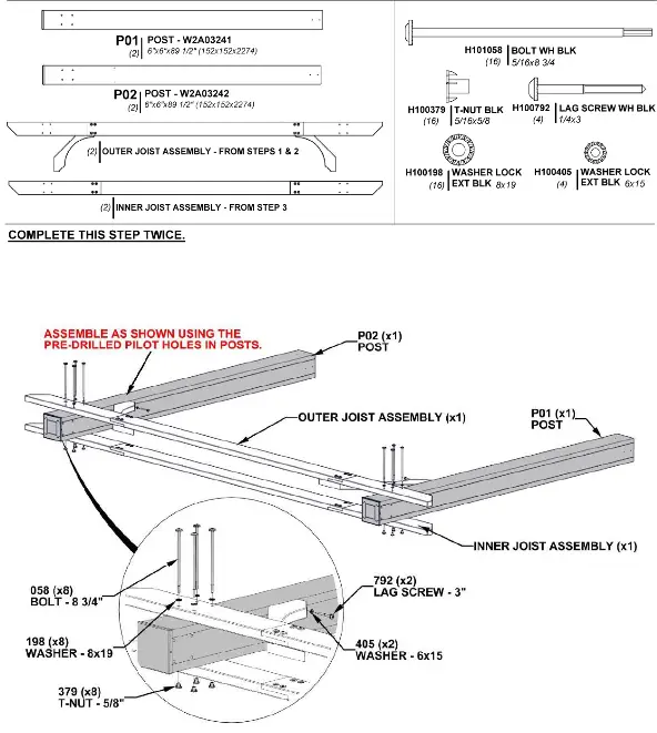
STEP 5 – PERGOLA ASSEMBLY
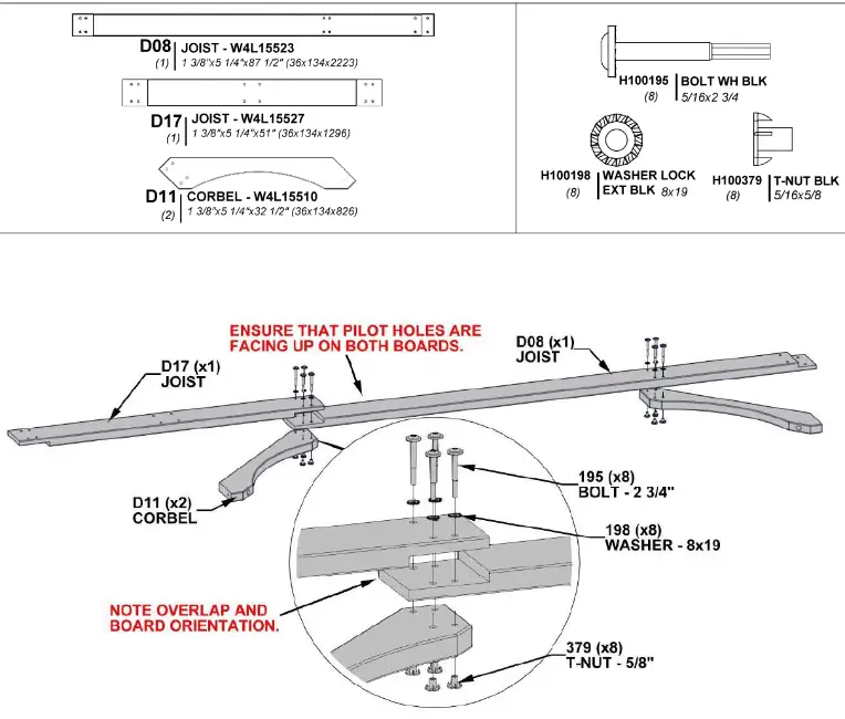
STEP 6 – PERGOLA ASSEMBLY
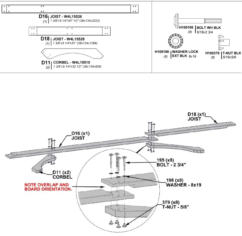
STEP 7 – PERGOLA ASSEMBLY
STEP 8 – PERGOLA ASSEMBLY
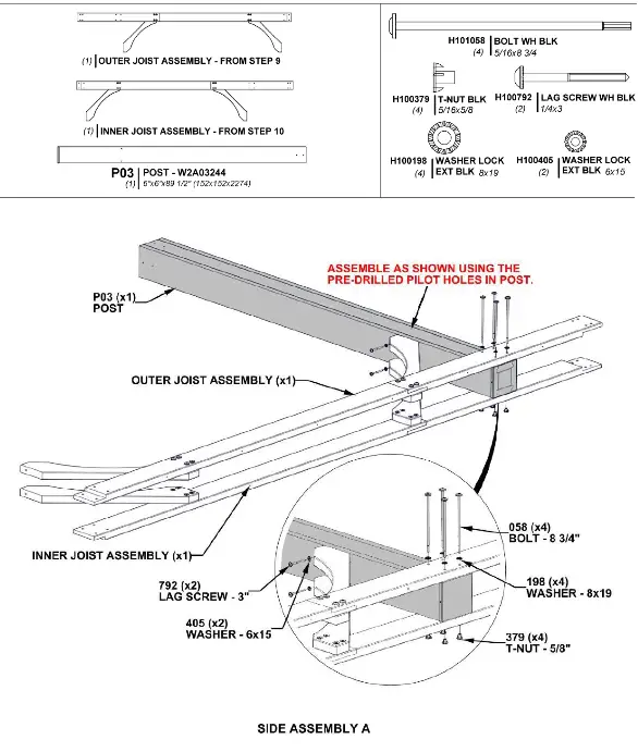
STEP 9 – PERGOLA ASSEMBLY
STEP 10 – PERGOLA ASSEMBLY
STEP 11 – PERGOLA ASSEMBLY
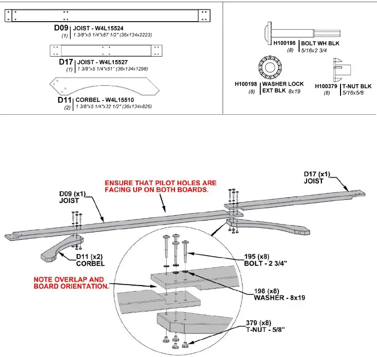
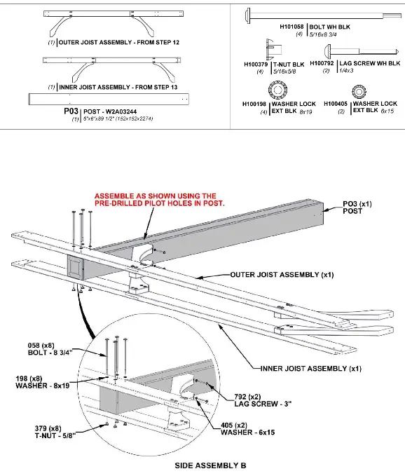
STEP 12 – PERGOLA ASSEMBLY
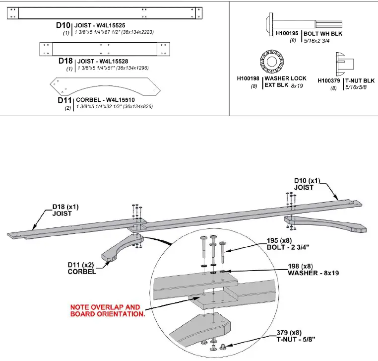
STEP 13 – PERGOLA ASSEMBLY
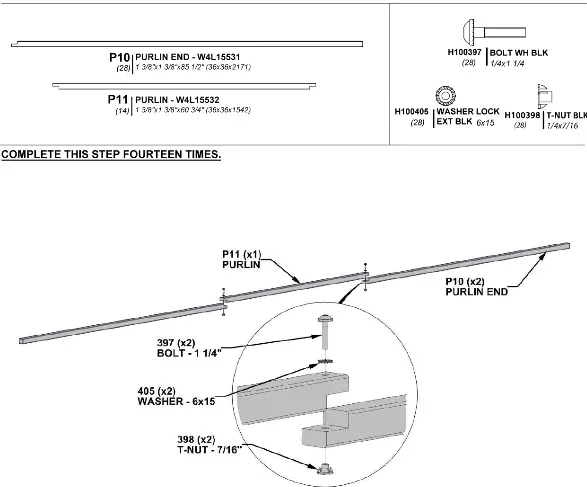
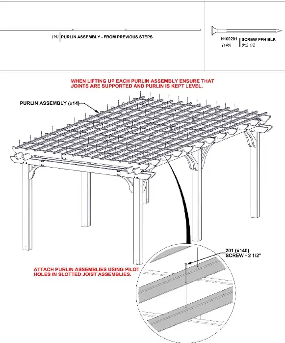
STEP 14 – PERGOLA ASSEMBLY
STEP 15 – PERGOLA ASSEMBLY
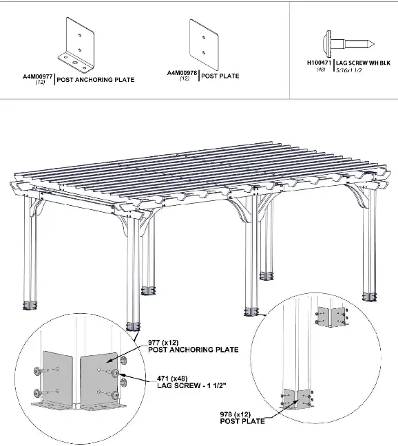
STEP 16 A – PERGOLA ASSEMBLY

STEP 16 B – PERGOLA ASSEMBLY
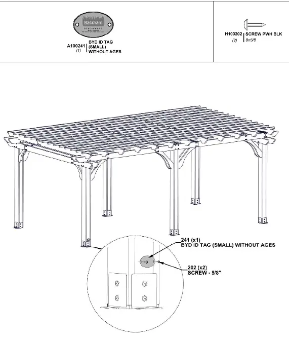
STEP 17 – PERGOLA ASSEMBLY
STEP 18 – PERGOLA ASSEMBLY
STEP 19 – PERGOLA ASSEMBLY
STEP 20 – PERGOLA ASSEMBLY
STEP 21 – PERGOLA ASSEMBLY
STEP 22 – PERGOLA ASSEMBLY
STEP 23 – PERGOLA ASSEMBLY
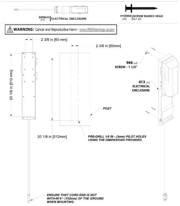
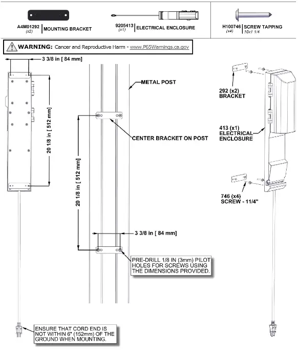
ELECTRICAL ENCLOSURE
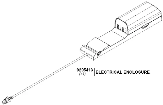
FOR ELECTRICAL ENCLOSURE INSTALLATION REFER TO ASSEMBLY INSTRUCTIONS THAT COME PACKAGED WITH THE ELECTRICAL ENCLOSURE KIT. INSTALL ON ANY POST THAT IS DESIRED. FOLLOW DIRECTIONS FOR PROPER INSTALLATION.
FCC MARKING
This device complies with part 15 of the FCC Rules. Operation is subject to the following two conditions: (1) This device may not cause harmful interference, and (2) this device must accept any interference received, including interference that may cause undesired operation.
FCC INSTRUCTIONS
CAUTION: Changes or modifications not expressly approved by the party responsible for compliance could void the user’s authority to operate the equipment.
For a Class B digital device or peripheral, the instructions furnished the user shall include the following or similar statement, placed in a prominent location in the text of the manual:
Note: This equipment has been tested and found to comply with the limits for a Class B digital device, pursuant to part 15 of the FCC Rules. These limits are designed to provide reasonable protection against harmful interference in a residential installation. This
equipment generates, uses and can radiate radio frequency energy and, if not installed and used in accordance with the instructions, may cause harmful interference to radio communications. However, there is no guarantee that interference will not occur in a
particular installation. If this equipment does cause harmful interference to radio or television reception, which can be determined by turning the equipment off and on, the user is encouraged to try to correct the interference by one or more of the following
measures:
- Reorient or relocate the receiving antenna.
- Increase the separation between the equipment and receiver.
- Connect the equipment into an outlet on a circuit different from that to which the receiver is connected.
- Consult the dealer or an experienced radio/TV technician for help.
![]()
![]() Model # 9205413
Model # 9205413
Metal Post Mounting Instructions![]() MANUFFATURED BY:
MANUFFATURED BY:
3305 Airport Drive
Pittsburg, KS 66762
800-856-4445


