Hanwha Techwin SBO-147B Bullet Backbox Instruction Manual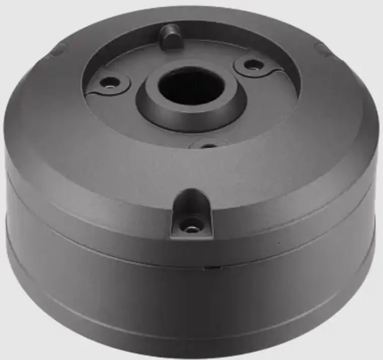
Package
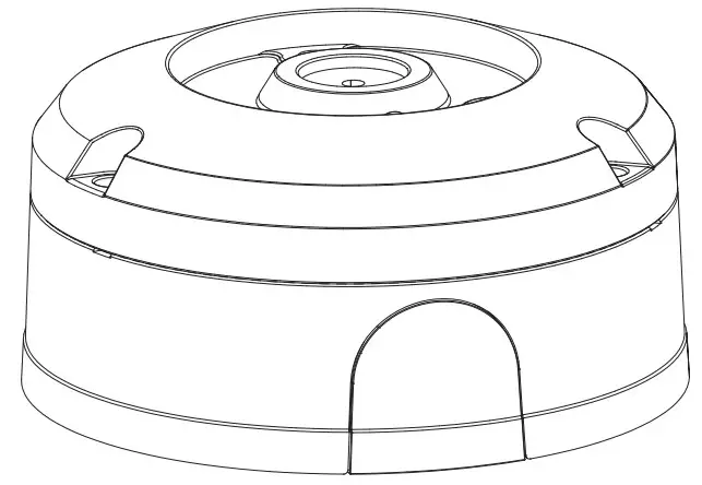
- BACK BOX

- Manual

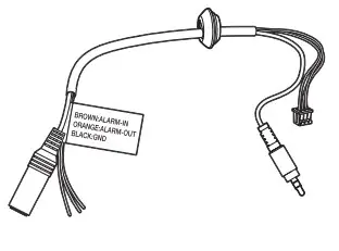
- Audio/Alarm cable

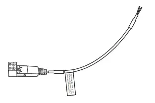
- Power Cable

- Gasket

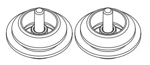
- Cable bush / 2EA

- Cap Installer

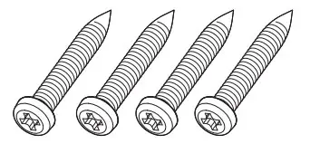
- Tapping Screws (M5 x L30) / 4EA

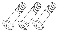
- Machine Screws (M5xL14.5) / 3EA


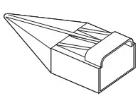
Product Overview
This product is an adapter used in installation that provides a space to install a bullet camera and connect cables (for compatible models, please visit our website).
Installation Precautions
- Install the product in a place that can sufficiently withstand at least 4 times the weight of the SBO-147B camera.
- If installing it outdoors, use fastening parts made of stainless steel .
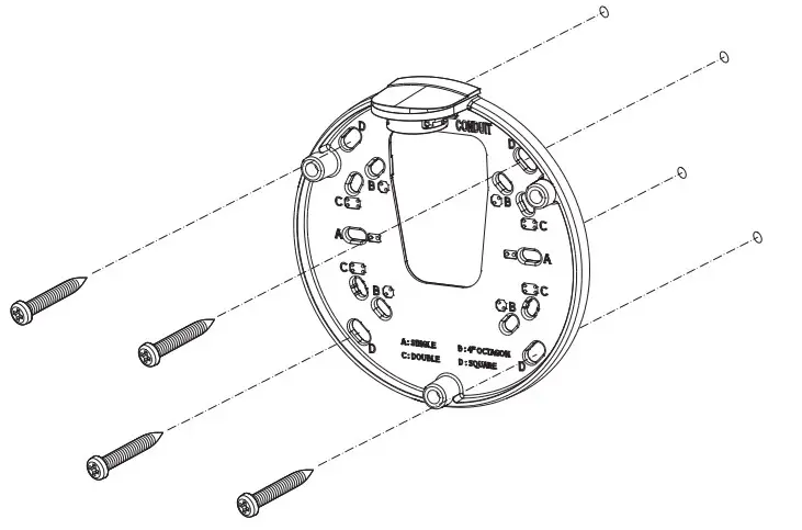
Installation
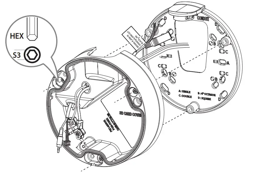
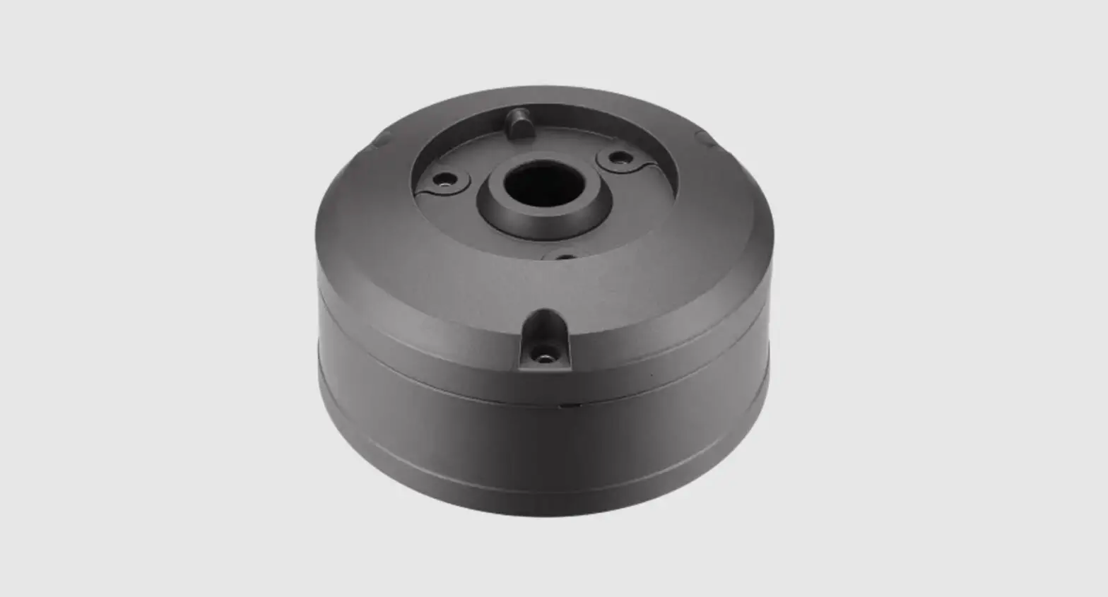
- For installation, separate the BACK BOX.

- Use the installation screws to secure the MOUNT PLATE to the installation surface.
- This product supports installation screw holes of\ SINGLE, 4″ OCTAGON, DOUBLE, and SQUARE types.

- This product supports installation screw holes of\ SINGLE, 4″ OCTAGON, DOUBLE, and SQUARE types.
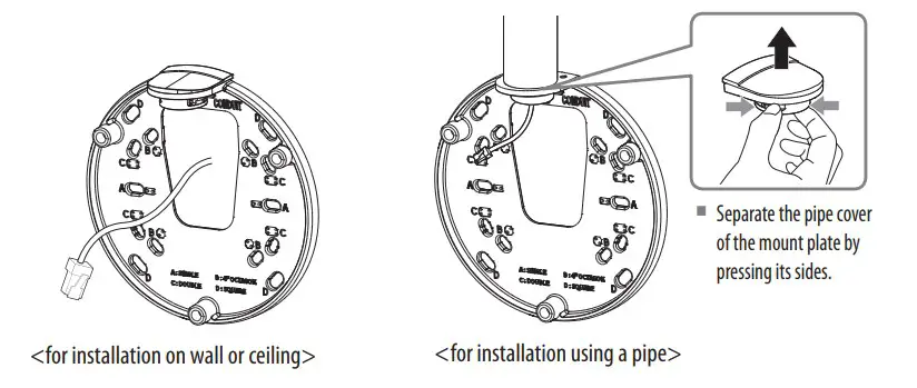
- Install the cable by passing it through the cable hole of the MOUNT PLATE or pipe depending on the installation environment.

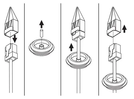
- Pass the network/power cables through the cable bushing.
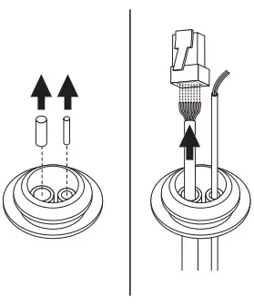
- When installing only the network cable, use the one hole bushing provided as an accessory.

<when installing only network cable>
<When installing network/power cables>
- When installing only the network cable, use the one hole bushing provided as an accessory.
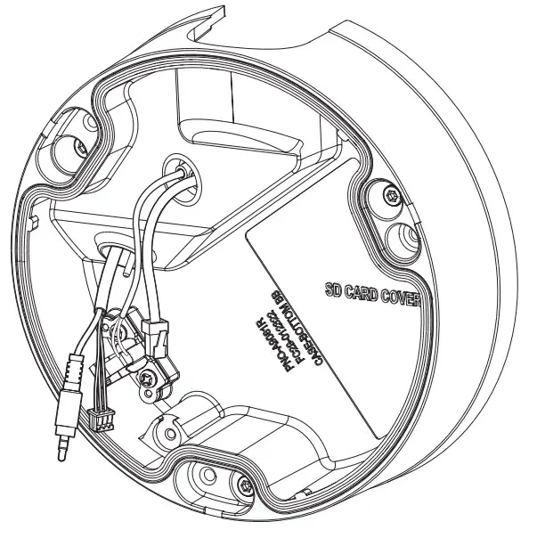
- Insert the network/power cable bushing in the BOTTOM OVER.
- Insert the provided bushing of audio/alarm cable in the BOTTOM COVER.

- Assemble the MOUNT PLATE and BOTTOM COVER.

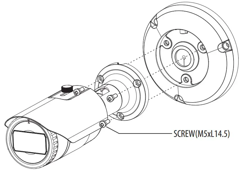
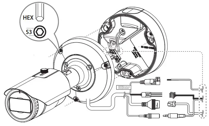
- Use the machine screws to join the camera body to the TOP COVER.

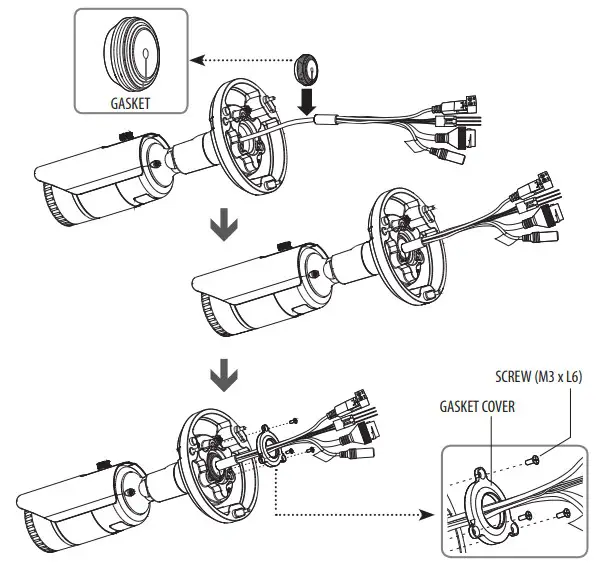
- Use the severed section of the GASKET to insert the bushing into the camera cable.
- Fit the GASKET in the hole of the TOP COVER and assemble the GASKET COVER.

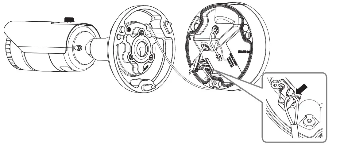
- Hang the safety cable of the TOP COVER on the triangular shaped hook of the BOTTOM COVER.

- Connect the network/power/audio/alarm cables.
- Once these are connected, join the camera body to the BOTTOM COVER.