Kenmore Elite 79041029800 electric range

30″ ELECTRIC SLIDE-IN RANGE INSTALLATION INSTRUCTIONS
INSTALLATiON AND SERVICE MUST BE PERFORMED BY A QUALiFiED iNSTALLER.
IMPORTANT: SAVE FOR LOCAL ELECTRICAL iNSPECTOR’S USE.
READ AND SAVE THESE iNSTRUCTiONS FOR FUTURE REFERENCE.
For existing 29″ (73.7 cm) cutout wide opening, you must call the Service Center for optional thinner side panels. Also you must prepare the countertop edge as shown in the “Countertop Preparation”.
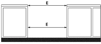
IMPORTANT: Cabinet and countertop width should match the cutout width.
WARNING: Do not install the unit in the cabinet before reading next two pages.
NOTES
- Do not pinch the power supply cord between the range and the wall.
- Do not seal the range to the side cabinets.
- 24″ (61 cm) minimum clearance between the cooktop and the bottom of the cabinet when the bottom of wood or metal cabinet is protected by not less than 1/4″ (0.64 cm) flame retardant millboard covered with not less than No. 28 MSG sheet metal, 0.015″ (0.4 mm) stainless steel, 0.024″ (0.6 mm) aluminum, or 0.020″ (0.5 mm) copper. 30″ (76.2 cm) minimum clearance when the cabinet is unprotected.
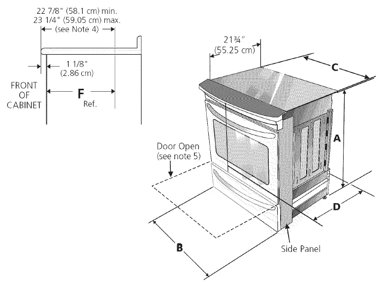
- For cutouts below 22 7/8″(58.1 cm), appliance will slightly show out of the cabinet.
- Allow at least 19 ¼” (48.9 cm) clearance for door depth when it is open.
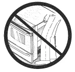
To avoid breakage: Do NOT handle or manipulate the unit by the cooktop glass.
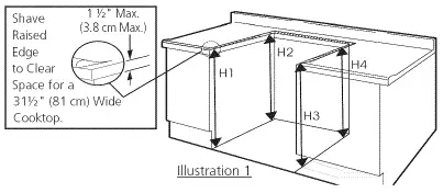
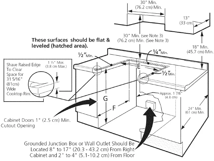
- The counter-top around the cut-out should be flat and leveled (see hatched area on illustration 1).
- Before installing the unit, measure the heights of the two (2) cabinet sides (H1-4), front and back (see illustration 1) from the floor to the top of the counter.
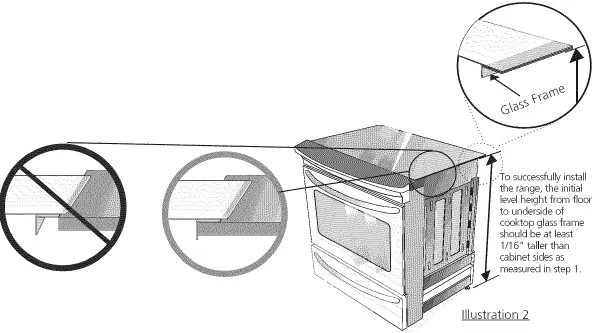
- Level the range using the four (4)leveling legs so that the height from the floor to the underside of the cooktop glass frame is greater than the tallest cabinet measurement by at least 1/1 6″ (see illustration 2).
- Slide the unit into the cabinet. Make sure the center of the unit is aligned with the center of the cabinet cut-out.
- Remove the protective channels on each side of the glass cooktop (if provided).
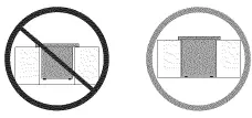
- The metal flange under each side of the cooktop MUST be placed over the cabinet countertop for proper unit support. The glass cooktop should NOT directly touch the countertop (see illustration 2) or could cause glass breakage voiding the warranty. Level the unit if needed.
- After the installation, MAKE sure that the uni is supported by the leveling legs NOT by the cooktop.
Important Notes to the Installer
- Read all instructions contained in these installation instructions before installing range.
- Remove all packing material from the oven and the drawer compartments before connecting the electrical supply to the range.
- Observe all governing codes and ordinances.
- Be sure to leave these instructions with the consumer.
Important Note to the Consumer
Keep these instructions with your owner’s guide for future reference.
IMPORTANT SAFETY INSTRUCTIONS
- Be sure your range is installed and grounded properly by a qualified installer or service technician.
- This range must be electrically grounded in accordance with local codes or, in their absence, with the National Electrical Code ANSI/NFPA No. 70–latest edition.
- The installation of appliances designed for manufactured (mobile) home installation must conform with Manufactured Home Construction and Safety Standard, title 24CFR, part 3280 [Formerly the Federal Standard for Mobile Home Construction and Safety, title 24, HUD (part 280)] or when such standard is not applicable, the Standard for Manufactured Home Installation 1982 (Manufactured Home Sites, Communities and Setups), ANSI Z225.1/NEPA 501Alatest edition, or with local codes.
- Make sure the wall coverings around the range can withstand the heat generated by the range.
- Before installing the range in an area covered with linoleum or any other synthetic floor covering, make sure the floor covering can withstand heat at least 90°F above room temperature without shrinking, warping or discoloring.
WARNING
- All ranges can tip. Injuryto persons could result. Install anti-tip device packed with range.
- To reducethe risk of tipping of the range, the range must be secured by properly installed anti-tip bracket (s) provided with the range. To check if the bracket (s) is installed properly, grasp the top rear edge of the range and carefully tilt it forward to make sure the range is anchored.
- Do not install the range over carpeting unless you place an insulating pad or sheet of I/4″ thick plywood between the range and carpeting.
- Never leave children alone or unattended in the area where an appliance is in use.
- As children grow, teach them the proper, safe use of all appliances. Never leave the oven door open when the range is unattended.
- Stepping, leaning or sitting on the door or drawer of this range can result in serious injuries and can also cause damage to the range.
- Do not store items of interest to children in the cabinets above the range. Children could be seriously burned climbing on the range to reach items.
- To eliminate the risk of burns or fire by reaching over heated surface units, cabinet storage space above the surface unit should be avoided. If cabinet storage is to be provided the risk can be reduce by installing a range hood that project horizontally a minimum of 5 inches beyond the bottom of the cabinet.
- Do not use the oven as a storage space. This creates a potentially hazardous situation.
- Never use your range for warming or heating the room. Prolonged use of the range without adequate ventilation can be dangerous.
- Do not store or use gasoline or other flammable vapors and liquids near this or any other appliance. Explosions or fires could result.
- Reset all controls to the “off” position after using a programmable timing operation.
- FOR MODELS WITH SELF-CLEAN FEATURE: Remove broiler pan, food and other utensils before self-cleaning the oven. Wipe up excess spillage. Follow the pre-cleaning instructions in the Use and Care Guide.
Power Supply Cord Kit
The user is responsible for connecting the power supply cord to the connection block located behind the back panel access cover. This appliance may be connected by means of permanent “hard wiring” ; flexible armored or nonmetallic shielded copper cable (when local code allow it) or by means of a power supply cord kit. See chart (on next page) for the minimum wire size (general UL listing, local code may differ).
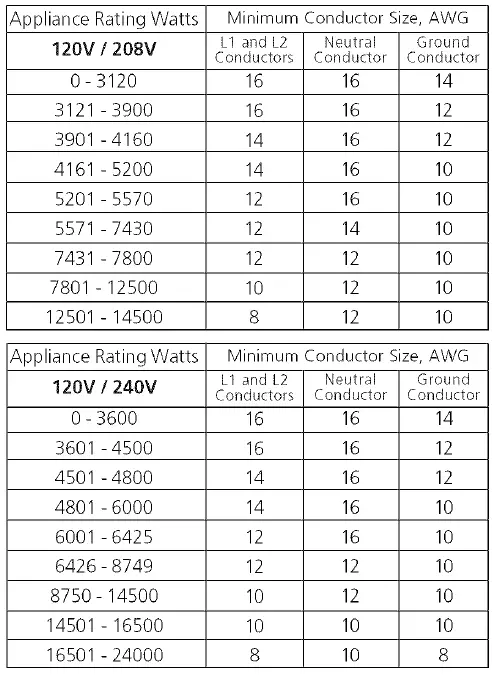
For mobile homes, new installations or recreational vehicles, use only a power supply kit designed for a range at 125V/250V 40A. Cord must have either 3 (when local code permits grounding through neutral) or 4 conductors. The terminal on end of wires must be either closed loop or open spade lug with upturned ends. Cord must have strain-releif clamp. See chart for the minimum wire size (general UL listing, local code may differ).
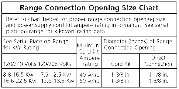
NOTE: Electric Slide-in Range is shipped from factory with I-I/8″ dia. hole as shown on figure 3. If a larger hole is required, punch out the knockout.
WARNING: Risk of fire or electrical shock exists if an incorrect size range cord kit is used, the Installation Instructions are not followed, or the strain relief bracket is discarded.
CAUTION: Do not loosen the nuts which secure the factory-installed range wiring to terminal block while connecting range. Electrical failure or Joss of electrical connection may occur.
The electrical connection to the Range
The appliance is manufactured with the neutral terminal connected to the frame.
WARNING: Electrical Shock Hazard
- Electrical ground is required on this appliance.
- Do not connect to the electrical supply until appliance is permanently grounded.
- Disconnect power to the circuit breaker or fuse box before making the electrical connection.
- This appliance must be connected to a grounded, metallic, permanent wiring system, or a grounding connector should be connected to the grounding terminal or wire lead on the appliance.
- Failure to do any of the above could result in a fire, personal injury or electrical shock.
Three Conductor Wire Connection to Range
If local codes permit connection of the frame grounding conductor to the neutral wire of the copper power supply cord (see Figure 3):
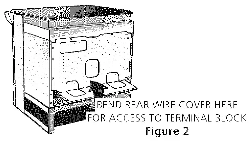
- Remove the 3 screws at the lower end of the rear wire cover, then bend the lower end of the rear wire cover (access cover) upward to expose range terminal connection block (see Figure 2).
- Remove the 3 loose nuts (after you remove the rubber band) on the terminal block using 3/8″ nut driver or socket.
- Connect the neutral of the copper power supply cord to the center silver-colored terminal of the terminal block, and connect the other wires to the outer terminals. Match wires and terminals by color (red wires connected to the right terminal, black wires connected to the left terminal).
- Replace the 3 nuts on the terminal block (see Figure 3).
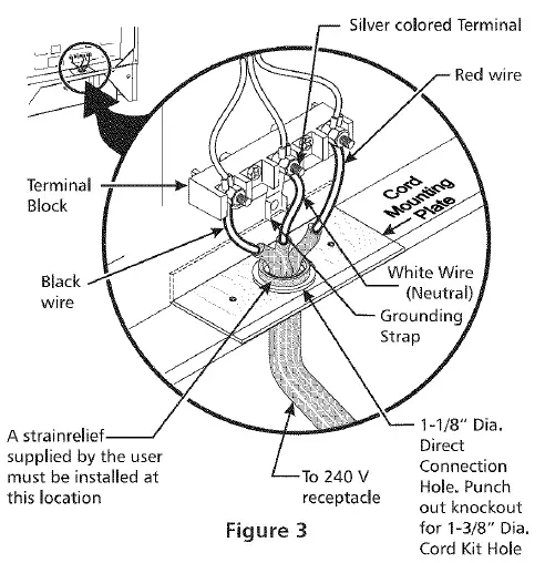
- Lower the terminal cover and replace the 3 screws.
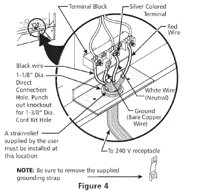
Four Conductor Wire Connection to Range (mobile homes)
- Remove the 3 screws at the lower end of the rear wire cover, then raise the lower end of the rear wire cover (access cover) upward to expose range terminal connection block (see Figure 2).
- Remove the 3 loose nuts (after you remove the rubber band) on the terminal block using a 3/8″ nut driver or socket.
- Remove the ground strap from the terminal block and from the appliance frame.
- Connect the ground wire (green) of the copper power supply cord to the frame of the appliance with the ground screw, using the hole in the frame where the ground strap was removed (see Figure 4).
- Connect the neutral of the copper power supply cord to the center silver-colored terminal of the terminal block, and connect the other wires to the outer terminals. Match wires and terminals by color (red wires connected to the right terminal, black wires connected to the left terminal).
- Replace the 3 nuts on the terminal block (see Figure 4).

- Lower the terminal cover and replace the 3 screws.
Direct Electrical Connection to the Circuit Breaker, Fuse Box or Junction Box
If the appliance is connected directly to the circuit breaker, fuse box or junction box, use flexible, armored or nonmetallic sheathed copper cable (with grounding wire). Supply a U.L listed strain-relief at each end of the cable. At the appliance end, the cable goes through the Direct Connection Hole (see Figure 4) on the Cord Mounting Plate. Wire sizes (copper wire only) and connections must conform to the rating of the appliance.
Where local codes permit connecting the appliance grounding conductor to the neutral (white) wire
- Disconnect the power supply.
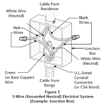
- In the circuit breaker, fuse box or junction box: connect appliance and residence cable wires as shown in figure 5.
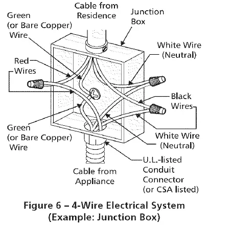
Where local codes DO NOT permit connecting the appliance-grounding conductor to the neutral (white) wire, or if connecting to a 4-wire electrical system (see Figure 6):
- Disconnect the power supply.
- Separate the green (or bare copper) and white appliance cable wires.
- In the circuit breaker, fuse box or junction box: connect appliance and residence cable wires as shown in figure 6.
Cabinet Construction
WARNING: To eliminate the risk of burns or fire by reaching over heated surface units, do not have cabinet storage space above the range. If there is cabinet storage space above range, reduce risk by installing a range hood that projects horizontally a minimum of 5″ (12.7 cm) beyond the bottom of the cabinet.
Countertop Preparation
- The cooktop sides of the range fit over thecutout edge of your countertop.
- If you have a square finish (flat) countertop, no countertop preparation is required. Cooktop sides lay directly on edge of countertop.
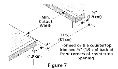
- Formed front-edged countertops must have molded edge shaved flat 3/4″ (1.9 cm) from each front corner of opening (Figure 7).
- Tile countertops may need trim cut back 3/ 4″(1.9 cm)from each front corner and/or rounded edge flattened (Figure 7).
- If the existing cutout width is greater than 30 1/16″ (76,4 cm), reduce the 3A” (1.9 cm) dimension.
- The countertop must be level. Place a level on the countertop, first side to side, then front to back. If the countertop is not level, the range will not be level. The oven must be level for satisfactory baking results.Cooktop sides of range fit over edges of the countertop opening.
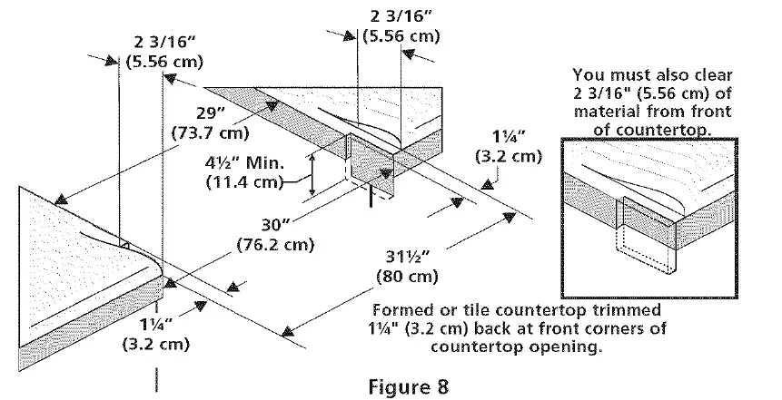
IMPORTANT: For existing cutout width of 29″ (73.7 cm) (Figure 8)
Range Installation
Important Note: Door removal is not a requirement for installation of the range, but is an added convenience.
- Refer to the Use and Care Guide for oven door removal instructions.
Standard Installation
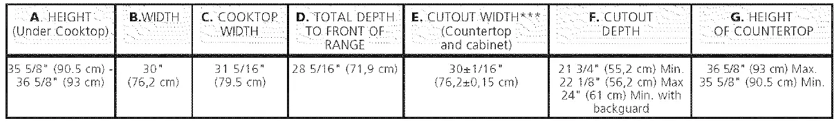
- The range cooktop overlaps the countertop at the I sides and the range rests on the floor. The cooktop is 31 1/2″ (81 cm)wide.
- Install base cabinets 30″ (762 cm) apart. Make sure they are plumb and level before attaching cooktop. Shave raised countertop edge to clear 31 1/2″ (81 cm) wide range top rim.
- lnstall cabinet doors 31 ” (78.7 cm) min. apart so it will not interfere with range door opening.
- Cutout countertop exactly.
- For models equipped with Leveling Device
- Make sure the front leveling legs and the rear leveling device are setup higher than the height of the cabinet.
- CAUTION: Install the anti-tip bracket at this point before placing the range at its final position, Follow the installation instructions or on the anti-tip bracket template supplied with the range.
- To provide an optimum installation, the top surface of the countertop must be level and flat (lie on the same plane) around the 3 sides that are adjacent to range cooktop. Proper adjustments to make the top flat should be made or gaps between the countertop and the range cooktop may occur.
- CAUTION: To reduce the risk of damaging your appliance, do not handle or manipulate it by the ceramic glass. Manipulate with care.
- Position range in front of the cabinet opening.
- Make sure that the cooktop glass which overhangs the countertop clears the countertop. If necessary, raise the unit by lowering the leveling legs.
- Slide the range into the cutout opening and center it before leveling it.
- Level the range (see section 5). The floor wherethe range is to be installed must be level. Follow the instructions under “Leveling the Range- Models Equipped with Leveling Device”.
- Adjust leveling legs so that the underside of the cooktop is sitting on the countertop. Carefully screw in (refer to Leveling the range: Models equipped with Leveling Device”) the back leveling leg until the cooktop glass overhang touches slightly the countertop. Then carefully screw in the front two leveling legs until the cooktop glass overhang touches slightly the countertop.
For models equipped with Leveling Leg only (no leveling device)
- Make sure the four leveling legs (front and rear) are setup higher than the height of the cabinet.
- CAUTION: Install the anti-tip bracket at this point before placing the range at its final position. Follow the installation instructions or on the anti-tip bracket template supplied with the range.
- To provide an optimum installation, the top surface of the countertop must be level and flat (lie on the same plane) around the 3 sides that are adjacent to range cooktop. Proper adjustments to make the top flat should be made or gaps between the countertop and the range cooktop may occur.
- CAUTION: To reduce the risk of damaging your appliance, do not handle or manipulate it by the ceramic glass. Manipulate with care.
- Position range in front of the cabinet opening.
- Make sure that the glass which overhangs the countertop clears the countertop. If necessary, raise the unit by lowering the leveling legs.
- Level the range (see section 5). The floor where the range is to be installed must be level. Follow the instructions under “Leveling the Range-Models Equipped with Leveling Legs”.
- Slide the range into the cutout opening.
IF Accessories Needed
Installation For 29″ Existing Cutout Width Opening
- You must replace the actual side trims by new and smaller side trims. These new side panels can be ordered through a Sears Service Center.
- Follow instructions supplied with your new side trims to replace the actual side trims with the new ones.
- Check if the countertop is prepared for 29″ cutout wide opening.
- Install range as in the “Installation Without Side Panels” section above.
Installation With Backguard
A backguard kit can be ordered through a Sears Service Center.The cutout depth (21 3/4″ (55.2 cm) Min., 22 1/8″ (56.2cm) Max.) needs to be increased to24″ (61 cm) when installing a backyard.
Installation With End Panel
An end panel kit can be ordered through a Sears Service Center.
Installation With Side Panel
A side panels kit can be ordered through a Sears Service Center. Install cabinet doors 31 ” (78.7 cm) rain. apart so as not to interfere with range door opening.
Leveling the Range
Models Equipped with Leveling Device
Level the range after installation in the cutout opening.
- Open the range drawer. The leveling screws control the height of the rear leg.
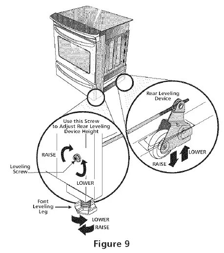
- Adjust the appliance legs as follows until the underside of the cooktop surface is sitting level on the countertop (Figure 9).
- To adjust the front legs, use a wrench on the leg base and turn clockwise to lower or counterclockwise to raise.
- To adjust the rear legs, use a ratchet or a nutdriver and turn the leveling screws counterclockwise to lower or clockwise to raise.
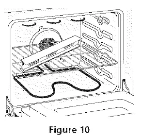
- Check if the range is level by installing an oven rack in the center of the oven and placing a level on the rack (Figure 10).
- Take 2 readings with the level placed diagonally in one direction and then the other. Level the range, if necessary, by adjusting the leveling legs.
- If the range cannot be level, contact a carpenter to correct sagging or sloping floor.
Models Equipped with Leveling Legs
Level the range and set cooktop height before installation in the cut-out opening.
- Install an oven rack in the center of the oven.
- Place a level on the rack (see Figure 10). Take 2 readings with the level placed diagonally in one direction and then the other. Level the range, if necessary, by adjusting the 4 leg levelers with a wrench (see Figure 16).
- Taking care to not damage the countertop, slide range into cutout opening and double check for levelness.
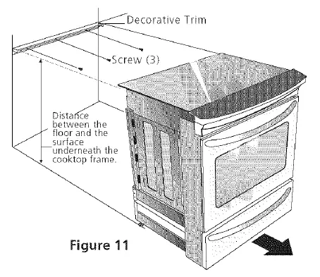
Decorative Rear Trim installation (if required)
- Disconnect the power from the range.
- Make sure the range is leveled.
- Pull range toward you.
- Take the distance between the floor and the surface underneath the cooktop frame.
- Mark that distance on the wall where the decorative trim will be installed.
- Draw a line.
- Place the top of the decorative trim under that line.
- Using the screws provided fix the decorative trim into the wall.
- Slide the range back into position and reconnect the power source (the bottom of the cooktop should be located over the decorative trim).
Check Operation
Refer to the Use and Care Guide packaged with the range for operating instructions and for care and cleaning of your range.
CAUTION: Do not touch the elements. They may be hot enough to cause burns.
Remove all packaging from the oven and the warmer drawer (if equipped) before testing.
Operation of Surface Elements
- Turn on each of the four surface elements and check to see that they heat. Check the surface element indicator light(s), if equipped.
Operation of Oven Elements
The oven is equipped with an electronic oven control. Each of the functions has been factory checked before shipping. However, it is suggested that you verify the operation of the electronic oven controls once more. Refer to the Use & Care Guide for operation. Follow the instructions for the Clock, Timer, Bake, Broil, Convection (some models) and Clean functions.
Bake: After setting the oven to 350°F (177°C) for baking, the lower element in the oven should become red.
Broil: When the oven is set to BROIL, the upper element in the oven should become red.
Clean: When the oven is set for a self-cleaning cycle, the upper element should become red during the preheat portion of the cycle. After reaching the self-cleaning temperature, the lower element will become red.
Convection (some models): When the oven is set to CONV. BAKE/ROAST at 350% (177°C), the convection element cycles on and off and the convection fan turns. The convection fan will stop turning when the oven door is opened during convection baking or roasting.
Warmer Drawer (some models): Set the control knob to HI and check to see the drawer is heating.
When Power Connection is Completed
- Make sure all controls are left in the OFF position.
Model and Serial Number Location
The serial plate is located on the oven front frame behind the oven door (somemodel_ or behind the drawer (some models). When ordering parts for or making inquiries about your range, always be sure to include the model and serial numbers and a lot number or letter from the serial plate on your range.
Before You Call for Service
Read the Before You Call for Service Checklist and operating instructions in your Use & Care Guide. It may save you time and expense. The list includes common occurrences that are not the result of defective workmanship or materials in this appliance.
Refer to your Use & Care Guide for Sears service phone numbers, or call 1-800-4-MY-HOME%.
Anti-Tip Brackets Installation
Instructions- Ceramic Glass Cooktop Only Models Equipped with Leveling Device
WARNING
To reduce the risk of tipping of the range, the range must be secured to the floor by properly installed anti-tip bracket and screws packed with the range. These parts are located in the oven. Failure to install the anti-tip bracket will allow the range to tip over if excessive weight is placed on an open door or if a child climbs upon it. Serious injury might result from spilled hot liquids or from the range itself. Follow the instructions below to install the anti-tip brackets. If range is ever moved to a different location, the anti-tip brackets must also be moved and installed with the range.
Tools Required
- Adjustable Wrench Ratchet
- Drill & I/8″(0,32 cm) bit 5/16″ (0,8 cm) Nutdriver Level
The anti-tip bracket attaches to the floor at the back of the range to prevent range from tipping. When fastening bracket to the floor, be sure that screws do not penetrate electrical wiring or plumbing. The screws provided will work in either wood or concrete.
- Draw a center line (CL) on the floor where the range should be installed. Also draw a line on the floor at the range back position if there is no wall.
- Unfold paper template and place it flat on the floor with the right rear corner positioned exactly on the intersection of the center and back lines you just drew before. (Use the diagram below to locate brackets if template is not available. (Figure 12)
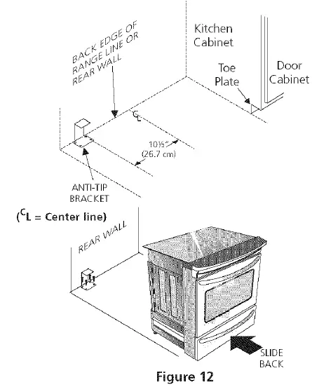
- Mark on the floor the location of the 4 mounting holes shown on the template. For easier installation, 3/ 16″(0,48 cm) diameter pilot holes 1/2″(1,27 cm) deep can be drilled into the floor.
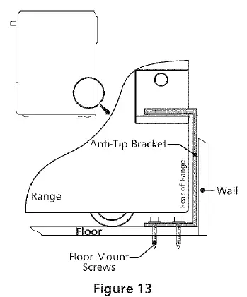
- Remove template and place bracket on floor. Line up holes in bracket with marks on floor and attach with 4 screws provided. Bracket must be secured to solid floor (Figure 13). If attaching to concrete floor, first drill 3/ 16″(0,48 cm) dia. pilot holes using masonry drill bit.
- Be sure the 4 levelling legs are at the highest position they can be.
- Slide range into place making sure structure of the range is trapped by the anti-tip bracket (Figure 12). Lower the range by adjusting the 4 levelling legs until the underside of the cooktop is sitting level on the countertop. Referto “Levelling the Range” section.
- After installation, verify that the anti-tip bracket is engaged by grasping the top rear edge of the range and carefully attempt to tilt it forward to make sure range is properly anchored.
models Equipped with Levellng Legs
Warning: To reduce the risk of tipping of the range, the range must be secured to the floor by properly installed anti-tip brackets and screws packed with the range. These parts are located in a plastic bag in the oven. Failure to install the anti-tip brackets will allow the range to tip over if excessive weight is placed on an open door or if a child climbs upon it. Serious injury might result from spilled hot liquids or from the range itself. Follow the instructions below to install the anti-tip brackets. If range is ever moved to a different location, the anti-tip brackets must also be moved and installed with the range. To check for proper installation, see step 5.
Tools Required
- 5/16″ (0,79 cm) Nutdriver or Flat Head Screwdriver
- Adjustable Wrench
- Electric Drill
- 3/16″(0,5 cm) Diameter Drill Bit
- 3/16″(0,5 cm) Diameter Masonry Drill Bit (if installing in concrete)
Brackets attach to the floor at the back of the range to hold both rear leg levelers. When fastening to the floor, be sure that screws do not penetrate electrical wiring or plumbing. The screws provided will work in either wood or concrete.
- Unfold paper template and place it flat on the floor with the back and side edges positioned exactly where the back and sides of range will be located when installed. (Use the diagram below to locate brackets if template is not available. (Figure 14)
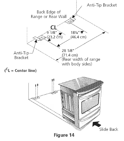
- Mark on the floor the location of the 4 mounting holes shown on the template. For easier installation, 3/16″ (0.5 cm) diameter pilot holes 1/2″ (1.3 cm) deep can be drilled into the floor.
- Remove template and place brackets on floor with turned up flange to the front. Line up holes in brackets with marks on floor and attach with 4 screws provided. Brackets must be secured to solid floor. If attaching to concrete floor, first drill 3/16″ (0.5 cm) dia. pilot holes using a masonry drill bit.
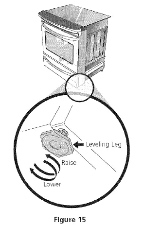
- Level range if necessary, by adjusting 4 leg levelers with wrench (Figure 15). A minimum clearance of 1/ 8″ (0.8 cm) is required between the bottom of the range and the rear leg levelers to allow room for the anti-tip brackets.
- Slide range into place making sure rear legs are trapped by ends of brackets. Range may need to be shifted slightly to one side as it is being pushed back to allow rear legs to slide under brackets. You may also grasp the top rear edge of the range and carefully attempt to tilt it forward to make sure range is properly anchored.
P/N 318201610 (0604) Rev. D


