![]() Engineered in Germany
Engineered in Germany
DOCUMENT REVISION 01
This manual is valid for Australia and New Zealand as of June 1st, 2019 for Q.PEAK DUO-G6, Q.PEAK DUO-G6+, Q.PEAK DUO BLK-G6, and Q.PEAK DUO BLK-G6+ solar modules, and replaces all earlier versions.
This manual is subject to change. The datasheets and customer information valid at the point in time when the relevant module was manufactured apply to the installation, mounting, and maintenance procedures for the respective solar modules, as far as no updated document is provided.
INTRODUCTION
With solar modules from Hanwha Q CELLS Australia Pty Ltd (hereafter referred to as “Q CELLS”), you can directly transform the sun’s limitless energy into environmentally-friendly solar electricity. In order to ensure the maximum performance of your Q CELLS solar modules, please read the following instructions carefully and observe all guidelines. Non-compliance may result in damage and/or physical injury.
This installation and operation manual (hereafter also referred to as the “Manual”) provides instructions for the safe installation and operation of crystalline solar modules.
→ Please read these instructions carefully before proceeding with your installation.
→ Please retain these instructions for the life of the solar modules.
→ Please ensure that this Manual is available to the operator at all times.
→ This Manual should be given to all subsequent owners or users of the solar modules.
→ All supplements received from the manufacturer should be included.
→ Please observe all other applicable documents.
→ If your questions are not satisfactorily answered in the manual, please contact your system supplier. Additional information can be found on our website at www.q-cells.com.
Intended Use
This manual is valid for Australia and New Zealand. These instructions contain information regarding the safe handling and use of quality crystalline solar modules from Q CELLS and their installation, mounting, wiring, maintenance, and disposal.
Symbols and Labels
The following symbols and labels are used throughout the Manual for ease of use.
| SYMBOL | DESCRIPTION |
→ | The procedure with one or more steps. |
• | Lists of items. |
| Ensure that when carrying out a procedure, you check the results of said procedure. | |
| Prohibited. |
Beware of possible danger or damage.
Categories:
- Danger: Risk of fatal injury
- Attention: Risk of serious injury or damage to property
- Note: Risk of damage to the product
Safety Regulations
In particular, the installer, as well as the operator of a module, is responsible for compliance with all applicable statutory requirements and regulations.
→ Unless otherwise specified by any laws or regulations, the following stipulations must be upheld at all times during the installation, operation, and maintenance of the solar modules:
- This manual.
- Other applicable stipulations (such as country-specific regulations for pressure equipment, operational safety, hazardous goods, and environmental protection).
- Regulations and requirements are specific to the system.
- Any applicable laws and requirements, in particular international, country-specific, regional laws and stipulations governing the planning, installation, and operation of solar power systems and work on roofs.
- Any valid international, national, and regional regulations governing work with direct current, especially those applicable to the installation of electrical devices and systems, and regulations issued by the respective energy provider governing the parallel operation of solar power systems.
- Any international, country-specific, and regional accident-prevention regulations.
- Other applicable stipulations provided by the relevant national institutions regarding safety in the installation and operation of electrical items.
Qualified and Skilled Personnel Both, the installer and operator are responsible for ensuring that the installation (including connection to the grid), maintenance, and dismantling are carried out by trained and qualified specialists with approved training certificates (issued by a state or federal organization) for the respective specialist trade. In Australia, electrical work may only be performed by a CEC-accredited licensed electrician complying with valid accident prevention regulations, and regulations of the local energy provider(s). In New Zealand, electrical work may only be performed by a skilled electrician complying with valid accident prevention regulations, and regulations of the local energy provider(s).
Validity
These instructions are only valid for crystalline solar modules from the company Q CELLS as specified in chapter „2.1 Technical Specifications“. Q CELLS assumes no liability for damage resulting from failure to observe these instructions.
→ Please observe the wiring and dimensioning of the system.
→ The installer of the system is responsible for compliance with all necessary safety regulations during set-up and installation.
Q CELLS assumes no liability on the basis of these instructions.
Q CELLS is only liable in the context of contractual agreements or in the context of accepted guarantees. Q CELLS accepts no other responsibility for the functionality and safety of the modules.
→ Please observe the instructions for any other system components that may be part of the complete solar power system.
It may be necessary to carry out a structural analysis for the entire project.
Additional information for the Operator
→Please keep this manual for the entire life of the solar power system.
→ Please contact your system supplier for information concerning the formal requirements for solar power systems.
→ Please be sure to contact the relevant local authorities and energy providers regarding regulations and permit requirements prior to the installation of the solar power system.
Other applicable documents
In addition to this Manual following technical information are relevant:
DOCUMENT TYPE
Product data sheet
Packaging and transport information
PLANNING
TECHNICAL SPECIFICATIONS
| PRODUCT LINE Type | C.PEAK DUO-G6 AK DUO-G6+ Q.ANTUM DUO | Q.PEAK DUO BLK-G6 Q.PEAK DUO BLK-G6+ Q.ANTUM DUO |
| Length | 1740mm | 1740mm |
| Width | 1030mm | 1030mm |
| Frame height | 32mm | 32mm |
| Area | 1.79 m2 | 1.79 rn2 |
| Weight | 19.9 kg | 19.9 kg |
| Max. system voltage Versys | 1000V | 1000 V |
| Max. reverse current | 20A | 20A |
| Permissible temperature range | -40°C to +85°C (-40 °F bis +185 °F) | |
| Junction box protection class | IP67 with bypass diode | |
| Connector protection class | 1P68 | |
| Fire protection class | C / Type 2 | C / Type 2 |
| Max. test load Push/Pull’ | 5,400P8 /4,000 Pa | 5,400Pa/4,000Pa 3,600 Pa / 2.667 Pa |
| Max. design load Push/Pull’ | 3.600 Pa / 2.667Pa | |
| Certificates | VDE Quality Tested; CE-compliant; IEC 61215:2016: IEC 61730:2016; Application Class II; UL 1703 | |
| est and design load in accordance with IEC 61215:2016, depending on mounting options (see the section,,2.3 Mounting Options’) | ||
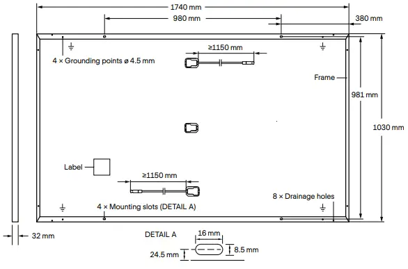
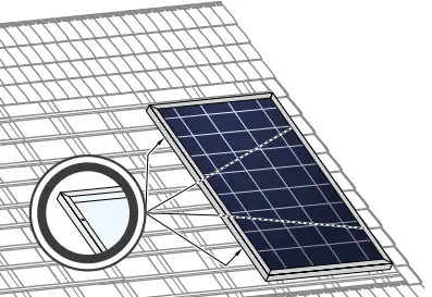
Fig. 1: External dimensions and components for
Q.PEAK DUO-G6, Q.PEAK DUO-G6+,
Q.PEAK DUO BLK-G6 and Q.PEAK DUO BLK-G6+
PLANNING
REQUIREMENTS
Installation Site
Please note the following guidelines that apply to the installation site:
- The modules have been tested according to IEC 61215.
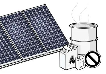
- Solar modules are not explosion-proof and are not suitable for use in explosive environments.
→ Do not operate solar modules near highly flammable gas and vapors (e.g. gas tanks, gas stations).
→ Do not install modules in an enclosed space.
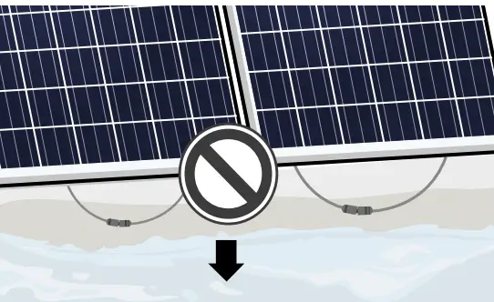
→ Do not install modules in locations where they may be submerged in water (e.g. floodplains).
→ Do not use modules as a substitute for the normal roofing (e.g. modules are not watertight).
→ Do not install modules in close proximity to air conditioning systems.
→ Do not install modules above 4,000 m (13120 ft) altitude above sea level.
→ In locations with increased salt content in the air (e.g. close to the sea) special precautions must be taken (see „Grounding“ and „Maintenance and Cleaning“).
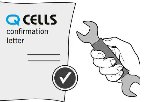
→ Do not bring any chemical substance (e.g. oil, solvent, etc.) into contact with any part of the panel. Only substances, which are released by Q CELLS, are allowed to be used during installation, operation, and maintenance.
→Any installation of modules on surfaces of water is prohibited.
This includes installations on floating as well as pile-based platforms. Q CELLS may extend the coverage of its warranty to such installations, based on a case-by-case assessment of the system design and location. Prior written consent by the warrantor is required in any case.
The solar modules are designed for the following applications:
- Operating temperatures from –40 °C to +85 °C (–40 °F to +185 °F).
- Pull loads up to max. 4,000 Pa and push loads up to max.
5,400 Pa (see chapter „Mounting Options“). - Installation using a mounting structure for solar modules.
Prevention of Shadowing Effects
Optimal solar irradiation leads to maximum energy output:
→ For this reason, install the modules so that they face the sun.
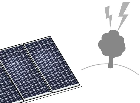
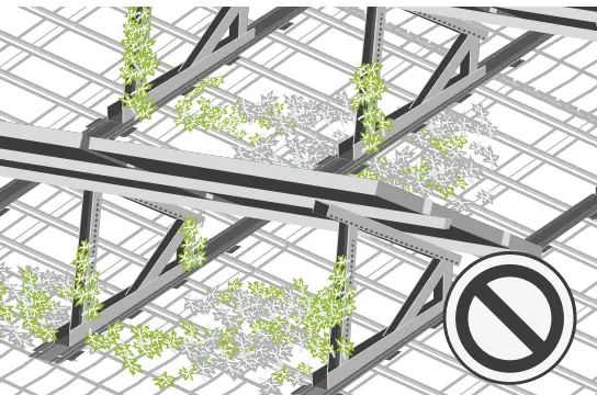
→ Avoid shadowing (due to objects such as buildings, chimneys or trees).
→ Avoid partial shading (for example through overhead lines, dirt, snow).
Mounting Structure Requirements
The Modules shall be installed and operated on mounting structures that comply with any applicable laws and stipulations as well as with the following:
- Conform to the necessary structural requirements.
- Compliant with local snow and wind loads.
- Properly fastened to the ground, the roof, or the façade.
- Forces acting on the module are relayed to the mounting substructure.
- Ensures sufficient rear ventilation of the module.
- Avoid the usage of different metals to prevent contact corrosion.
- Allows for stress-free expansion and contraction due to temperature fluctuations.
→ Ensure that no additional forces are applied through the mounting system into the module except for the wind and snow loads. Additional forces and moments of torque at the mounting positions caused by torsions, displacements or vibrations in the mounting system are not allowed.
→ Ensure that the clamps and the mounting frame are compatible.
Clamp System Requirements
Use customary clamps that satisfy the following requirements:
- Clamp width: ≥ 40 mm.
- Clamp height compliant with a 32 mm frame height.
- Clamp depth: 7-12 mm. (applicable for all CL clamping mounting options at section „2.3 Mounting Options“)
- Clamps are not in contact with the front glass.
- Clamps do not deform the frame.
- Clamps that satisfy the structural requirements of the installation site.
- Long-term stable clamps that securely affix the module to the mounting frame.
Module Orientation Requirements
- Vertical or horizontal installation is permitted.
→ Ensure that rain and melting snow can run off freely. No water accumulation.
→ Ensure that the drainage holes in the frame are not covered.
No sealing.
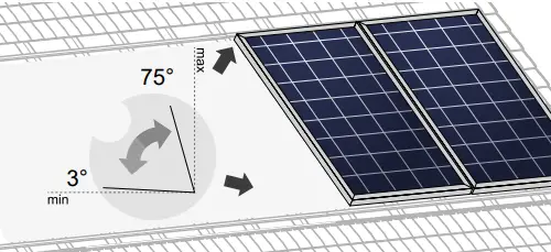
→ Maintain the permissible angle of inclination.
- Minimum angle of inclination: 3°
- Inclination angles above 75° may be limited by local regulations
→≥ 20°: self-cleaning effect
→ Follow the directions for installation angles < 5° („Grounding“, page 18)
PLANNING
MOUNTING OPTIONS
Fig. 2: Installation options for crystalline Q CELLS modules. All dimensions are given in mm. Also, observe the maximum test loads and clamping range as specified on the following page.
The illustrated installation options apply for both horizontal and vertical module orientation.
- Module
- Clamp
- Sub construction
- Mounting profile
| TYPE OF INSTALLATION | MODULE | POINT MOUNTING SYSTEM | LINEAR MOUNTING SYSTEM |
| INSTALLATION WITH CLAMPS | Q.PEAK DUO-G6 Q.PEAK DUO-G6+ Q.PEAK DUO BLK-G6 Q.PEAK DUO BLK-G6+ | 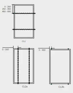 | 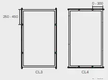 |
| HYBRID CLAMPING | Q.PEAK DUO-G6 Q.PEAK DUO-G6+ Q.PEAK DUO BLK-G6 Q.PEAK DUO BLK-G6+ | 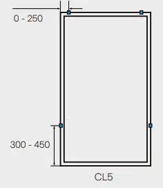 | |
| INSTALLATION ON MOUNTING POINTS | Q.PEAK DUO-G6 Q.PEAK DUO-G6+ Q.PEAK DUO BLK-G6 Q.PEAK DUO BLK-G6+ | 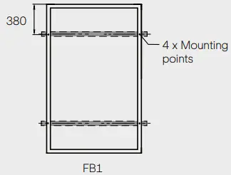 | 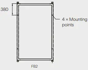 |
| INSTALLATION WITH INSERTION PROFILES | Q.PEAK DUO-G6 Q.PEAK DUO-G6+ Q.PEAK DUO BLK-G6 Q.PEAK DUO BLK-G6+ | NOT PERMITTED |  |
Specifications
| MODULE TYPE
| MOUNTING OPTION | POSITION OF CLAMPS* [MM] | TEST LOAD PUSH/PULL** [PA] | DESIGN LOAD PUSH/PULL** [PA] 3600/2670 | SAFETY FACTOR |
| O.PEAK DUO-G6 (“PEAK DUO-G6+ CD.PEAK DUO BLK-G6 Q.PEAK DUO BLK-G6+ | CL1 / CL3 | 250 – 450 | |||
| FBI / FB2 | 380 | 5400/4000 | |||
| IPI | – | ||||
| I. CL CL2a (with rails) / CL2b (without rails) | 0 – 300 | 1.5 0 – 250 450 – 550 2400/2400 | 1600/1600 | ||
| CL4 | 0 – 300 | ||||
| CL5 | short side: 0 – 250 long side: 300 – 450 | 4000/4000 | 2670/2670 |
→The below mounting options are only possible under certain conditions.
| MODULE TYPE | MOUNTING OPTION | POSITION OF CLAMPS* [MM] | TEST LOAD PUSH/PULL*** [PA] | DESIGN LOAD PUSH/PULL*** [PA] | SAFETY FACTOR |
| Q.PEAK DUO-G6 Q.PEAK DUO-G6+ Q.PEAK DUO BLK-G6 Q.PEAK DUO BLK-G6+ | IP2 | – | 2400/2200 | 1600/1470 | 1.5 |
ATTENTION
→ The loads in the table are related to the mechanical stability of the solar modules. The mechanical stability of the mounting system including clamps has to be evaluated by the system supplier. The Q CELLS listed test load values were determined with the following clamp parameters: clamp width = 40 mm and clamp depth = 10 mm. The system installer is responsible for the determination of location-specific load requirements.
→ Ensure, that the sub-construction does not touch the junction box (even under load). Ensure that the clamps or insertion profiles etc. do not touch the glass (even under load).
→ Ensure, that the connection cables of the junction box do not run between laminate and mounting rails.
→ Ensure, a minimum support depth of 15 mm on the backside of the module for IP1, IP2, CL2b, CL3, CL4, and CL5. Ensure a minimum support depth of 10 mm on the front side of the module for IP1 and IP2.
→ CL1, CL2a, and CL3 with rails: Ensure that the module frame is fixed directly on the rail of the substructure (no spacer allowed between the module and substructure).
→Module bend under loads. Therefore, sharp objects (e.g. screws) must not be mounted near the module backside.
→ Use M8 corrosion-proof screws and washers (diameter ≥ 15.8 mm or ≥ 0.62 in) for FB1 and FB2 mounting.
ELECTRICAL LAYOUT
Module Selection
For detailed key electrical data, please refer to the actual datasheet referring to the relevant Module (available at www.q-cells.com).
→For maximum energy yields, mismatches of specified electric current (IMPP) of more than 5 % should be avoided for all modules connected in series.
Safety Factor
During normal operation, a module may generate a greater current and/or higher voltage than that determined under standardized test conditions. Please use a safety factor of 1.25 for the following:
- Calculating the voltage measurement values (VOC) of components
- Calculating the current measurement values (ISC) of conductors
- Sizing of control systems connected to the outlets of the solar modules
→ Please follow the valid national guidelines for the installation of electrical systems.
→ Please refer to the latest revision of AS/NZS 5033 (including all relevant amendments) and the Clean Energy Council Guidelines (for Australia).
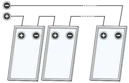
Series Connection
The connection of modules in series is only permitted up to the maximum system voltage as listed in the applicable datasheet of all the relevant modules to be installed.
→ Take into account all possible operating situations and all relevant technical norms and regulations when designing the system. It has to be ensured that the maximum system voltage, including all necessary safety margins, is not exceeded.
→ Take the voltage limit of the inverter into account when determining the maximum number of modules in the string.
Parallel Connection
Modules may be damaged by the occurrence of reverse currents (caused by module defects, ground leaks, or defective insulation).
→ Ensure that the maximum reverse current load capacity indicated in the data sheet is met. In order to limit reverse currents that may occur, we recommend using the following safety options:
- Layout with a limited number of parallel-connected strings :
Please refer to the latest revision of AS/NZS 5033 (including all relevant amendments) for parallel string overcurrent protection requirements. - Layout with string fuses :
Place fuses for each string of modules at the plus and minus ends. Use PV-fuses according to IEC 60269-6. Observe the maximum permitted number of strings as indicated in the specifications provided by the respective string fuse manufacturer and the technical guidelines.
NOTE!
When installing different product versions, the lowest minimum permitted reverse current load capacity applies.
Inverters
Inverters with or without transformers may be used.
INSTALLATION
SAFETY AND TRANSPORT
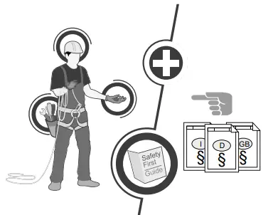
→While working wear clean gloves. | → Do not install damaged modules. → Inform your distributor of any damages immediately. |
 | 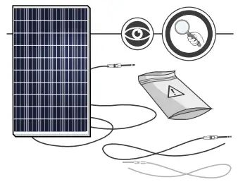 |
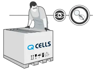
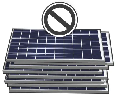
→Contact the transport company regarding any damage to the packaging and follow their instructions. → Follow any instructions on the packaging. | → Do not install modules indoors. → Do not install modules on moving objects. |
 | 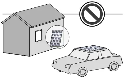 |
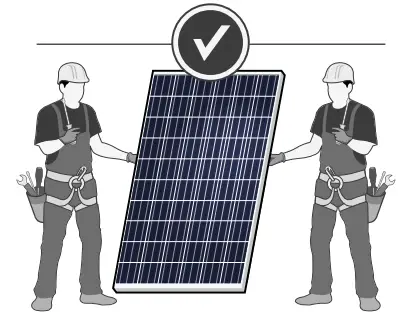
→ Store the modules securely in cool and dry rooms. The packaging is not weatherproof. | → Never lift or move the module with the connection cables or junction box. → Carry modules upright and horizontally as shown. |
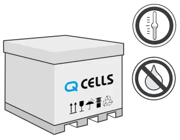 | 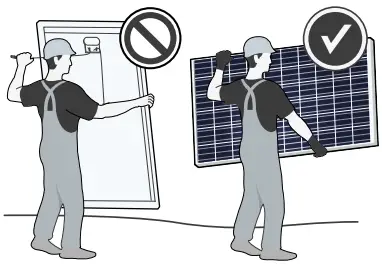 |
→ Never step on modules. → Do not subject modules to any mechanical stress. → Do not allow any objects to fall onto modules | → Do not drop modules. |
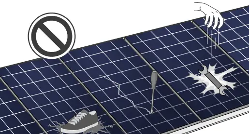 | 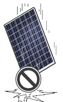 |
| NOTE! Module damage may occur! | NOTE! Module damage may occur! |
 |  |
→ Do not install modules near flammable gas/vapors. → Do not install modules in close proximity to air conditioning systems. | |
 |
PREPARATION OF INSTALLATION
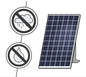
→ Block off the installation zone. → Keep children and unauthorized individuals away from the solar power system. | → Secure modules during installation. → Do not install modules in windy or wet weather. |
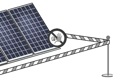 |  |
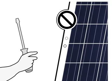
→ Only use dry, insulated tools. | |
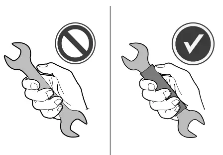 |  |
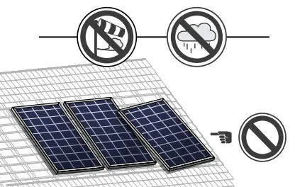
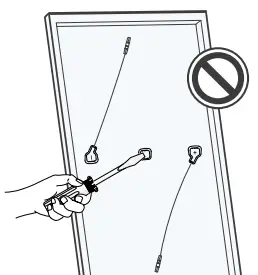
→ Ensure that modules and tools are not subject to moisture or rain at any time during installation. | → Do not modify the module (e.g. do not drill any additional holes). |
 |  |
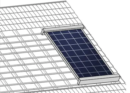
MODULE INSTALLATION
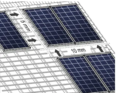
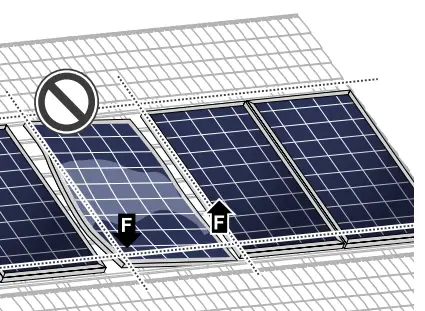
 Option 1: Option 1:→ Fasten the module with 4 clamps in the specified clamping range, see Fig. 2, p. 7. → Tighten clamps according to the manufacturer’s instructions. | → Maintain an interval of at least 10 mm between two modules along the short side and 5 mm along the long side. |
 |  |
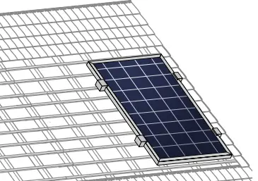
| Option 2: → Install the module at the 4 mounting points, see Fig. 2, p. 7. → Tighten screws according to the manufacturer’s instructions. | → Do not subject modules to a mechanical tension. Max. torsion 10 mm/m. |
 |  |
| Option 3: → Install the module using mounting profiles, see Fig. 2, p. 7. | |
 |
ELECTRICAL CONNECTION
SAFETY
![]() DANGER!
DANGER!
Risk of fatal injury due to electric shock!
When disconnecting an electric circuit carrying direct current, electric arcs can occur that may result in life-threatening injuries.
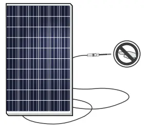
→ Do NOT unplug the cable when under load.
→ Do NOT connect any exposed cable ends.
→ Electrical work may only be performed by qualified and skilled personnel (see page 3).
A solar module generates electrical current and voltage even at a low intensity of illumination. Sparks and electric arcs may result from the separation of a closed circuit. These can result in life-threatening injuries. The danger increases when several
modules are connected in series.
→ Please be aware that the entire open circuit voltage is active even at low levels of solar irradiation.
→ Please follow the valid national regulations and safety guidelines for the installation of electrical devices and systems. Ä
Please make sure to take all necessary safety precautions.
With module or phase voltages of more than 120 V, the safety extra-low voltage range is exceeded.
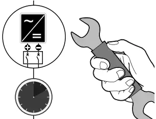
→ Carry out work on the inverter and the wiring with extreme caution.
→ Ensure that the modules are disconnected at the inverter prior to separation.
→ Be sure to observe the time intervals specified by the inverter manufacturer after switching off the inverter.
→ Make sure that the plugs can not be connected unintentionally.
→ Before working on the contacts, check them for safety extra-low voltage.
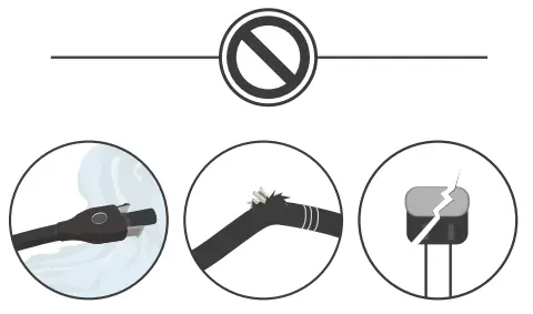
→ Never open the junction box. → Do not remove bypass diodes. | → Never touch live contacts with bare hands. → Cover connectors with suitable protective caps until installation. |
 |  |
→ Only use dry, insulated tools for electrical work. | → Insulate any exposed cable ends. → Only connect cables with plugs. |
| 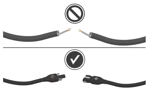 |
ELECTRICAL INSTALLATION SAFETY
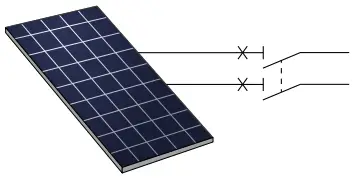
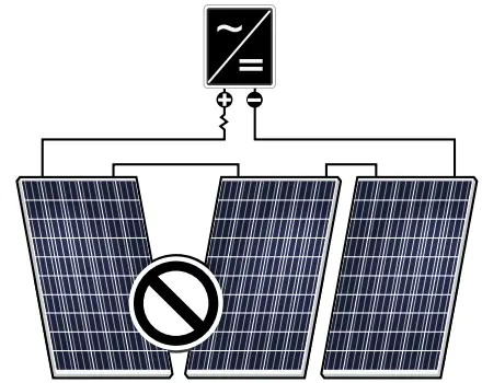
→ Electrical work may only be performed by qualified and skilled personnel (see page 3). → Ensure correct polarity. | → Never plug or unplug the cable when under load. Modules must not carry any current. 1. Switch off the inverter. |
 | 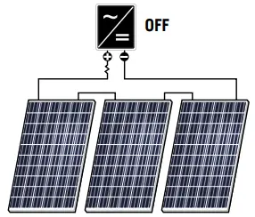 |
→ Be sure to maintain the time intervals as specified by the inverter manufacturer between switching off the inverter and beginning any further work. | 3. Measure shutdown in DC String. (no DC current flow). 4. Disconnect plugs by the use of appropriate and qualified tools of the manufacturer. 5. When connecting the modules proceed in reverse order. |
 |  |
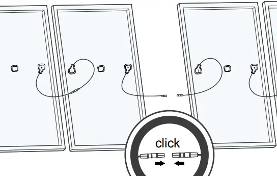
CONNECTION OF MODULES
→ Use the same, inverter-compatible plugs. →Use minimum 4 mm 2 copper wires insulated for a minimum of 90 °C for field connections. | → Ensure that the cabling is not under mechanical stress (Comply with a bending radius of ≥ 60 mm). → Ensure that the cables do not run between the module and mounting rail or structure (danger of pinch). |
 | 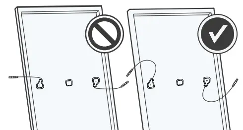 |
→ Ensure that all electrical components are in a proper, dry, and safe condition. | |
 |  |
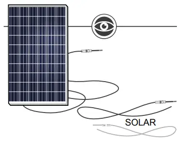
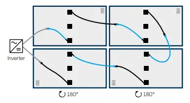
→ Module orientation can clearly be identified from the front side by the serial number and barcode labeled behind the module glass on the side with a negative connection cable. | |
 |  |
AFTER INSTALLATION
→ Ensure that the plug connections are secured away from any water-channeling surface. | |
 |  |
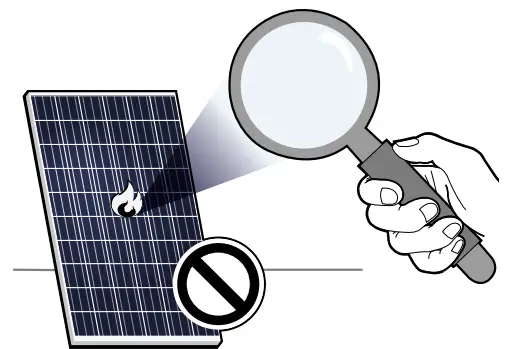
→ Do not use light concentrators (e.g. mirrors or lenses). | |
 |  |
→ Ensure that cables are protected from abrasion, tension, compression, and cutting forces in full accordance with AS / NZS 3000 and all other relevant standards. | → Modules must be cleaned manually and only with sufficient Water. |
 |  |
GROUNDING
Protective Grounding
→ The modules must be grounded in accordance with the local statutory regulations.
Functional grounding
• For installations located in tropic regions (between 23.5° N and 23.5° S) with a module tilt of < 5°, functional grounding at the negative generator connection on the DC side must be implemented.
→ Ensure that the difference of potential between the negative generator connection and the local earth potential (e.g. substructure, PE of the inverter) on each string in operation mode is positive or 0 V.
→Follow the directions of the inverter manufacturer and local statutory regulations.
→ Only use inverters which include licensed grounding kits.
→ Functional grounding has also to be implemented in installation sites with increased salt content in the air. (e.g. close to the sea).
FAULTS AND DEFECTS
![]() DANGER!
DANGER!
Risk of fatal injury due to electric shock!
→ Do not attempt to fix any problems yourself (e.g., glass cracks, damaged cables).
→ Please contact an installer or Q CELLS Technical Customer Service Department.
DISPOSAL
→ Do not disconnect modules by yourself.
→ Please contact an installer or Q CELLS Technical Customer Service Department.
→ Dispose of modules in accordance with the local disposal regulations.
MAINTENANCE AND CLEANING
Q CELLS solar modules are known for long operating life and minimal maintenance effort and expense. Dirt and grime are usually washed away by rain. If the module is fully or partially shaded by dirt or debris (e.g., plants, bird droppings), it needs to be cleaned to prevent a loss of performance.
Maintenance
→ The PV system has to be inspected regularly by certified personnel
→ The time intervals and extent of the inspection can depend
on local circumstances (e.g. salt, ammonia content in the air high humidity, etc.). The customer/operator must inform him about time intervals and extend necessary inspections.
→ Inspections have to be performed especially after extraordinary events (e.g. storm, hail, high snow loads, etc.)
→ During the inspections it has to be checked that the components are secure, undamaged, and clean
Cleaning
![]() WARNING!
WARNING!
Risk of injury due to hot and live modules!
→ Only clean modules that have cooled down.
→ Do not carry or wear any electrically conductive parts.![]() WARNING!
WARNING!
Risk of falling due to unsecured access!
→ Never access the installation area alone or without taking adequate security precautions.
→ Please commission a trade specialist.![]() NOTE!
NOTE!
Module surface damage may occur!
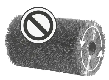
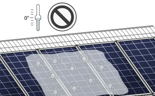
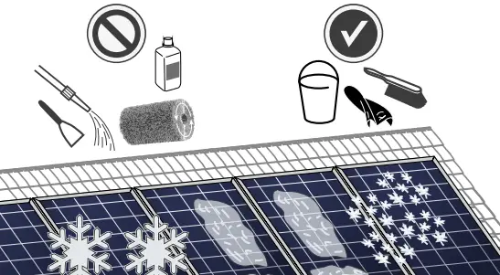
→ Remove snow and ice carefully without force (e.g. with a very soft broom).
→ Do not scratch off the dirt.
→ Rinse dirt (dust, leaves, etc.) off with lukewarm water or use an alcohol-based glass cleaner. Do not use abrasive detergents or surfactants.
→ Use a soft cellulose cloth (kitchen roll) or sponge to carefully wipe off stubborn dirt. Do not use micro fleece wool or cotton cloths.
Isopropyl alcohol (IPA) can be used selectively to remove stubborn dirt and stains within one hour after emergence.
→ Please follow the safety guidelines provided by the IPA manufacturer.
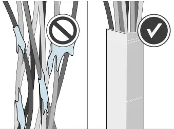
→ Do not let IPA run down between the module and the frame or into the module edges.
→ Do not clean modules with water if there is a risk of frost. | → Do not use surfactants, rotating brushes, scrapers, or any high-pressure water cleaning equipment. | |
 |  |  |
HANWHA Q CELLS
AUSTRALIA PTY LTD
Suite 1, Level 1, 15 Blue Street North Sydney, NSW 2060 Australia
TEL +61 (0)2 9016 – 3033
FAX +61 (0)2 9016 – 3032
EMAIL [email protected]
WEB www.q-cells.com/au
INSTALLATION AND OPERATION MANUAL SOLAR MODULES Q.PEAK DUO-G6.X+ – Q CELLS
Subject to change without notice. © Q CELLS Installation manual solar modules Q.PEAK DUO-G6.X+_2019-06_Rev01_AU


