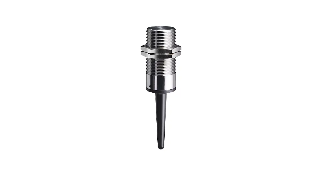
![]() RF RC M30 Wireless Switch
RF RC M30 Wireless Switch
Instruction Manual
RF RC M30 Wireless Switch
![]() // RF RC M30 / RF HS M30 SW868/SW915/SW917/SW922
// RF RC M30 / RF HS M30 SW868/SW915/SW917/SW922
Mounting and wiring instructions / Wireless switch
Use of the mounting and wiring instructions
All actions described in these instructions may only be performed by qualified persons who have been trained and authorised by the operating company.
- Read and understand these mounting and wiring instructions.
- Comply with the valid occupational safety and accident prevention regulations.
- Install and operate the device.
Selection and installation of devices and their integration in control systems demand qualified knowledge of all the relevant laws, as well as the normative requirements of the machine manufacturer. In case of doubt, the German language version of these instructions shall prevail.
Scope of delivery
Device, 1 battery, 1 hexagonal key, mounting and wiring instructions, carton.
Intended use
The device detects the presence or approach of a magnetic actuator and sends a status change notification by remote control.
Power sopply
The device essentially consists of three parts: the power supply with a lithium battery, the wireless part and the sensor. The power supply is provided by a not rechargeable lithium battery CR 2032 with a nominal capacity of 240 mAh. Attention: before commissioning, activate the lithium cell by removing the insulator or inserting the battery. Each switching event activates a wireless transmission. The battery status is transmitted with every signal transmission. The receiver must conform to the sWave® protocol of the steute modules.
Mounting and wiring
Fasten the device according to its design. Install the device according to the mounting and wiring instructions of the receiver. The wireless range depends heavily on the local conditions. Conductive materials may strongly affect the radio signal. This also includes thin foils, e.g. aluminium laminations on insulation materials.
Status signal
A switching signal is transmitted with each switching operation. The switching signal is a telegram. The telegram contains the address of the transmitter, the battery voltage and the current switching status. If a status signal is set, a timer with a defined running time is set. The timer is reset for each switching operation. When the timer expires, a telegram is sent. The telegram contains the same information as the switching signal telegram. By default, the device does not transmit a status signal. Devices with a status signal are available on request. The status signal cannot be set subsequently.
Design of wireless range
The radio signal is attenuated on the way from the transmitter to the receiver. In addition, the radio signal is attenuated/influenced by obstacles. The degree of attenuation depends on the material of the obstacle. The following tables serve as a guide.
Penetration of radio signals:
| Material | Penetration |
| wood, gypsum, glas uncoated | 90…100% |
| brick stone, press boards | 65…95% |
| armoured concrete | 10…90% |
| metal, aluminium lamination, water | 0…10% |
Typical ranges:
| Location | Wireless range (approx.) |
| in free field (SW868/915/917) | 450 m |
| in free field (SW922) | 150 m |
| indoors (SW868/915/917) | 40 m |
| indoors (SW922) | 20 m |
Field strength meter for range test:
| Transmitter | Device | Material No. |
| SW868 | swView 868 MHz | 1190393 |
| SW915 | swView 915 MHz | 1221794 |
| SW917/SW922 | on request | |
Radio operation
The transmission of a switching command from the transmitter to the receiver takes about 80 to 100 ms, based on the sWave® data transmission. The switching signal of a transmitter must not be generated at a shorter distance, otherwise this signal will be overlooked. The receiver must conform to the sWave® protocol of the steute modules. Each switching operation triggers a transmission from the radio unit.
Assignment of locations and radio frequencies:
| Device type | Radio frequency | Location | According to |
| SW868 | 868.3 MHz | EU | 2014/53/EU (RED) |
| SW915 | 915.0 MHz | USA Canada Mexico | FCC IC IFT |
| SW917 | 917.0 MHz | Brazil | ANATEL |
| SW922 | 916.5 MHz | Japan | ARIB STD-T108 |
Mounting notes
Fix the wireless switch to a suitable medium and a through-hole with two nuts. Do not use ferromagnetic material. Install the actuator at a minimum distance of 8 mm to ferromagnetic material. In special cases, perform a functional test. The tightening torques are low, see »Technical data«. The sensor part is sensitive to strikes: do not use the front as an end stop.
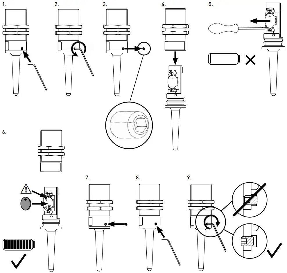
Battery replacement
See section »Battery replacement«.
Safety
Do not use the device in connection with other devices whose direct or indirect purpose is to ensure life or health, or whose operation may pose a threat to humans, animals or material assets.
N.B.
Subject to technical modifications. Reconstruction and alterations to the device are not allowed. It is the responsibility of the manufacturer of a plant or machine to guarantee the correct general function.
Maintenance and cleaning
.steute recommends routine maintenance as follows:
- Remove all dirt particles: Clean enclosure on the outside only.
Clean device in accordance with IP protection class.
Clean with a soft cloth and water or a mild detergent.
Do not clean using compressed air. - Replace damaged parts.
- Test the function.
Disposal
- Observe national, local and legal regulations concerning disposal.
- Recycle each material separately. Dispose of possibly contained batteries correctly.
ESD
Ensure adequate ESD protection for all work that requires opening the unit.
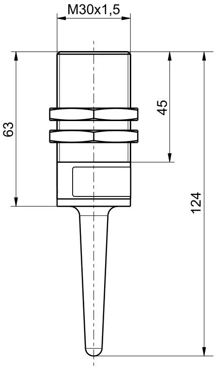
Dimensions
 Battery replacement
![]() Ensure adequate ESD protection!
Ensure adequate ESD protection!
Technical data
| Applied standards | EN 60947-5-1 (RC); EN 60947-5-2 (HS); EN 61000-6-2, EN 61000-6-3; EN 301 489-1, EN 301 489-3; EN 300 220-2 |
| Enclosure/Front surface | PVC-C grey or stainless steel 1.4539 |
| Degree of protection | IP67 to IEC/EN 60529 |
| Ambient temperature | -20°C … +65°C |
| ype of installation | flush, in not ferromagnetic material |
| Tightening torque | RF … M30 Niro: max. 75 Nm; RF … M30 KST: max. 4 Nm |
| Switching system | RC: Reed contact HS: Hall sensor |
| Switching elements | (see receiver product) |
| Utilisation category | (see receiver product) |
| Switching distances | M 100: sn = 15 mm M 30 Niro: sn = 30 mm |
| Hysteresis | <1 mm |
| Actuator | M 100 N Material No. 1042609; M 30 Niro Material No. 1189024 |
| Switching frequency | max. 5 Hz |
| Operation cycles | max. 12,000 telegrams with repetitions/h; SW922: max. 1,440 telegrams/h |
| Actuating time | min. 80 ms |
| Voltage supply | 3.0 V lithium battery CR 2032 (replaceable) |
| Capacity | approx. 230 mAh |
| Standby current | RC: <2 µA (<5 µA activated) HS: <10 µA |
| Battery lifetime | depending on operation cycles (typ. @ 20°C) RC: sensor mainly inactivated every 10 s – 1.1 years every 100 s – 5.0 years every 1,000 s – 7.6 years without – 8.0 years RC: sensor mainly activated every 10 s – 0.9 years every 100 s – 2.7 years every 1,000 s – 3.4 years without – 3.4 years HS: every 10 s – 0.7 years every 100 s – 1.5 years every 1,000 s – 1.7 years without – 1.7 years |
| Protocol | sWave® |
| Frequency | 868.3 MHz (EU) or 915.0 MHz (USA, Canada, Mexico) or 917.0 MHz (Brazil) or 916.5 MHz (Japan) |
| Channel bandwidth | SW868: 480 kHz, SW915, SW917: 550 kHz, SW922: 520 kHz |
| Data rate | 66 kbps |
| Transmission power | SW868, SW915, SW917: <25 mW SW922: <1 mW |
| Wireless range | SW868, SW915, SW917: max. 450 m outdoors, max. 40 m indoors SW922: max. 150 m outdoors, max. 20 m indoors |
| Note | status signal configurable ex works, transmission of battery voltage |
| Wireless approval | EU: RED 2014/53/EU USA: FCC – XK5-RFRXSW915 Canada: IC – 5158A-RFRXSW915 Mexico: IFT – RCPSTRF17-1886 Brazil: Japan: |
Production date 013523 => Monday CW 35 / 2023
| 1 | Monday |
| 2 | Tuesday |
| 3 | Wednesday |
| 4 | Thursday |
| 5 | Friday |
ADDENDUM TO THE MANUAL
MODEL: RF RW SW917
Compliance with Anatel Regulations
This equipment is not entitled to protection against harmful interference and cannot cause interference in duly authorized systems.
This product is approved by ANATEL, in accordance with the procedures regulated by Resolution 242/2000, and meets the technical requirements applied.
For more information, consult ANATEL’s website www.anatel.gov.br
![]() 04172-18-06718
04172-18-06718
EU DECLARATION OF CONFORMITY
As manufacturer, steute Technologies is solely responsible for issuing this Declaration of Conformity.
Type and name of equipment: Wireless magnetic sensor RF RC M30 SW868 …*
* for a detailed product list, see Declaration of Conformity on the internet at www.steute.com
The object(s) of declaration described above is/are in conformity with the following EU harmonisation legislation:
| Relevant EU directives | Applied standards |
| 2014 / 53 / EU Radio Equipment Directive | EN 300 220-2 V3.1.1 EN 301 489-1 V1.9.2 EN IEC 60947-5-1:2017 / AC:2020 EN 61000-6-2:2005 / AC:2005 EN 61000-6-3:2007 / A1:2011 / AC:2012 |
| 2011 / 65 / EU RoHS Directive | EN IEC 63000:2018 |
EU DECLARATION OF CONFORMITY
As manufacturer, steute Technologies is solely responsible for issuing this Declaration of Conformity.
Type and name of equipment: Wireless magnetic sensor RF HS M30 SW868 …*
* for a detailed product list, see Declaration of Conformity on the internet at www.steute.com
The object(s) of declaration described above is/are in conformity with the following EU harmonisation legislation:
| Relevant EU directives | Applied standards |
| 2014 / 53 / EU Radio Equipment Directive | EN 300 220-2 V3.1.1 EN 301 489-1 V1.9.2 EN IEC 60947-5-2:2020 EN 61000-6-2:2005 / AC:2005 EN 61000-6-3:2007 / A1:2011 / AC:2012 |
| 2011 / 65 / EU RoHS Directive | EN IEC 63000:2018 |
Löhne, 20 May, 2022
Place and date of issue Authorized signature,
Marc Stanesby (Managing Director)
Legally binding signature,
Marc Stanesby (Managing Director)
Additional information on mounting and wiring instructions
This mounting and wiring instruction is also available in your national language on request.
steute Technologies GmbH & Co. KG
Brückenstraße 91, 32584 Löhne,Germany,
www.steute.com
135 10 42 / 04.2023 / 144804.Index e / 1000 wd


