![]()
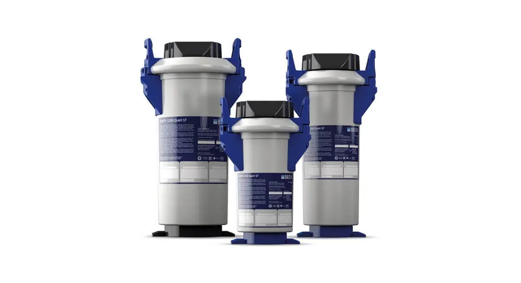
PURITY Quell ST
Water Filter System
 Instruction Manual
PURITY Quell ST Water Filter System
| PURITY | 450 | 600 | 1200 |
| 450 | X | X | |
| 600 | X | X | |
| 1200 | X | X |
The PURITY replacement cartridge may only be used in combination with the pressure vessel that has been specifically designed for its size.
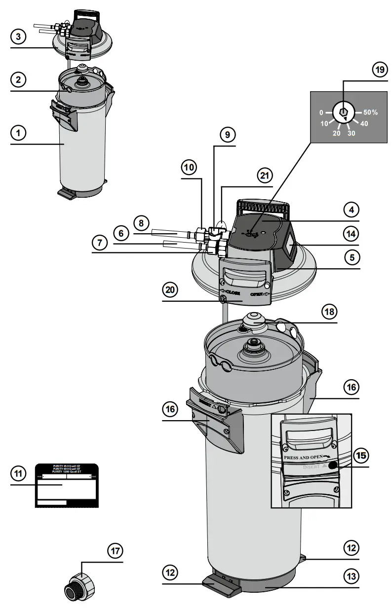
Definition of Terms
- Pressure Vessel
- Filter Cartridge
- Pressure Vessel Lid
- Connector Head (optionally with measuring unit)
- Display Unit (optional)
- Inlet Hose
- Connection Inlet Hose
- Terminal Device Connection
- Flush Valve with Water Outlet
- Connection of Outlet Hose
- Filter Change Sticker
- Kick Loops
- Ejector Base
- Display of the Display Unit (optional)
- Lock
- Mantle Handle
- Reducer 1″– 3/4″
- Transport Protective Cap
- By-pass Screw
- Lid Handle
- Flush Hose
General Information
2.1 Function and Application PURITY Quell ST The BRITA PURITY Quell ST
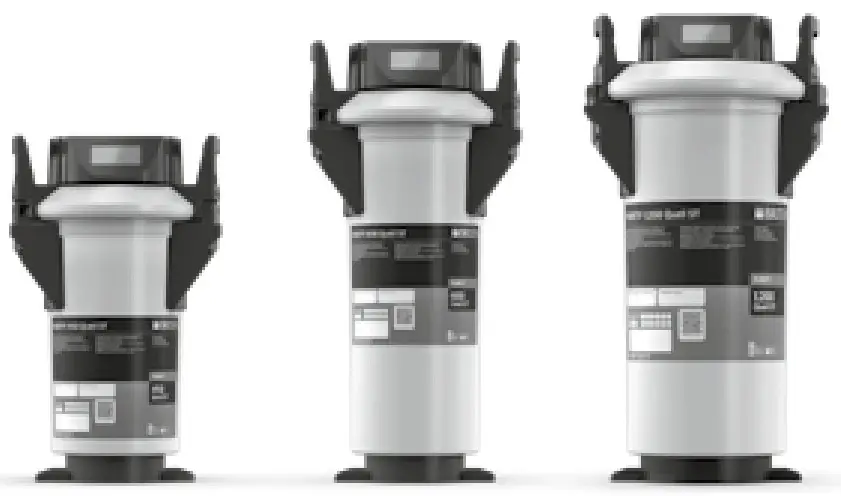
Water Filter System is used for decarbonization of drinking water to prevent limescale deposits in downstream appliances. Depending on the by-pass setting, calcium, magnesium and metal ions can be selectively removed from the drinking water during the flow process. Furthermore, the filter material reduces cloudiness and organic impurities, as well as contents which affect taste and odor (e.g. chlorine residues) in the filtrate and bypass water. By-pass settings on the connector head are used to set the total hardness reduction to the local water hardness or the requirements of the application in order to achieve an optimum water quality. The filter systems are available in 3 different filter system sizes (PURITY 450, PURITY 600 and PURITY 1200) and each in the version without integrated measuring and display electronics or with measuring and display (Advanced Control System, ACS-Technology) electronics. Filter systems with ACS Technology show you the current remaining capacity and bypass setting of your filter cartridge, the set type and size of the filter system and the last replacement date of the filter cartridge. This ensures optimum filter control and water filtrate quality. Further information on the filter system with ACS Technology can be found in Chapter 5.2.
The unique Bintelli Bypass ensures a constant by-pass proportion over the entire usage periods, irrespective of the volumetric flow of the terminal device concerned. The result is a consistently high water quality specifically tailored to the application-specific requirements and the local water conditions.
Typical applications for BRITA PURITY Quell ST water filter systems are coffee and espresso machines, hot and cold drinks vending machines as well as steam ovens (combi ovens) and air humidifiers. The filter system is designed for limited spaces, especially in drinks machines and kitchen installations and can be operated horizontally and vertically. The food quality of BRITA water filter products has been inspected and confirmed by an independent institute.
2.2 Guarantee provisions
The PURITY filter system is subject to the statutory guarantee of 2 years. A guarantee claim may only be asserted if all of the instructions in this manual are followed and observed.
2.3 Storage/Transport
Adhere to the ambient conditions in the Technical Data (Chapter 12) for storage and transport.
The manual should be seen as part of the product and kept for the whole service life of the filter system and passed on to subsequent owners.
2.4 Recycling/Disposal
Disposing of this product and its packaging in the correct manner protects people and the environment.
The battery and display unit must not be burnt and must not be disposed of in domestic waste.
Please ensure that these are disposed of correctly, in accordance with local regulations. See also Chapter 11.
Used filter cartridges can be returned to the BRITA addresses listed (see back of the cover).
Operating and Safety Instructions
3.1 Qualified Personnel
Installation, filter replacement and maintenance of the filter system may be carried out only by specialist staff.
3.2 Correct Use
The product can only operated perfectly and safely if it is installed, used and serviced in the manner described in this manual.
Only solution-specific BRITA filter cartridges may be used for the applications listed.
3.3 Liability Exclusion
Installation must be performed precisely in accordance with the instructions in this manual. BRITA shall not be held liable for any damage, including subsequent damage, arising from the incorrect installation or use of the product.
Specific Safety Information
- Only water of drinking water quality may be used as intake water for the BRITA water filter system. The BRITA water filter system is only suitable for cold water use within the water intake temperature stated in Chapter 12. No microbiologically impaired water or water of unknown quality may be used without appropriate disinfection.
- If there are official instructions to boil tap water, BRITA filtered water must also be boiled. When the requirement to boil water comes to an end, the filter cartridge must be replaced and the connections cleaned.
- It is generally recommended to boil tap water for certain groups of people (e.g. people with weakened immune systems, babies). This also applies to filtered water.
- Note for people with kidney disease or dialysis patients: during the filter process, the potassium content may be increased slightly. If you suffer from kidney disease and/or have to stick to a special potassium diet, we recommend prior agreement with your doctor.
- The water filtrate is classified in Category 2 according to DIN EN 1717.
- BRITA recommends that the filter system not be decommissioned for a long period. If the BRITA filter system is not used for several days (2–3 days), we recommend that the PURITY Quell filter system be flushed with at least x* liters according to the table below. After stagnation periods of over 4 weeks, the filter should be flushed with at least x** Litres (see table below) or else replaced.
Please also note that the maximum usage period of the filter cartridge is 12 months (Chapter 6).Filter system x* flush quantity after 2–3 days stagnation x** flush quantity after 4 weeks stagnation PURITY 450 6 liters 30 liters PURITY 600 12 liters 60 liters PURITY 1200 24 liters 120 liters - The filter system is not resistant to heavily concentrated cleaning agents (e.g. bleach, chlorinated solvents, heavy oxidants) and must not come into contact with them.
- The filter system must not be opened or dismantled during operation. The filter cartridge must not be opened.
- The pressure vessel and the pressure vessel lid of the filter systems have a service life of up to ten years (from the date of installation), provided that they are installed and used correctly and the operating conditions outlined in the Technical Data chapter are adhered to. They must always be replaced after a maximum of ten years. The hoses must be replaced in rotation after a maximum of five years.
- Production date:
| Production code sticker filter cartridge and box, example: 1000231 D 19120020010 | ||
| 1000231 | Article number |  |
| D | Production site (Deutschland/Germany) | |
| 19 | Production year, here: 2019 | |
| 12 | Production week, here: calendar week 12 | |
| 2 | Batch No. of filter medium, here the second batch filled in terms of quantity | |
| 10 | Serial number of the filter cartridge, here the tenth cartridge from the second batch | |
| Production code sticker Display Unit (optional) – Example: 1011208E919319008764 | ||
| 1011208 | BRITA identification number |  |
| E | Supplier ID | |
| 9 | Production year, here: 2019 | |
| 19 | Production week, here: calendar week 19 | |
| 3 | Production day from Monday (1) to Friday (5), here: Wednesday | |
| 19 | Production year, here: 2019 | |
| 8764 | Serial identification number | |
| Production date of pressure vessel and pressure vessel lid, example: 0319 | ||
| 3 | Production month, here: March | 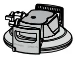 |
| 19 | Production year, here: 2019 | |
3.5 Safety Assembly Instructions
- The terminal device operated with the filter must be free of limescale prior to installation.
- The filter system can also be operated downstream of water softening systems.
- Protect the filter system from sunlight and mechanical damage. Do not assemble near sources of heat and open flames.
- A stop valve must be installed before the filter system intake hose.
- If the water pressure is higher than 6.9 bar or if there are statutory requirements, a pressure reducer must be installed before the filter system.
- A non-return valve according to DIN EN 13959 tested by the DVGW has been factory installed at the water intake of the filter head.
- When choosing the material for parts that come into contact with water after the BRITA filter system, it is important to remember that, due to the process, decarbonized water contains free carbon dioxide. For this reason, only materials that are compatible with free carbon dioxide must be used. We recommend the use of BRITA hoses.
- All parts must be installed in accordance with the country-specific guidelines on the installation of drinking water facilities.
Installation
Caution: Prior to installation, read the Technical Data (Chapter 12) and the Operating and Safety Information (Chapter 3). After the product has been stored and transported at temperatures below 0°C, it must be stored with the original packaging open for at least 24 hours before commissioning.
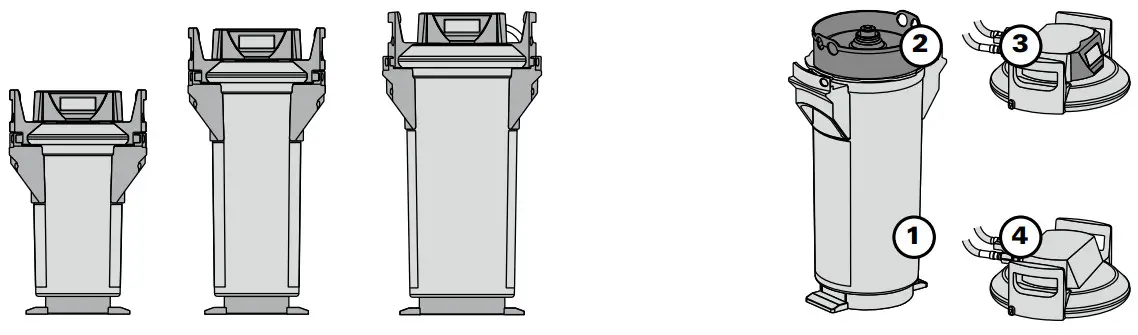
4.1 Delivery Scope
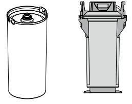
To install a PURITY Quell new filter, you need a pressure vessel 1 , filter cartridge 2 and pressure vessel lid 3 .
Before installing, remove everything included in the delivery from the packaging and check that everything is present:
1 x Pressure Vessel 1
1 x Pressure Vessel Lid 3
1 x Filter Cartridge 2
1 x Manual
1 x Carbonate hardness test or total hardness test
If anything is missing, please contact your local BRITA Office.
4.2 Assembling the Pressure Vessel and the Pressure Vessel Lid
- Stand with both feet on the kick loops 12 .
- Lift the pressure vessel 1 and turn it clockwise until the mantle handles 16 are over the kick loops 12 .
- Remove the transport protective cap 18 from the filter cartridge.
- Check that the O-ring seal of the filter cartridge 2 is correctly seated in the groove and also check for dirt and damage.
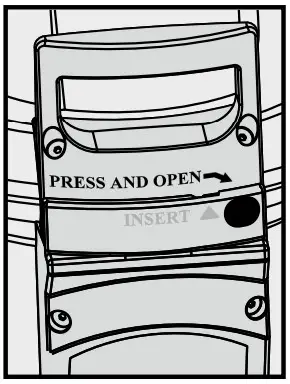
Note: the cartridge seat has been lubricated with food-safe lubricant at the factory. - Stand on the kick loops 12 with both feet and place the pressure vessel lid 3 on the pressure vessel 1 . The position of the arrow marking on the lid handle 20 must match the “INSERT” groove.
- Press the pressure vessel lid 3 down and turn clockwise until the lock 15 engages.
4.3 Assembly of Inlet and Outlet Hoses
Note: The inlet and outlet hoses are not included in the standard scope of delivery. The use of BRITA hose sets is recommended (Chapter 13).
- Fit inlet hose 6 at the inlet of the connector head 4 and outlet hose 10 at the outlet of the connector head 4 .
Note: Inlet “IN” and outlet “OUT” of the connector head 4 are equipped with O-rings as seals, therefore no additional flat seals may be used here. Check that the O- rings are seated correctly.
Caution: The max. tightening torque at the 1″ and 3/4″ connections must not exceed 15 Nm! Only hose connections with flat seals may be used. Hoses with conical screwed connections damage the filter head connections and invalidate any guarantee claims. Only hoses that comply with DVGW-W 543 may be used to connect the device.
Before assembly, note the direction of flow on the upper side of the filter head, “IN” = water inlet, “OUT” = water outlet. Prior to installation, note installation dimensions and operating position (Chapter 12). If no original hoses are used, the 1″–3/4″ 17 adapter supplied must be used to ensure the return valve is sealed correctly (pre-fitted in the water inlet).
Commissioning a New Filter
5.1 By-pass setting for filter systems without and with measuring and display unit
- For PURITY Quell ST filter systems: identify the local carbonate hardness in degrees of German hardness °dH (BRITA nomenclature °KH) using the enclosed carbonate hardness test.
- Check the by-pass setting on the by-pass adjuster 19 .
Note: A 30% by-pass setting has been made in the factory, and might be changed to suit the local carbonate hardness or total hardness and the application (Chapter 7).
5.2 Commissioning the filter systems with measuring and display unit
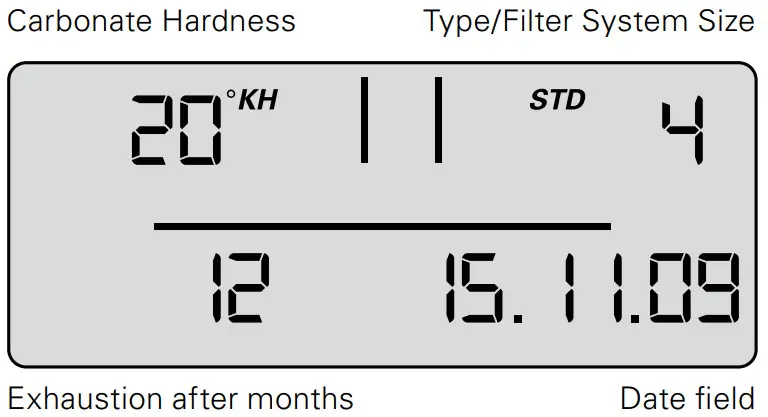
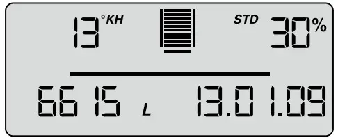
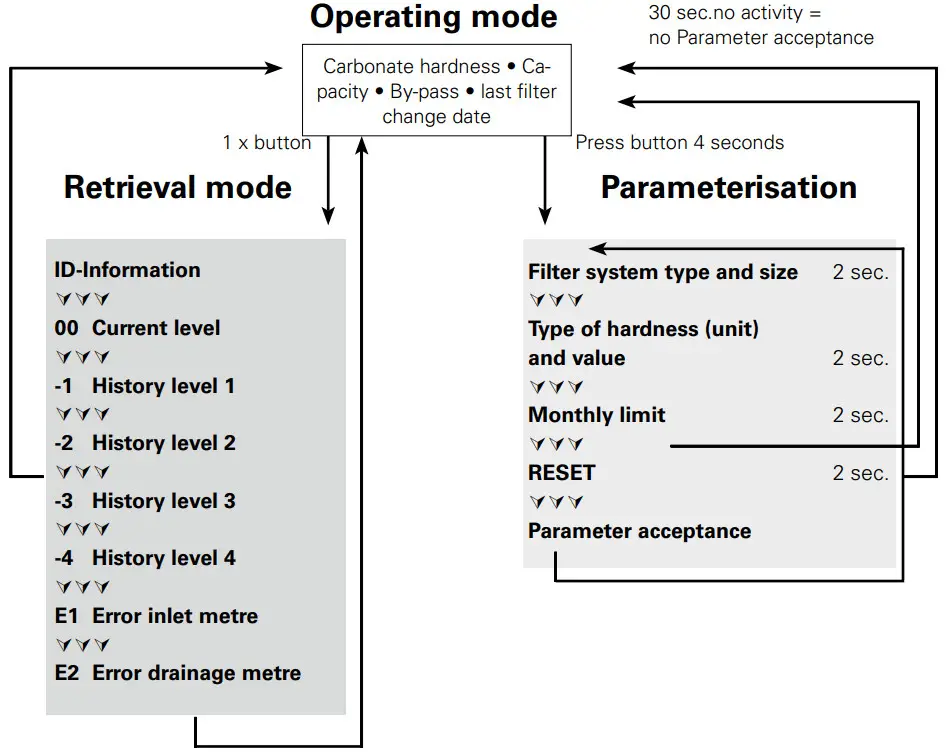
Representation in operating mode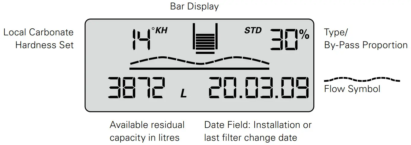
Carbonate hardness
The units of carbonate hardness or total hardness can be set as required to German °dB (= display setting °KH, °DH), English (°e = Clark) (= display setting °EH), French (°f) (= display setting °FH), American (grains per gallon) (= display setting gig) or international hardness values (mg/l CaCO3) (= display setting mg/L).
If the setting for the type of hardness (= unit) is changed while the filter is operating, the values that were set originally are converted automatically.
Bar chart
Representation of the remaining capacity using bar charts. After installation of a new filter system or after a filter change, the symbolized filter cartridge is completely filled with 10 bars.
Bypass proportion in percentage
The by-pass proportion is defined as the proportion of decarbonized water in the total amount of filtrate and is indicated as a percentage.
Flow symbol
When water is removed via the filter system, a graphic wave is shown on the display.
Available remaining capacity of the filter cartridge
The remaining capacity of the filter cartridge is shown in liters or in US gallons, depending on which has been selected.
When water is removed, it counts backwards in 1 liter or 1 US gallon stages. If the cartridge is already exhausted, the capacity is indicated as being negative by flashing.
With a remaining capacity of 20% the last two bars in the bar chart start to flash.
With a remaining capacity of 10% the last bar in the bar chart flashes with the two change arrows.
From a remaining capacity of 0% the negative bars and the change arrows flash alternately with the remaining capacity shown in negative.
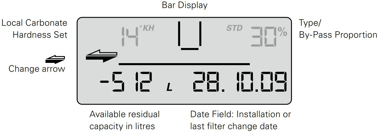
If the monthly limit has been reached up to a month before expiry of the set time limit, it is signaled by the date field flashing.
If the monthly limit is 100% reached, it is signalled by alternate flashing of the date field and the change arrows.
If the remaining capacity and the monthly limit are exceeded, the negative remaining capacity and the date field flash alternately with the change arrows.
Date of the filter commissioning or last filter cartridge change
The date of filter commissioning or last filter cartridge change is indicated as follows:
Example: 28/10/09
| 28 | Day, here the 28th day |
| 10 | Month, here October |
| 9 | Year, here 2009 |
Selecting the units of measurement
You can choose between European, American and international units of measurement on the display.
For European units of measurement: depending on the type of filter system (STD, STM), select the specified unit of measurement for water hardness °KH, °EH, °FH or ° DH. The unit of volume and date format are then automatically displayed in liters and DD/MM/YY respectively.
For American units of measurement, select gig (unit of measurement for water hardness); the unit of volume and the date format are then automatically displayed in US gallons and MM/DD/YY respectively.
For international units of measurement, select mg/L (unit of measurement for water hardness); the unit of volume and the date format are then automatically displayed in liters and DD/MM/YY respectively.
Parameterization
The following parameters have to be entered:
- Filter system type and size
STD 4 = PURITY 450 Quell ST
STD 6 = PURITY 600 Quell ST
STD 12 = PURITY 1200 Quell ST
STM 4 = PURITY 450 Steam
STM 6 = PURITY 600 Steam
STM 12 = PURITY 1200 Steam - Water hardness unit and water hardness value
The following units of hardness may be selected for the various types of filter system:
Unit of carbonate hardness for filter system types STD and STM:
°KH (German unit of hardness)
°EH (English unit of hardness)
°FH (French unit of hardness)
gpg (American unit of hardness)
mg/L (international unit of hardness)
Monthly limit 2–12
Reminder function filter usage period in months
Irrespective of the remaining capacity display function, you can set a monthly limit of 2–12 months to activate a reminder function for filter replacement. If the monthly limit has been reached up to a month before the export of the set time limit, it is signalled by the date field flashing. Factory set to 12 months.
Example: When set to 9 months, the date field starts to flash on the display after 8 months.
Operating the display unit
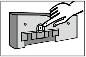
To operate the display unit, it must be removed from the connecting fittings.
Slide the display housing up approx. 10 mm and pull off the display unit.
The display unit is operated using a button on the back of the display unit.
The display unit is supplied in standby mode. To activate the display, press the button on the back once briefly and then reset after inputting the parameters.
Parameter input water hardness and filter system size
At this level, parameters needed for operation are set manually. The type and size of filter system is selected, the unit of hardness is set, the local carbonate hardness or total hardness of the tap water is entered, and the maximum cartridge service life (monthly limit) is activated. After this the parameters must be accepted.
- To activate the display, press the back button once (< 1 second) until the data field appears.

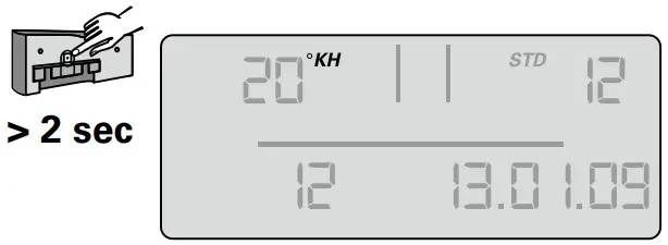
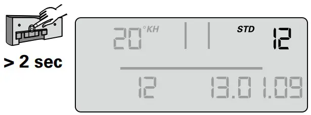
- Press and hold the button (> 4 seconds and < 10 seconds) until the parameter input for the filesystem type and size flashes.

- Press and hold the button (> 2 seconds) until the filter system type (STD, STM) and corresponding value for the filter system size (04, 06, 12) has been reached.

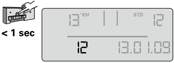
- Press the button once (< 1 second) to access the next parameter input unit of hardness. The unit of hardness flashes.

- Press and hold the button (> 2 seconds) until the desired unit of hardness has been selected.
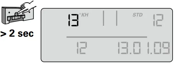
- Press the button once (< 1 second) to access the next parameter input hardness value. The hardness value input flashes.

- Press and hold the button (> 2 seconds) until the value for the water hardness rises and keep it pressed until the desired value has been reached.

- Press the button (< 1 second) to access the next parameter input monthly limit. The monthly limit input flashes.
- Press the button (> 2 seconds) and keep it pressed until the desired value has been reached.


The set parameters can now be accepted.
If you want to accept the parameters, proceed as follows:
- Press the button once (< 1 second) until the message “Reset” appears and flashes.

- Press the button once (> 2 seconds) until the total capacity (at 0% bypass) and the current date appear.


The set parameters have been accepted.
Note: If no input is made within 30 seconds, the display will return to standby or operating mode without accepting amended parameters.
- Insert the display unit from the front at a height of approx. 10 mm and slide down. The loops on the display part must be inserted in the grooves on the measuring head. Continue with Chapter 5.4 Flushing/Draining for Filter Systems with and without Measuring and Display Unit.
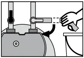
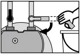
5.3 By-pass setting
Determining the by-pass setting
The by-pass setting is identified according to the application and the carbonate hardness or total hardness identified on the basis of the bypass and capacity table (Chapter 7). The by-pass is then set on the by-pass screw 19 as follows:
Turn the by-pass screw 19 until the desired by-pass (0–50%) agrees with the marking.
Caution: Use Allen key 6mm or 7/32″.
Caution: Never overwind the by-pass screw to avoid any damage.
5.4 Flushing/Bleeding Filter Systems with and without Measuring and Display Unit
Note: A 10 liter bucket is required for flushing/draining.
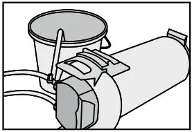
- Position filter system horizontally.
- Completely open flush valve 9 .
- Open the inlet valve 7 at inlet hose 6 while holding the flush hose in the bucket. Flush quantity at least 10 liters with a minimum volumetric flow of 3 l/min (180 l/h).

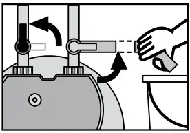
- Close flush valve 9 , put filter system in upright position and empty bucket.
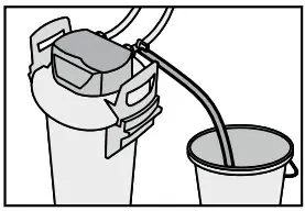
- Carefully open flush valve 9 while holding the flush hose in the bucket. Flush quantity once again at least 10 liters.

- Close flush valve 9 .
- Check system for any leaks.
- Note installation date of the filter system and the next exchange date on the enclosed sticker and attach it to the pressure vessel. Note: There is space for several stickers on the pressure vessel. Apply the new sticker with the installation date at the top position.
Note: Filter systems without measuring and display units are now ready for operation.
5.5 Checking initialization of filter systems with a measuring and display unit
- By-pass setting in percent, remaining capacity in liters, capacity bars and the current date must be shown in the display.
- Note: If these values are not shown in the display, the filter system must be flushed again (Chapter 5.4) until the values are shown in the display. Filter systems with a measuring and display unit are now ready for operation. Cf. Chapters 10.6 to 10.8
Replacing the Filter Cartridge
Caution: The PURITY replacement cartridge may only be used in combination with the pressure vessel that has been specifically designed for its size. See cover.
Caution: During the exchange, carefully examine all dismantled parts! Faulty parts must be exchanged and dirty parts should be cleaned. Read the Operating and Safety Information (Chapter 3) prior to replacement. After the product has been stored and transported at temperatures below 0 °C, it must be stored with the original packaging open for at least 24 hours before commissioning at the ambient temperatures stated in Chapter 12.
Filter systems without a measuring and display unit
The filter cartridge must be replaced after 6–12 months, at the latest 12 months after commissioning, irrespective of the level of exhaustion of the filter system. If the capacity of the filter cartridge has already been exhausted (Chapter 7), it must be exchanged earlier.
Filter systems with a measuring and display unit
The filter cartridge must be replaced no later than 12 months after commissioning, irrespective of the level of exhaustion of the filter system. If the capacity of the filter cartridge has already been exhausted (Chapter 7), it must be replaced earlier.
If the cartridge is already exhausted, the capacity is indicated as being negative by flashing. No bars are shown in the display.
If the monthly limit for the cartridge has been exceeded, this is indicated by the date flashing.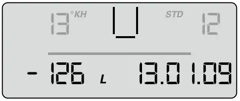
Resetting the display unit
To operate the display unit it has to be removed from the connecting fittings. Slide the display housing up approx. 10 mm and pull off the display unit to the front. The display unit is operated using a button on the back of the display unit.
If this button is pressed (> 10 seconds), the data set on initial installation will be accepted again, and the capacity, by-pass setting and input date are all updated.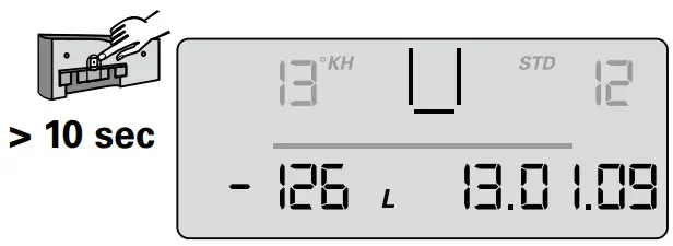
Note: This automatically sets the monthly limit to 12 months.
Note: If no input is made within 30 seconds, the display will return to operating mode without accepting amended parameters.
Insert display unit from front at a height of approx. 10 mm and slide down. The loops on the display part must be inserted in the grooves on the measuring head.
6.1 Removing the Filter Cartridge
- Switch off power supply to the terminal device (remove plug).
- Close inlet valve 7 at inlet hose 6 .
- Place the flushing hose in a bucket and remove pressure from the filter system by opening the flush valve. Catch the escaping water in a bucket.
Note: If the escaping water is more than 1 liter, the inlet valve 7 is not completely closed or is blocked with scale.
- Stand on the kick loops 12 with both feet while opening the pressure vessel lid 3 by pressing the lock 15 and turning it anticlockwise as far as it will go.
- Place the pressure vessel lid 3 vertically on both lid handles 20 .
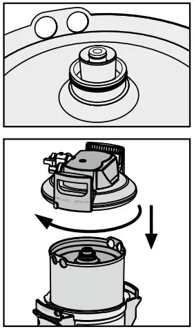
Note: Do not turn the lid horizontally on its head. - Stand on the kick loops 12 with both feet while turning the pressure vessel 1 anticlockwise by the mantle handles 16 as far as it will go.
- Take your feet off the kick loops 12 and press the pressure vessel 1 down with both hands on the mantle handles 16 .
- Remove exhausted filter cartridge 2 from the pressure vessel 1 .
- Place the exhausted filter cartridge 2 in the sink with the connection facing down to drain the remaining water (> 5 min.).
- Lock the exhausted filter cartridge 2 with the transport protective cap 18 of the new filter cartridge and return in the original packaging to the appropriate BRITA address listed on the back of the cover.
6.2 Inserting the Filter Cartridge
- Check the connector seat of the filter cartridge O-ring 2 in the pressure vessel lid 1 for dirt and damage.
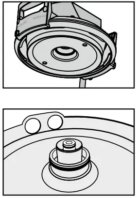
- Check that the O-ring seal of the filter cartridge 2 is correctly seated in the groove and also check for dirt and damage.
Note: The cartridge seat has been lubricated with food-safe lubricant at the factory. - Place the new filter cartridge 2 in the pressure vessel 1 .
- Stand on the kick loops 12 with both feet, lift the pressure vessel 1 turning it clockwise until the mantle handle 16 is over the kick loops 12 .
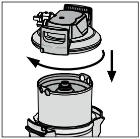
- Stand on the kick loops 12 with both feet and place the pressure vessel lid 3 on the pressure vessel 1 . The positioning of the arrow marking on the lid handle 20 must line up with the “INSERT” groove.
- Press the pressure vessel lid 3 down and turn clockwise until the lock 15 engages.
- Switch on power supply to the terminal device (plug).
- To flush and bleed the new filter cartridge 2 carry out the steps described under 5.3.
Filter Capacity
7.1 Filter Capacity PURITY Quell ST
| Carbonate Hardness in °dH (°KH) | By-pass setting | Filter capacity in Litres | ||
| PURITY 450 | PURITY 600 | PURITY 1200 | ||
| 4 | 50% | 8250 | 14100 | 25800 |
| 5 | 50% | 8250 | 14100 | 25800 |
| 6 | 50% | 8250 | 14100 | 25800 |
| 7 | 50% | 7071 | 12086 | 22114 |
| 8 | 50% | 6188 | 10575 | 19350 |
| 9 | 50% | 5500 | 9400 | 17200 |
| 10 | 40% | 4217 | 7207 | 13187 |
| 11 | 40% | 3833 | 6552 | 11988 |
| 12 | 30% | 3077 | 5260 | 9624 |
| 13 | 30% | 2841 | 4855 | 8884 |
| 14 | 30% | 2638 | 4508 | 8249 |
| 15 | 30% | 2462 | 4208 | 7699 |
| 16 | 30% | 2308 | 3945 | 7218 |
| 17 | 30% | 2172 | 3713 | 6793 |
| 18 | 30% | 2052 | 3506 | 6416 |
| 19 | 30% | 1944 | 3322 | 6078 |
| 20 | 20% | 1650 | 2820 | 5160 |
| 21 | 20% | 1571 | 2686 | 4914 |
| 22 | 20% | 1500 | 2564 | 4691 |
| 23 | 20% | 1435 | 2452 | 4487 |
| 24 | 20% | 1375 | 2350 | 4300 |
| 25 | 20% | 1320 | 2256 | 4128 |
| 28 | 20% | 1179 | 2014 | 3686 |
| 31 | 20% | 1065 | 1819 | 3329 |
| 35 | 20% | 943 | 1611 | 2949 |
By-pass and capacity table for combo ovens and conventional ovens Depending on machine type, select by-pass setting 10% to achieve optimally treated water for the combo oven/conventional oven. We will be happy to make specific recommendations.
| Carbonate Hardness in °dH (°KH) | By-pass setting | Filter capacity in liters | ||
| PURITY 450 | PURITY 600 | PURITY 1200 | ||
| 4 | 10% | 4991 | 8530 | 15607 |
| 5 | 10% | 4991 | 8530 | 15607 |
| 6 | 10% | 4991 | 8530 | 15607 |
| 7 | 10% | 4278 | 7311 | 13378 |
| 8 | 10% | 3743 | 6397 | 11706 |
| 9 | 10% | 3327 | 5686 | 10405 |
| 10 | 10% | 2995 | 5118 | 9364 |
| 11 | 10% | 2722 | 4652 | 8513 |
| 12 | 10% | 2496 | 4265 | 7804 |
| 13 | 10% | 2304 | 3937 | 7203 |
| 14 | 10% | 2139 | 3655 | 6689 |
| 15 | 10% | 1996 | 3412 | 6243 |
| 16 | 10% | 1872 | 3199 | 5853 |
| 17 | 10% | 1762 | 3010 | 5508 |
| 18 | 10% | 1664 | 2843 | 5202 |
| 19 | 10% | 1576 | 2694 | 4929 |
| 20 | 10% | 1497 | 2559 | 4682 |
| 21 | 10% | 1426 | 2437 | 4459 |
| 22 | 10% | 1361 | 2326 | 4257 |
| 23 | 10% | 1302 | 2225 | 4071 |
| 24 | 10% | 1248 | 2132 | 3902 |
| 25 | 10% | 1198 | 2047 | 3746 |
| 28 | 10% | 1070 | 1828 | 3344 |
| 31 | 10% | 966 | 1651 | 3021 |
| 35 | 10% | 856 | 1462 | 2676 |
Note: The capacity limits refer to average utilization of the terminal equipment, do not contain any filter flushing and cleaning cycles and depend on local water quality, flow, mains pressure and flow continuity.
Repair
Regularly check the filter system for leaks. Regularly check the hoses for kinks. Bent hoses must be replaced.
The complete filter system must be replaced in rotation after a maximum of ten years.
The hoses must be replaced in rotation after a maximum of five years.
Caution: Prior to changing, read the Technical Data (Chapter 12) and the Operating and Safety Information (Chapter 3).
Regularly clean the outside of the filter system with a soft, damp cloth.
Caution: Do not use any substances incompatible with the material (Chapter 3.4) or abrasive cleaning materials.
Query Mode
The following data can be queried in the query mode:
Production data
- Briefly press button 1 x (< 1 second), the following message appears.

Production year: Example 08 = 2008
Device number: consecutive
Battery useful life: Example 31/12/19 = The battery in the display unit will be exhausted on 31/12/19 and the complete filter system has reached its max. usage period.
Total volume meter
- Briefly press button 2 x (< 1 second), the following message appears. 00 level current data (today)
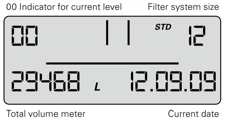
The total volume meter is managed at this level; it counts up from 0 irrespective of the cartridge change.
Memory Call-Up
In the Memory Call-Up mode, the data of the last 4 filter cartridges used can be called up.
- Briefly press button 3 x (<1 second) until the following message appears.
-1, -2, -3, -4 level – data of the cartridges used before the current one.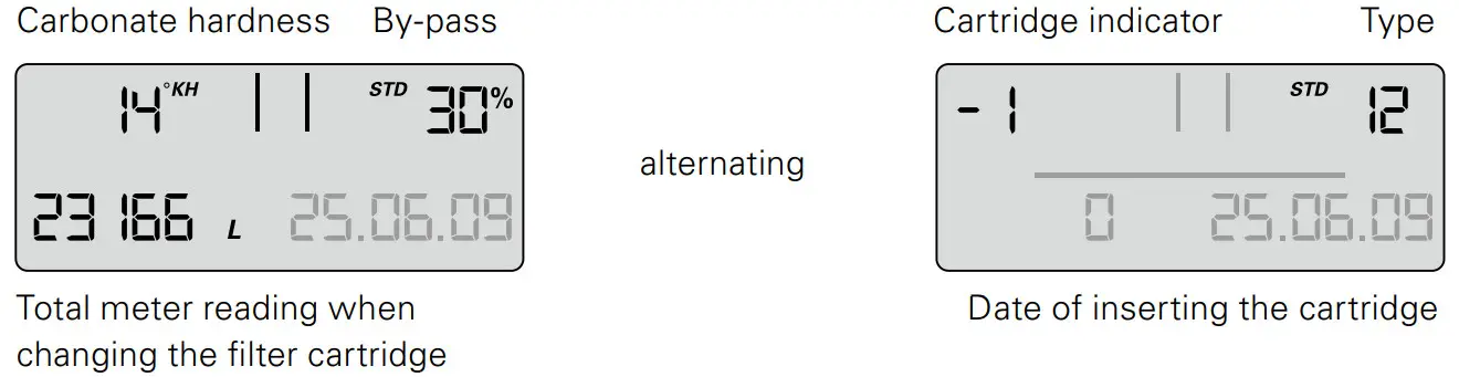
At the top left, the indicator for the filter cartridge (-1 for previous filter cartridge) is displayed alternately with the carbonate hardness set and the hardness unit. At the top right, the filter system size is displayed alternately with the by-pass setting (display 1 s indicator, 1 s carbonate hardness), at the bottom left, the meter reading when changing the cartridge (-1) and at the bottom right, the installation date of the cartridge.
Meaning: the filter cartridge most recently used was a PURITY 1200 cartridge, the filter cartridge was inserted on 25/06/09 and operated up to a meter reading of 23166 liters.
The carbonate hardness set was 14°KH and the by-pass measured was 30%.
The same applies to the cartridge(-2), preceding filter cartridge and the other preceding filter cartridges -3, -4.
Error Messages
Error level E1 indicates whether an error has occurred in blend detection.
E1 is activated as soon as the current bypass is not correctly identified.
The word Start is then displayed together with the date of occurrence.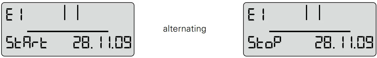
As soon as the current bypass setting is identified correctly again, the error has ended and the Stop date is added. At error level 01 the Stop and Start display alternates every second.
Error level E2 indicates whether and from when until when an error has occurred at the outlet water meter. Display is similar to level E1.
Program Overview
20 sec. no activity
Troubleshooting
10.1 No water flow
Cause: Water intake closed.
Troubleshooting: Open water intake on the upstream stop valve or inlet valve 7 on inlet hose 6 .
Caution: Installation and maintenance of the filter system may be carried out only by specialist staff.
10.2 No or low water flow in spite of open water intake
| Cause: | Mains pressure too low. |
| Troubleshooting: | Check mains pressure. If the fault continues in spite of adequate mains pressure, check the filter system and filter cartridge and change if necessary. Caution: Prior to changing, read the Technical Data (Chapter 12) and the Operating and Safety Information (Chapter 3). |
10.3 Leak at Screwed Connections
Cause: Screwed connections not fitted correctly.
Troubleshooting: Check mains pressure. Check all screwed connections and mount according to Chapter 4.
If the fault continues, exchange filter system.
! Caution: Prior to changing, read the Technical Data (Chapter 12) and the Operating and Safety Information (Chapter 3).
10.4 Leak after Filter Replacement
Cause: O-ring at the filter cartridge is not seated correctly.
Troubleshooting: Check correct seat of the O-ring (Chapter 6.2).
! Caution: Prior to dismantling read the data (Chapter 12) and the Operating and Safety Information (Chapter 3).
10.5 No Display Function
Cause: Battery drained.
Troubleshooting: Replace display unit (Order number see Chapter 13).
Note: When replacing the display unit, follow the enclosed manual.
10.6 Data on Display Flashing
Cause: Monthly limit expired or the remaining capacity of the filter cartridge is exhausted (Chapter 5.2).
Troubleshooting: Replace filter cartridge (Chapter 6).
10.7 Bypass setting in the display does not agree with the setting of the bypass screw (cf. 10.8/10.9)
Cause: Filter was not commissioned correctly.
Troubleshooting: Flush filter again (Chapter 5.4). Check data in the display after flushing (Chapter 5.5).
10.8 Bypass setting in the display does not agree with the setting of the bypass screw (cf. 10.7/10.8)
Cause: Valve strip of the by-pass setting not set correctly.
Troubleshooting: Flush filter system again and readjust bypass screw (Chapter 5.3)
Battery
The installed battery is designed for a service life of approx. 10 years. The battery and display unit must not be burnt and must not be disposed of in domestic waste.
To remove the battery, please proceed as follows:
- Remove the screw on the back of the display unit and open and remove the back of the housing.
- Disconnect the soldered contacts on the battery with side cutters and remove the battery from the bracket.
- Replace the back of the housing on the display unit and tighten the screw.
Dispose of the battery and display unit following the local environmental guidelines for battery disposal.
Technical Data
PURITY Quell ST filter system
| PURITY 450 Quell ST | PURITY 600 Quell ST | PURITY 1200 Quell ST | |||||
| MDU* | without MDU* | MDU* | without MDU* | MDU* | without MDU* | ||
| Operating pressure | 2 bar — max. 6.9 bar | ||||||
| Operating/water temperature | 4°C to 30°C | ||||||
| Ambient tempera- true during | operation | 10°C to 40°C | |||||
| storage | —20°C to 50°C | ||||||
| Flow rate with 1 bar pressure loss | 300 I/h | I 350 I/h | 300 I/h | I 350 I/h | 300 I/h | I 350 I/h | |
| Empty filter cartridge volume | 3.9 I | 5.8 I | 10 9 I | ||||
| Weight (dry/wet) | 10 kg/12 kg | 12 kg/15 kg | 18 kg/24 kg | ||||
| Dimensions | 249 mm/222 mm/408 mm | 249 mm/222 mm/520 mm | 288 mm/255 mm/550 mm | ||||
| Operating position | Vertically or horizontally | ||||||
| Inlet connection | G 1″ | ||||||
| Outlet connection | G 3/4″ | ||||||
* Measuring and Display Unit![]() System Tested and Certified by NSF International against NSF/ANSI Standard 42 for the reduction of Chlorine taste and odor and against CSA B483.1.
System Tested and Certified by NSF International against NSF/ANSI Standard 42 for the reduction of Chlorine taste and odor and against CSA B483.1.
Order Numbers
! Caution: The PURITY replacement cartridge may only be used in combination with the pressure vessel that has been specifically designed for its size. See cover.
PURITY Quell ST
| Article number | I | Item | ||
| PURITY 450 Quell ST | ||||
| PURITY 450 Quell ST (Complete System with Filter Cartridge) with Measuring and Display unit | 1009227 | 1 | + 2 | + 3 |
| PURITY 450 Quell ST (Complete System with Filter Cartridge) | 1009228 | 1 | + 2 | + 4 |
| Filter cartridge | 273000 | 2 | ||
| PURITY 600 Quell ST | ||||
| PURITY 600 Quell ST (Complete System with Filter Cartridge) with Measuring and Display unit | 1009229 | 1 | + 2 | + 3 |
| PURITY 600 Quell ST (Complete System with Filter Cartridge) | 1009230 | 1 | + 2 | + 4 |
| Filter cartridge | 273200 | 2 | ||
| PURITY 1200 Quell ST | ||||
| PURITY 1200 Quell ST (Complete System with Filter Cartridge) with Measuring and Display unit | 1009231 | 1 | + 2 | + 3 |
| PURITY 1200 Quell ST (Complete System with Filter Cartridge) | 1009232 | 1 | + 2 | + 4 |
| Filter cartridge | 273400 | 2 | ||
BRITA Wasser-Filter-System AG
Cassatt 6
6025 Neudorf/LU
Switzerland
Tel. +41 41 932 42 30
[email protected]
www.brita.ch 
BRITA Professional Filter Service App
The new Filter Service App is your ideal assistant. This unique, comprehensive tool helps determine the right type and size of filter for your precise needs. It provides detailed installation guidance for service engineers, calculates when cartridges will need replacing – andhas a wealth of other, innovative capabilities.
Download it for free on
![]() or visit
or visit
https://professional.brita.net/app
![]() Information in the manual are subject to change.
Information in the manual are subject to change.
BRITA is a registerd trademark of BRITA SE, Germany.
References
 sec.no is parked
 BRITA waterfilter | BRITA®
-
BRITA Wasserfilter | BRITA®
-
BRITA water filter | BRITA®
-
BRITA water filter and BRITA water filter systems | BRITA®
-
BRITA filtro de agua | BRITA®
-
BRITA filtre à eau | BRITA®
-
BRITA filtri per l'acqua | BRITA®
-
BRITA water filter | BRITA®
-
BRITA waterfilter | BRITA®
-
BRITA filtr do wody I BRITA®
-
BRITA Professional Filter Service


