![]()
![]()
INFORMATION
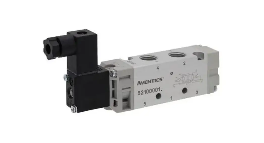
High-Speed Pilot Operated Solenoid Valve
High Speed
ON 2.5 ms OFF 3 ms
| Large flow rate | Enclosure |
| 330 ∗1 L/min (ANR) | IP67 |
| Power saving | Select from 3*2 or 5 port. |
| 1.5 W (With power-saving circuit) |
Compact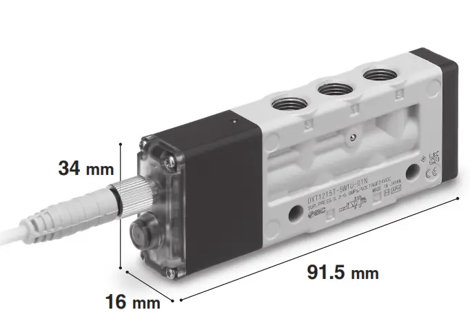
- When the inlet side is 0.6 MPa, and the differential pressure is 0.1 MPa
- 3-port type: Made to order (-X1)
Applications
Can be used for the air blow and high-speed operation of actuators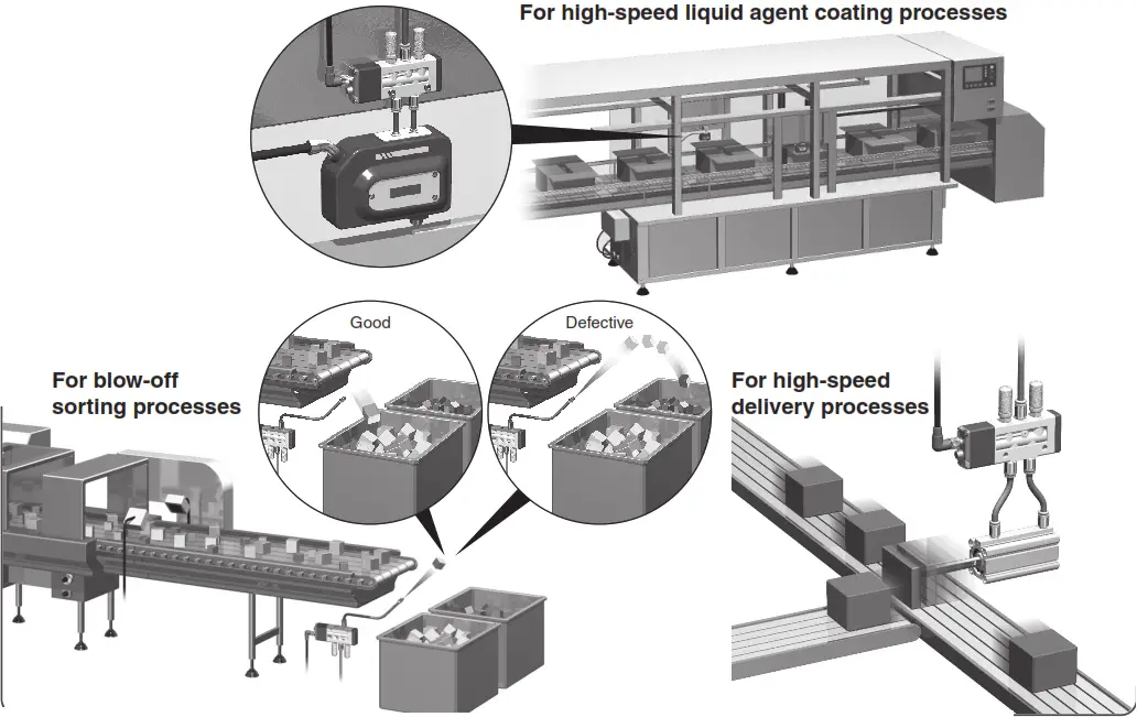
![]() Caution
Caution
The applications described here are for reference purposes only. Therefore, the function is not guaranteed. For actual use, please conduct a thorough evaluation and validation testing in order to determine the feasibility under your actual operating conditions.
DXT1215 Series
Valve Specifi cations
| Valve type | Rubber seal | ||
| Fluid | Air | ||
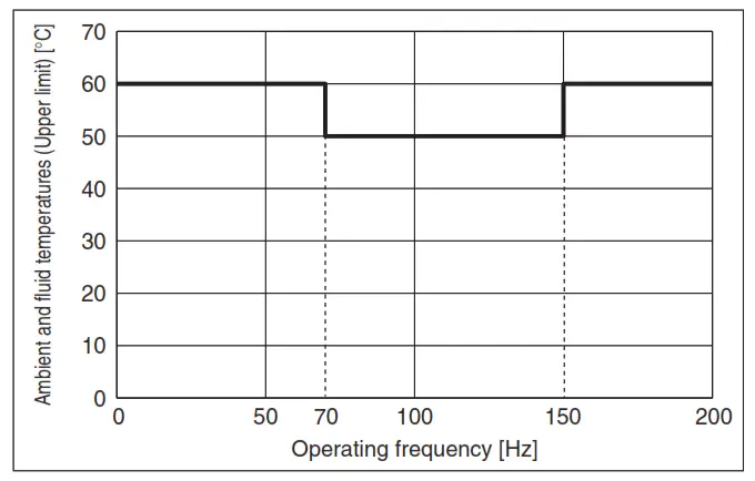
| Ambient and fluid temperatures [ C] | -10 to 60 (No freezing) 1 | ||
| The internal pilot operating pressure range [MPa] | 2-position single | 0.3 to 0.6 | |
| Response time [ms] 2 | ON: 2.5 OFF: 3 | ||
| Max. operating frequency [Hz] | 2-position single | 200 | |
| Manual override | Non-locking push type | ||
| Pilot exhaust type | Internal pilot | Common exhaust | |
| Lubrication | Not required | ||
| Mounting orientation*: 3 | Unrestricted | ||
| Impact/Vibration resistance 3 [M/S2] | 150/30 | ||
| Enclosure | IP67 | ||
| Electrical entry | M8 connector | ||
| Coil-rated voltage [V] | 24 VDC | ||
| Allowable voltage fluctuation [V] | -5% to +10% of the rated voltage | ||
| Power consumption [W] | DC | With power-saving circuit | 1.5* 4 [Inrush 6, Holding 1.5] |
| Surge voltage suppressor | Diode | ||
| Indicator light | LED | ||
| Weight [g] | 96 | ||
- The upper limits of the ambient and fluid temperatures vary depending on the operating frequency. (Refer to the graph below.) If a follow-up operation is performed at a duty ratio of 50% or higher, the upper limit value may change. Please contact SMC for further details.
- Based on the JIS B 8419:2010 dynamic performance test (Coil temperature: 20°C, pressure: 0.5 MPa, at the rated voltage)
- Impact resistance: No malfunction occurred when it was tested in the axial direction and at a right angle to both the main valve and the armature in both an energized and de-energized state, once for each condition. (Values at the initial period)
Vibration resistance: No malfunction occurred in a one-sweep test between 45 and 2000 Hz. The test was performed in both an energized and de-energized state in the axial direction and at a right angle to both the main valve and the armature. (Values at the initial period) - Only applicable to the power-saving circuit specification.
Flow Rate Characteristics
| Model | Port size | Valve flow rate characteristics | ||||
| 1, 5, 3 (P, EA, EB) | 4,2 (A, B) | |||||
| 1 →4/2 (P →A/B) | 4/2 →5/3 (A/B →E) | |||||
| C [dm3/(s•bar)] | b | C [dm3/(s•bar)] | b | |||
| DXT1215 | 1/8 | 1/8 | 1.3 | 0.37 | 1. | 0.23 |
∗ Calculation of effective area “S” and sonic conductance “C”: S = 5.0 x C
Operating Frequency
Valve Construction
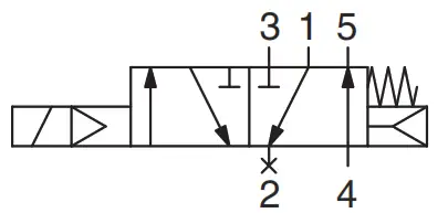
2-position single
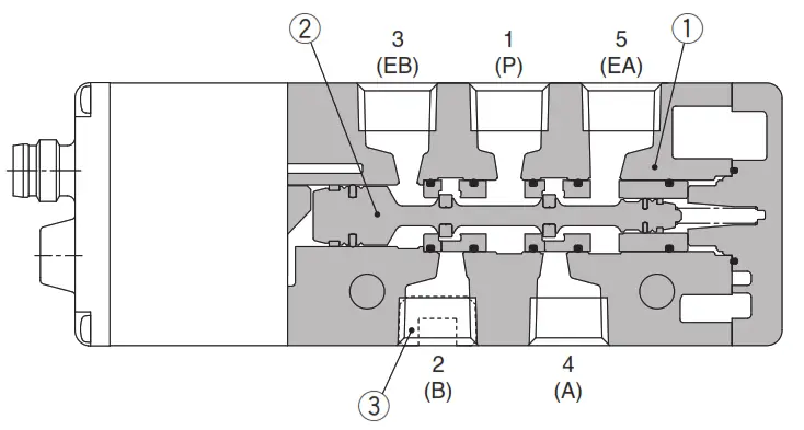
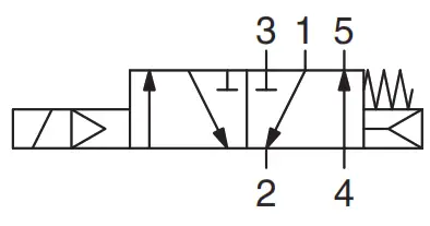
| 2-position single Standard 5-port specification | Made to Order 3-port specification (-X1) |
 |  |
Component Parts
| No. | Description | Material |
| 1 | Body | Aluminum die-casted |
| 2 | Spool assembly | Aluminum/FKM |
| 3 | Plug (For the -X1) | Steel |
How to Order Valves
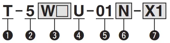
- Coil type
T: With a power-saving circuit - Rated voltage
5: 24 VDC - Electrical entry
M8 connector∗1 W WO With straight connector cable Without connector cable 

∗1 For the connector cable for M8 connectors refer to the back cover. For W, enter the cable length symbol in the . Please be sure to fi ll in the blank, referring to the back cover.
- Light/surge voltage suppressor
U: With light/surge voltage suppressor (Non-polar) - 4(A)/2(B) port size Thread piping
01: 1/8 - Thread type
Nil Rc F G N NPT - Made to Order
Nil — X1 3-port specifi cation
[2(B) port plug]∗ The 3 -the port specification is a specification with the 2(B) port plugged and closed. The 3(EB) port should be kept open for pilot exhaust.
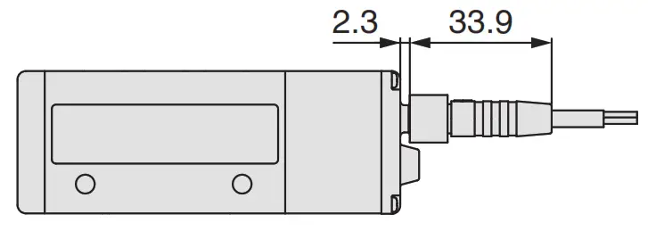
Dimensions
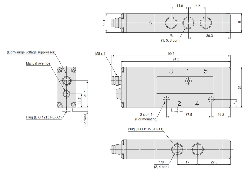
DXT1215 Series
Specific Product Precautions![]() Be sure to read this before handling the products. For safety instructions and 3/4/5-port solenoid valve precautions, refer to the “Handling Precautions for SMC Products” and the “Operation Manual” on the SMC website: https://www.smcworld.com
Be sure to read this before handling the products. For safety instructions and 3/4/5-port solenoid valve precautions, refer to the “Handling Precautions for SMC Products” and the “Operation Manual” on the SMC website: https://www.smcworld.com
Environment![]() Warning
Warning
Do not use the valves in atmospheres in which corrosive gases, chemicals, sea water, water, or water vapor are present or where there is direct contact with any of these.
Manual Override![]() Warning
Warning
The manual override is used for switching the main valve regardless of the valve’s electric signal. As the connected actuator will start operating due to this manual operation, be sure to confi rm that it is safe to do so beforehand.
- Non-locking push type
Push the manual override button all the way down.
Installation
![]() Caution
Caution
Even if the inlet pressure is within the operating pressure range, when the piping diameter is restricted due to size reduction of the supply port (P), the fl ow will be insuffi client. In such cases, the valve will not switch completely and the cylinder may malfunction.
Surge Voltage Suppressor
- With power-saving circuit (PWM circuit built-in type, non-polar type)
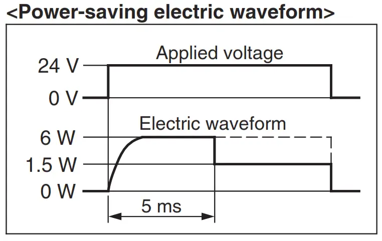
The power consumption has been reduced to approx. 1/4 of the startup power by eliminating the need for electrical current for holding. (Effective after being energized for more than 5 ms when the 24 VDC rated voltage is applied)
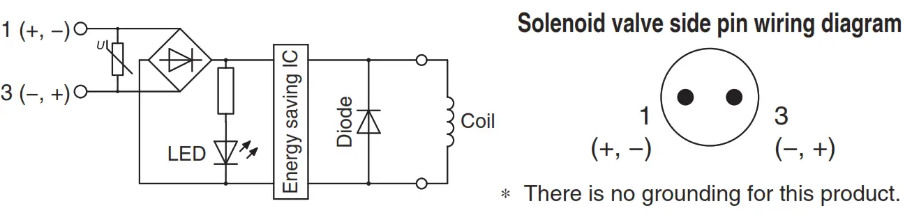
Operating principle
The circuit shown above reduces power consumption by eliminating the need for electrical current for holding in order to save energy. Refer to the electrical power waveform shown in the graph on the right.
Residual voltage of the surge voltage suppressor
If a diode surge voltage suppressor is used, there will be a residual voltage of approx. 1 V. Pay attention to the surge voltage protection on the controller side.
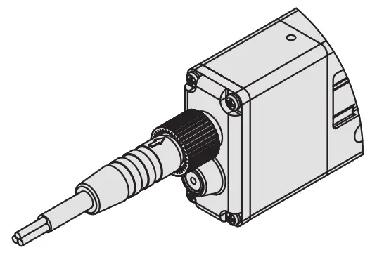
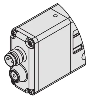
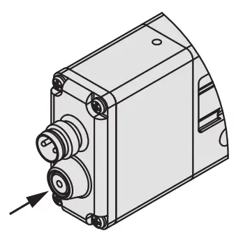
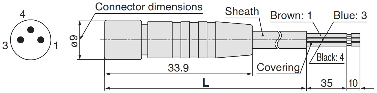
M8 Connector Type
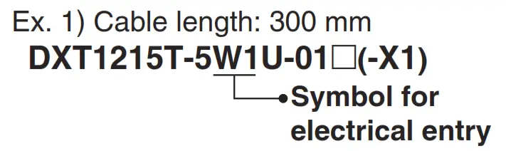
- Connector cable
· The connector cable for M8 connectors can be ordered as follows.
How to Order
1. To order a solenoid valve and the connector cable at the same time (The connector cable will be included in the shipment of the solenoid valve.)

| Symbol | Cable length [mm] |
| 1 | 300 |
| 2 | 500 |
| 3 | 1000 |
| 4 | 2000 |
| 5 | 3000 |
| 6 | 4000 |
| 7 | 5000 |
2. To order only the connector cable
| Cable length (L | Part no. |
| 300 mm | V100-49-1-1 |
| 500 mm | V100-49-1-2 |
| 1000 mm | V100-49-1-3 |
| 2000 mm | V100-49-1-4 |
| 3000 mm | V100-49-1-5 |
| 4000 mm | V100-49-1-6 |
| 5000 mm | V100-49-1-7 |
| Sheath O.D. | ø3.4 mm |
| Cover diameter | ø1.16 mm |
| Conductor area | 0.16 mm² |
Recommended M8 Connector Angle Type
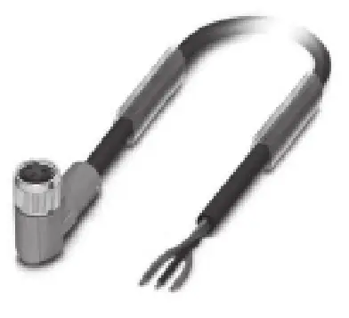
| Cable length | PHOENIX CONTACT | |
| Product no. | Order no. | |
| 1.5 m | SAC-3P-1,5-PUR/M 8FR | 1669738 |
| 3 m | SAC-3P-3,0-PUR/M 8FR | 0:00 |
| 5 m | SAC-3P-5,0-PUR/M 8FR | 1669631 |
| 10 m | SAC-3P-10,0-PUR/M 8FR | 1694169 |
Caution Phoenix Contact products should be ordered directly from the manufacturer or from its distributors.![]() Caution
Caution
- The M 8 connector type is IP 6 7 compliant (according to IEC 6 0 5 2 9 ) and protected against dust and water. However, it cannot be used underwater. Select an SMC connector cable (V100-49-1-) or an FA sensor type connector with M 8 threaded 3 -pin specifications conforming to Nippon Electric Control Equipment Association Standard NECA4202 (IEC 60947-5-2).
- Do not use a tool to mount the connector as this may damage it. Only tighten the connector by hand. (0.4 to 0.6 N·m)
- The application of excessive force on the cable connector will result in it no longer being able to satisfy the IP67 requirements. Please use caution and refrain from applying any force of 30 N or greater on the connector.
Failure to satisfy the IP67 requirements may result if using connectors other than those shown above or if the connector is insufficiently tightened.
![]() Safety Instructions Be sure to read the “Handling Precautions for SMC Products” (M-E03-3) and “Operation Manual” before use.
Safety Instructions Be sure to read the “Handling Precautions for SMC Products” (M-E03-3) and “Operation Manual” before use.
![]()
Akihabara UDX 15F,
4-14-1, Sotokanda, Chiyoda-ku, Tokyo 101-0021, JAPAN
Phone: 03-5207-8249 Fax: 03-5298-5362
https://www.smcworld.com
© 2022 SMC Corporation All Rights Reserved
Specifications are subject to change without prior notice
and any obligation on the part of the manufacturer.
Printing AT 590KS Printed in Japan.


