
Unity Lab Services Freezer ULT Peek TC Diagnostics User Guide
Product Overview
| T/C | Reading | Indication: No Problem Indicated |
| TC #10 | 35 to -45C | The TC is in a normal operating range. TC #10 are warmer than when the first stage is running without the second stage energized, showing that the first stage is receiving a heat load from the second stage, which is how the cascade system is supposed to work. |
| TC #3 | -86 to -95C | TC #3 is cold showing that the interstage condenser (Heat Exchanger) is working well. TC #4 is colder than TC #3, reflecting proper operation of the cascade system with a flooded evaporator. |
| TC #4 | -86 to -95C | The delta T between TC #3 and TC #4 is about 5 degrees F. If the door is opened, product loaded, or room ambient increases, the TC readings and delta T, along with the cabinet temp, may also increase until the system removes the added heat load. If the unit is cycling the readings will fluctuate, which is why stabilized Bottom Out mode is used for these readings. |
| Display Temp. | -86 to 95C | Acceptable Bottom Out Temperature. |
| TC #10 | -35 to -50C | First stage appears to be running normally or too cold.
|
| TC #3 | – 86 to -95C | TC #3 shows a large heat load in the second stage, but ifs not getting transferred to the first stage, indicating a lack of refrigerant flow. Four main reasons: (1) Leak, (2) Undercharge, (3) Lack of efficiency, (4) An obstruction to flow. |
| TC #4 | -40 to -75C | Manifold Gauge Diagnostics; second stage flow problems. Hint: If there’s a leak, you will see temperatures continue to change and warm. If it’s a bad pump or restriction, it will probably maintain. |
| Display Temp. | Unable to achieve set point | A steady or slightly fluctuating cabinet temperature. |
An oil logging problem is a type of restriction, due to too much refrigerant oil getting to the cap tube and evaporator, and then becoming thick, or even solid, at these cold sections of the system. It can be caused by a large load of warm product placed in the cabinet, lack of first stage performance, failed oil separator, contamination build up over time, or failure to defrost the cabinet as needed. It can be constant or varying. This is because the oil logging gets worse as the cabinet cools, which causes the cabinet to warm, which thaws the oil allowing more flow and the cabinet will start to cool again, repeating the cycle. The cabinet temperature will vary around -55°C to -75°C over a period of a day or two, warming then cooling, then warming then cooling, continually. This cycle will not continue if the problem is a leak, as in that case, the cabinet will get continually warmer. Defrosting the cabinet over a period of 48 hours, then restarting it might solve the problem. Back-flushing the system, replacing the oil separator, then recharging is the definite solution. Refer to Manifold Gauge Diagnostic Procedures, Section 6.17 of this manual for further symptoms using gauges.
A continuously increasing restriction can look like a leak, as the restriction gets more severe. Refer to Manifold Gauge Diagnostic Procedures, Section 6.17 of this manual for further instructions before making this determination.
Onboard Instrumentation
| Sensor | Location | Type | Detail |
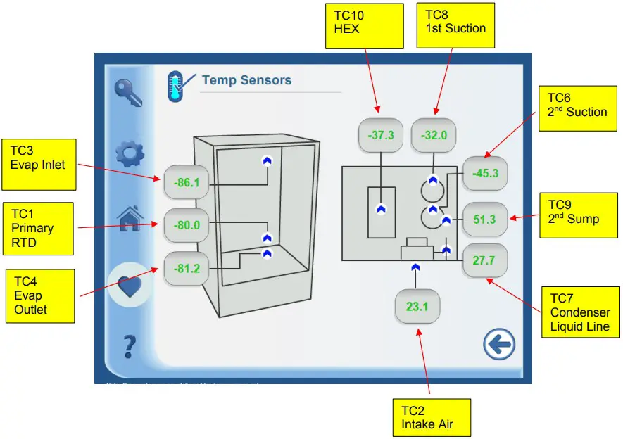
| RTD1 | Cargo Area | RTD, 1000 Ohm | Back wall, center. Near the end of the evaporator. |
| TC #1 | First Stage Suction | T-type thermocouple | On suction tube at compressor |
| TC #2 | Condenser Air Inlet | TT-type thermocouple | In air stream in front of condenser coil |
| TC #3 | Evaporator In | TT-type thermocouple | Top of cabinet; foamed in place, |
| TC #4 | Evaporator Out | T-type thermocouple | Bottom of cabinet, foamed in place. |
| TC #5 | Blank; Reserved For Future Use | ||
| TC #6 | Second Stage Suction | TT-type thermocouple | On suction tube at compressor |
| TC #7 | Condenser Out (Liquid Line) | TT-type thermocouple | Immediately downstream from the condenser coil. |
| TC #8 | Blank; Reserved For Future Use | T | |
| TC #9 | Stage Sump | IT-type thermocouple | |
| TC #10 | BPHX | Two T-type thermocouples | Installed at the center of the BPHX. Two sensors installed; one for backup. |
| Sensor | Location | Type | Main BoardLocation | Wire/BandColor | Part Number |
| RTD I | Back Wall Inside Cabinet | RID, 1000 Ohm Red/White | J18 | Red/White | 315206H01 |
| TC #1 | First Stage Suction | TC, Type T, Stranded | J14 | Brown | 315204H01 |
| TC #2 | Condenser Air Inlet | TC, Type T, Stranded, | J14 | Red | 315204H02 |
| TC #3 | Evaporator Inlet | TC, Type T, Stranded, | J14 | Orange | 315204H03 |
| TC #4 | Evaporator Out #1 | TC, Type T, Stranded, | J14 | Yellow | 315204H04 |
| TC #6 | Second Stage Suction | TC, Type T, Stranded, | J14 | Blue | 315204H06 |
| TC #7 | Condenser Out (Liquid Line) | TC, Type T, Stranded, | J14 | Violet | 3152041-107 |
| TC #9 | Second Stage Sump | TC, Type T, Stranded, | J14 | White | 315204H09 |
| Lc #10 | BPHX | TC, Type T, Stranded, | J14 | Black | 315204H10 |
![]()


