Solid RF XD Building Force Cell Phone Signal Booster
Working Diagram (How It Works)
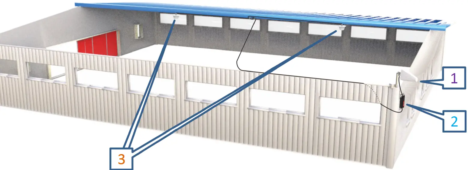
- The outdoor antenna catches the signal from the tower.
- Sends signal to the booster through a coax cable.
- The booster amplifies the signal then rebroadcasts the signal indoors to all mobile devices within range.
- The system also works in reverse; amplifying outgoing signal back to the tower.
The size and the coverage area and the strength of the boosted signal are directly related to two key factors:
- Signal strength received by the outdoor unit. So, setting up the outside unit where the signal is the strongest will provide the best results.
- Distance of separation between the outdoor unit and the indoor unit.
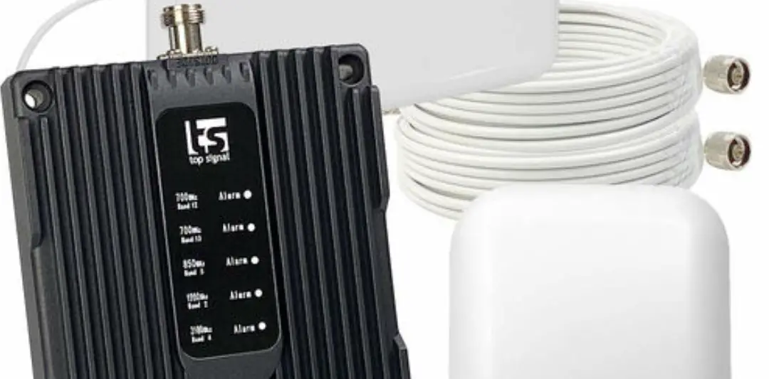
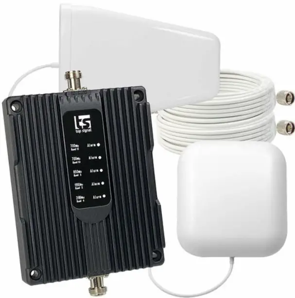
Package Contents
The kit includes the following items
- Outdoor Antenna, Indoor Antenn
- Booste
- Power supply
- Splitte
- 4*45 ft & 1*15 ft of RG11 cable
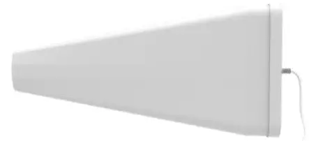 Outdoor Antenna
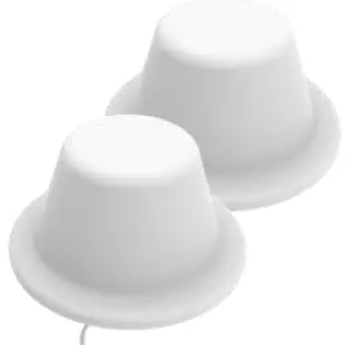
2 Indoor Antenna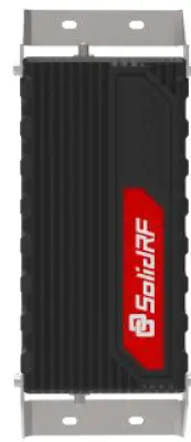
Booster Power
supply Splitter&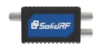
Power Feeder
RG11 cable
Signal transmission loss and power level
Coverage area ability
Note
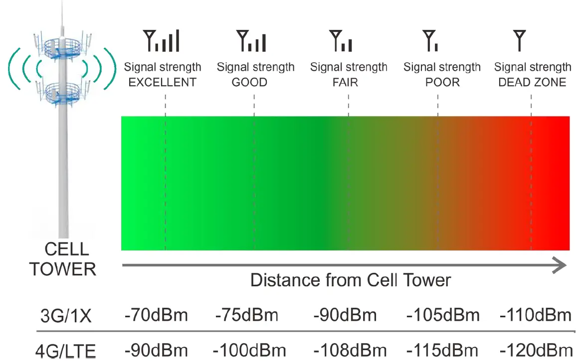
FCC regulations limit the amplification of all cell phone boosters in order to prevent damage to the telecommunications infrastructure. Therefore, the maximum coverage area of a booster depends on the original power level of the signal captured by the outdoor unit. Not recommended when outdoor signal strength is less than -110dbm(3G/1x) or -120dBm(4G/LTE). The resulting coverage area of the boosted signal will be prohibitively small.
| Power level at the outdoor antenna location | Coverage Area @ One Antenna (sq. ft.) | Coverage Area @ Two Antenna (sq. ft.) |
| Strong 5 bars on the cellphone) | 6,000 | 12,000 |
| Medium 3~4 bars on the cellphone | 3,000 | 6,000 |
| Weak 1~2 bars on the cellphone | 800 | 1,500 |
Preparation
Find a cell tower nearby
There are a variety of resources available online, here are some third party websites and app recommended. Use these to locate your nearest cell tower, either by street address of GPS coordinates.
For U.S. websites
www.antennasearch.com/
www.cellmapper.net/
www.cellreception.com/towers
For Canada website
www.cellmapper.net/ 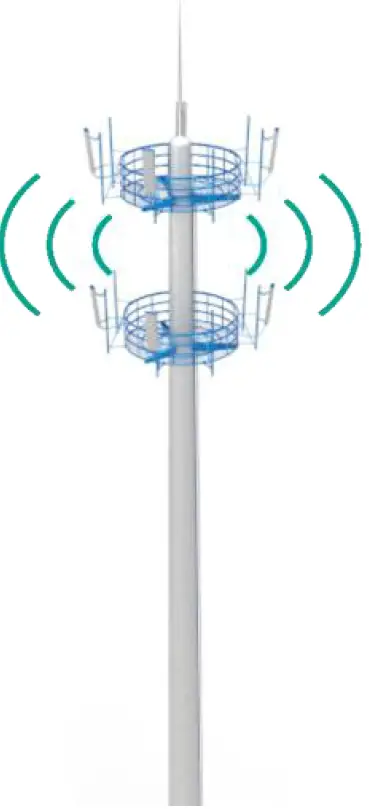
Find The dBm Reading On Your Phone
Having an accurate measurement of signal strength in decibels (dBm) is crucial when installing your system. Decibels accurately measure the signal strength you are receiving. Test both 3G and 4G signal for best results by turning the LTE off in the carrier settings of your device.
iPhone
Need to download third part APP
Android
Settings > About Phone > Status or Network > Signal Strength or Network Type and Strength (exact options/wording depends on phone model).
Note
Turn off your cell phone’s WiFi to ensure you are checking the cellular connection. The dBm reading will be refreshed every 30-60 seconds. Want faster results? Once you have a reading, turn on airplane mode. Wait 15 seconds. Turn off airplane mode. The signal strength reading is refreshed. You Will Need (make sure the following things and tools are prepared and ready for your installation.
- 2~3 hours.
- 2 people a person to help with antenna calibration.
- Drill (if routing cable through wall.
- Recommended: Power Strip with surge protection.
Test Installation
We STRONGLY recommend doing a test installation before finalizing the installation. Doing a test installation of your cell phone booster ensures that you will get the optimal performance from your system.
Measure the Signal Strength Inside your Home
- Test your current signal strength in multiple locations throughout the home.
- Record the current signal strength in the table provided for reference.
| No | Location | Record(dBm) |
| 1 | ||
| 2 | ||
| 3 | ||
| 4 | ||
| 5 |
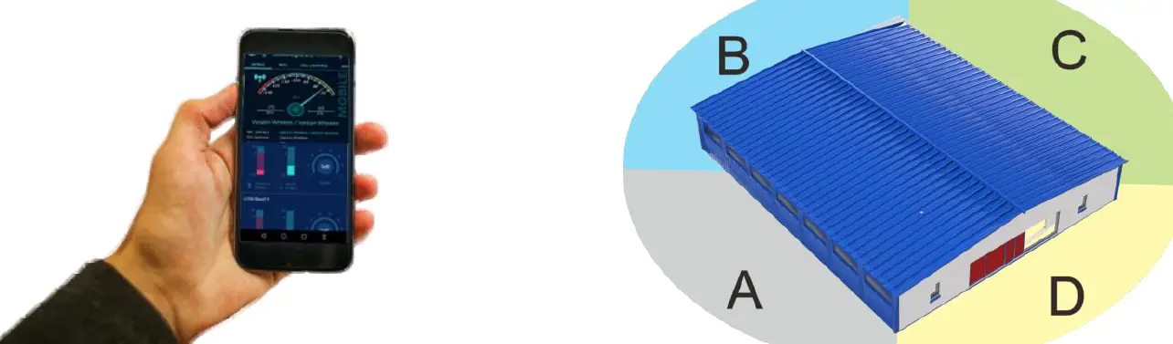
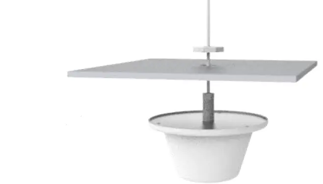
Select the Location for the Inside Antenna
The indoor antenna is a omni-directional antenna. Choosing a location that central the entire target area will help maximize your coverage.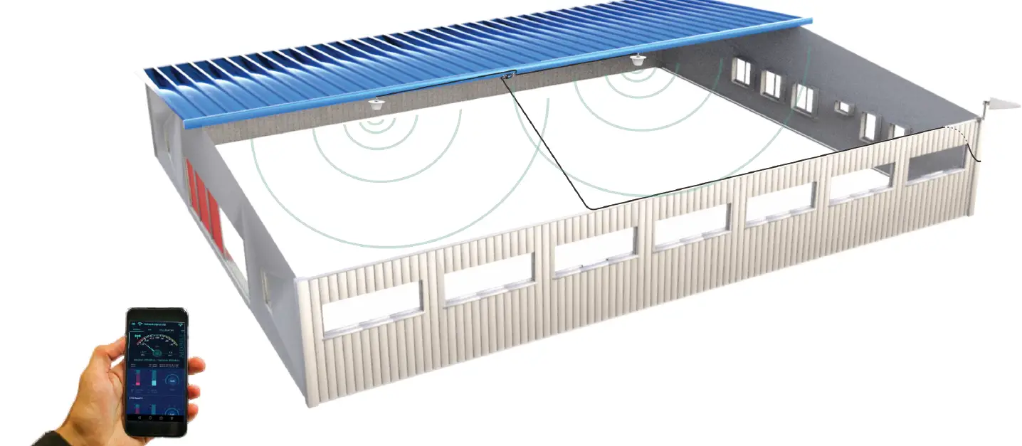
Select the Location for the Outside Unit
- This is the most critical step and will determine the overall performance of the booster system.
- Using the same method described in Step 1, walk around the outside of your home and test the signal strength. Determine where you have the strongest signal the dBm reading is closest to zero.
- Generally, the strongest signal will be located on the side of your home facing the nearest cell tower. Keep in mind, the signal strength at ground level may be different from the signal strength at or above the roofline due to obstructions trees, other buildings, etc that block the incoming signal. In most situations, the strongest signal is found about 15 feet above the ground on the side of your home facing the nearest cell tower.
Caution
The height of the outside antenna should never exceed the highest point of your home. This is a precaution against damage and safety concerns caused by lightning strikes to the outside unit. In order to achieve the best performance, try to maximize the distance between the inside and outside antenna. Ensure that the outside antenna is pointed away from where you plan to install the inside antenna. Self-oscillation may occur if the outside antenna is pointed over the location of the inside antenna.
| No | Location | Record(dBm) |
| 1 | ||
| 2 | ||
| 3 | ||
| 4 | ||
| 5 |
Temporarily Mount the Outside Antenna
Use one of the tow options to mount the outside antenna on your roof on the side of the house with the strongest signal.
Caution
In order to achieve the best signal coverage effect, there is a certain distance requirement between the indoor and outdoor units. Make sure the inside and outside units are facing away from each other. Minimum Required Separation Distance Between Indoor and Outdoor Antenna 45 ft (15 meters) horizontal distance 6 ft (2 meters) vertical distance(As far as possible) Make sure to meet the Minimum Separation Requirements while at the same time mounting the outside unit in the location with the strongest signal.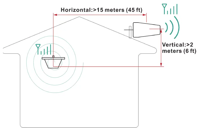
Connect the System
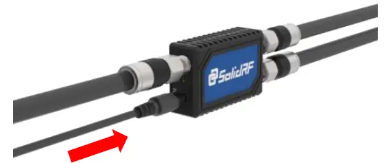
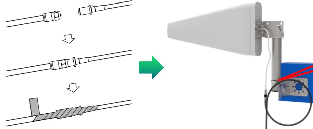
Connect the outside antenna to the 15 feet RG11 cable, fix the connector(In order to avoid internal damage of the antenna connector due to gravity or pulling the cable)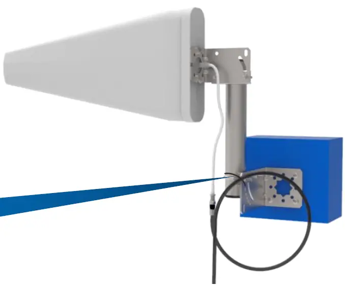
Secure the cable near the antenna to prevent cable damage caused by wind shaking
Connect the outside antenna to the “OUTSIDE port of booster.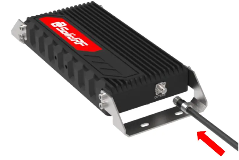 Connect the 45 ft RG11 cable to the booster at the INSIDE port.
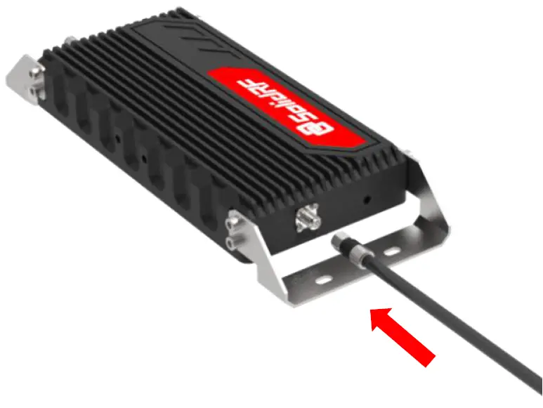
Connect the other end of the coax cable to splitter at the “INPUT” port, and two inside antennas’ cables connect to the other side port.
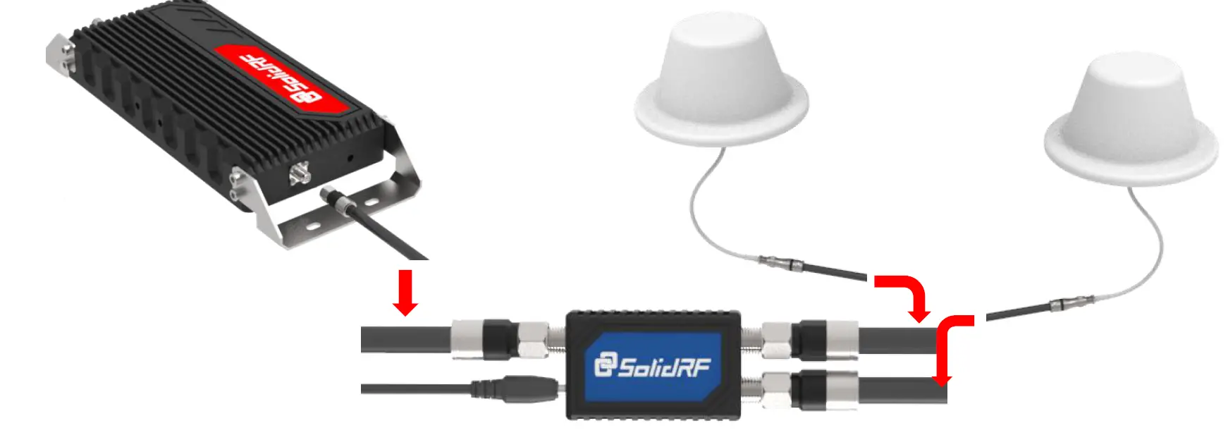
Connect the other end of the coax cables to the panel antennas.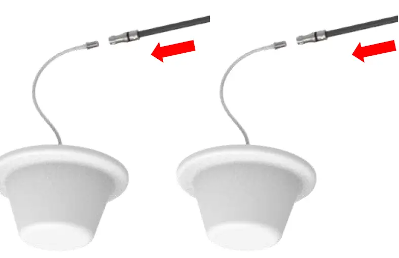
Plug in the power adaptor and connect it to the nearest power outlet surge protector recommended.
Evaluate the Effects
Now that the booster is up-and-running, re-test the signal strength inside your home at the same locations from Step 1. If the number is higher (dBm reading is closer to zero) than the original reading, your booster is working. If your signal is not stronger, check the LED lights on the booster.
| No | Location | Record(dBm) |
| 1 | ||
| 2 | ||
| 3 | ||
| 4 | ||
| 5 |
Decibel Gain v. Power Amplification/Distance/Coverage area
| Decibel Gain | Power Amplification (times) | Distance Enhance (times) | Coverage Enhance (times) |
| 6 | 4 | 2 | 4 |
| 10 | 8 | 3 | 9 |
| 20 | 100 | 8 | 64 |
| 30 | 1000 | 32 | 900 |
Note
Decibel Gain and Power Amplification may vary depending on the specifics of your situation. Different building materials and other obstructions in your home will result in different outcomes.
Finalizing Outdoor Antenna Installation
Once you have tested the performance of the signal booster and made all necessary adjustments, it’s time to finalize the installation.
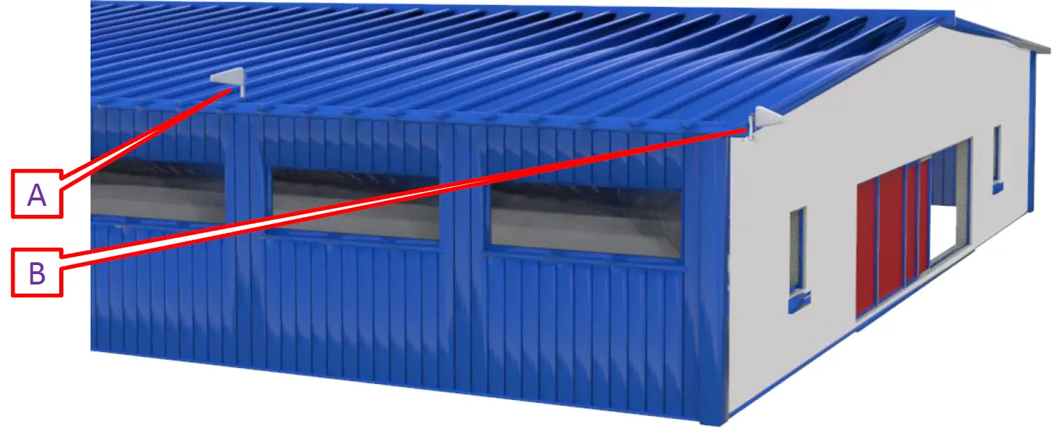
Outdoor Antenna Installation
Make sure that the outside antenna is mounted at least 3 feet away from any windows.
Option A
Outside Roof Pole Mount Best Choice Use an existing pole to mount the outdoor unit in the optimal signal location. Use the picture for reference.
Option B
Mounting on Side of Wall Second Choice.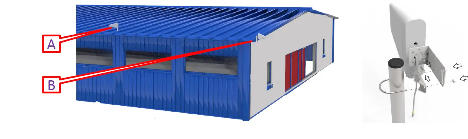
Caution
In particular, cables for outdoor antenna locations must be fixed. Otherwise, the internal wires of the cable will be pulled off after the wind has been shaken for a long time. The amplifier will not receive the signal and the system will fail completely.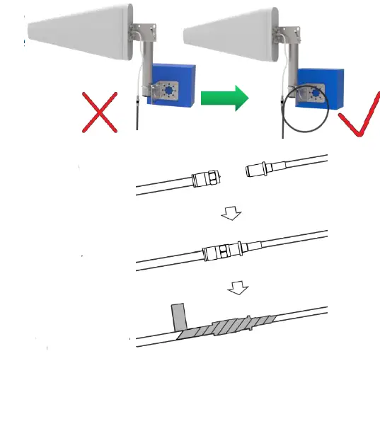 It is best to have the cable around a single turn shape and then fix it. Long-term rain or moisture erosion can damage the electrical characteristics of outdoor antenna connectors. Make sure connectors are well screwed in and seal the connectors with glued tape.
Finalizing Indoor Antennas Booster Installation
 Choose right position for the indoor antenna 20 cm away from facing any other metallic objects 50 cm away from any windows The inside antenna should be central the location of the signal dead zone/weak signal area inside the building. Mount the inside antenna.
Finalizing Booster Installation
Mount the booster: Keep away from heat and don’t cover booster. Booster will about 30 degrees Fahrenheit higher than the ambient temperature, which is a normal phenomenon.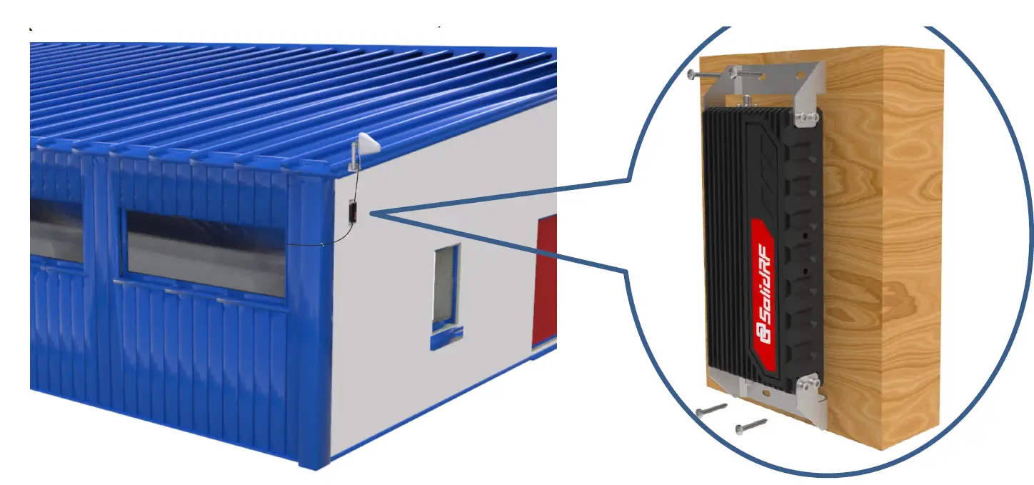
Finalizing and Securing Cable Route
Find the best route for the cable. Follow the lines of your home to hide the cable in eaves or between the soffit and the exterior wall. If needed, cable clips can be purchased at most hardware stores.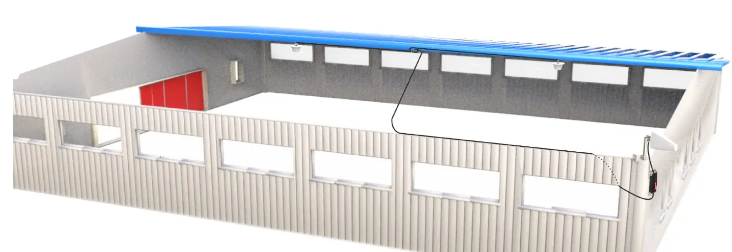
Whether the cable is properly secured is very important for the entire system. In most cases, the customer found that the booster did not work after working for a period of time because the cable was not installed securely. Carefully arrange the cable along the outside of the building and ensure that there are no folds or kinks. Fix the cable at each corner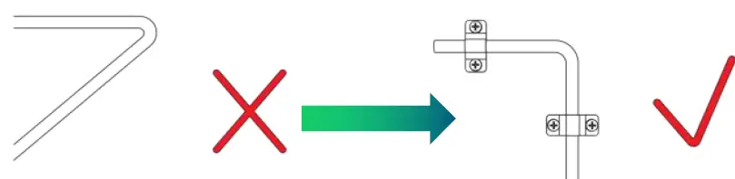
Seal and Fix the Connector
Secure the cable near the antenna to prevent cable damage caused by wind shaking
Properly Handle Excess Cables
If the coiled cable is too close to the antenna or booster, the system will be unstable. Make sure these coiled cables are more than 6 feet(2 meters) from the antenna or booster.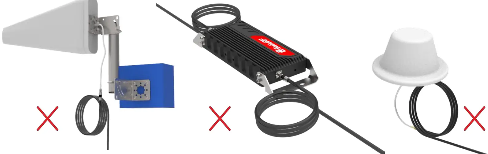
Make sure these excess coiled cables are more than 6 feet(2 meters) from the antenna or booster can make your system work more stable.

Quick Trouble shooting
Correct functioning
Power Light should be solid green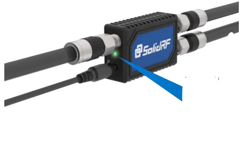 Solid green will be illuminated after the power is turned on.
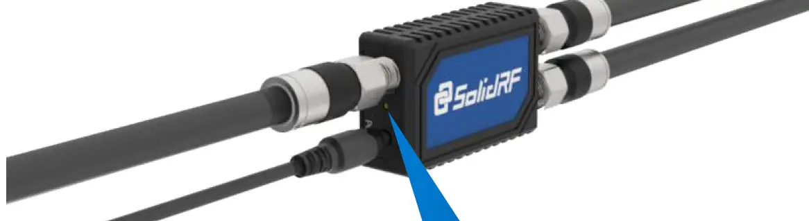
No Signal Improvement
If the LED is off please check power. Ensure the DC power is plugged in and the LED Power Light is lighting.
Solid off
If the LED is solid RED check cable connections. Ensure the feeder, Booster and outdoor antenna are securely connected to the coax cable.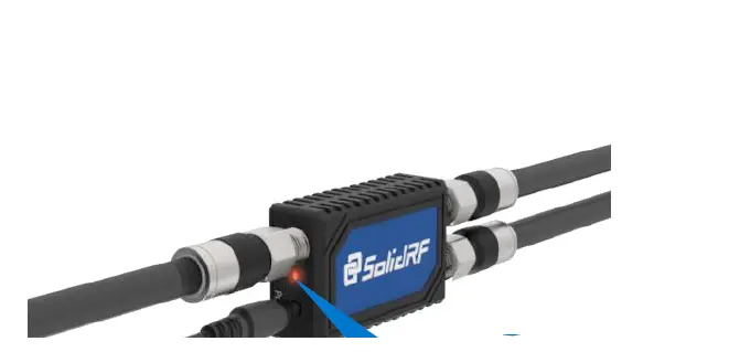
Solid Red after the power is turned on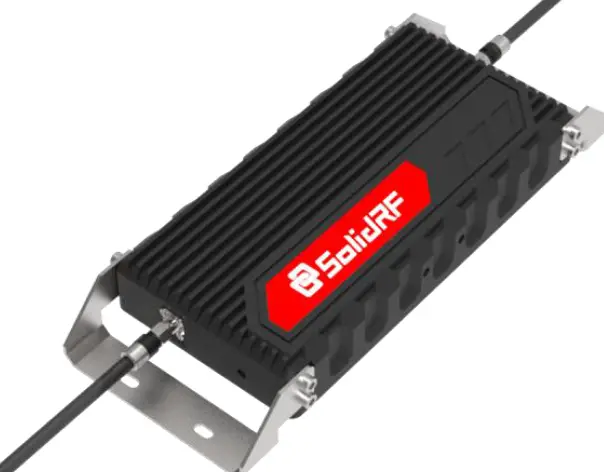
Double check the location of outdoor and indoor units. Make sure that the Minimum Separation Requirements have been met. Make sure that the outside antenna is not pointed towards the inside antenna.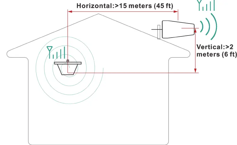
Minimum Required Separation Distance Between Indoor and Outdoor Unit: Horizontal Distance = 45 feet (15 meters) Vertical Distance = 6 feet 2 meters As far as possible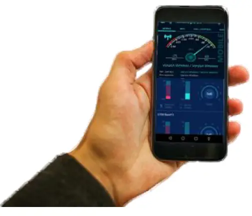
Check incoming signal level at outdoor unit position. Usage of a booster is not recommend when the outdoor signal is less than -110dbm(3G/1x) or -120dBm (4G/LTE).
Technical Specification
| Frequency (MHz) | LTE (band 12) | LTE (band 13) | Cellular (band5) | PCS (band 25/2) | AWS (band 4) | |
| Uplink | 698-716 | 776-787 | 824-849 | 1850-1915 | 1710-1755 | |
| Downlink | 728-746 | 746-757 | 869-894 | 1930-1995 | 2110-2155 | |
| Gain | Uplink | 65 | 65 | 65 | 68 | 68 |
| Downlink | 68 | 68 | 68 | 70 | 70 | |
| Output power | 26dBm(Uplink)/10dBm(Downlink) | |||||
| Noise figure | <5dB | |||||
| In-band Flatness | <9dB | |||||
| Weight | 2.65Kg | |||||
| EIRP | 1W | |||||
| Impedance | 50 ohm | |||||
| Operating temperature | -5°~60° | |||||
| Current | ≦1.5A(6V DC) | |||||
| Dimension(mm/in) | 325*155*45 mm / 13*6*1.7 in | |||||
WARRANTY
The Booster is covered under a three-year product warranty for failures or defects that result from craftsmanship and/or materials. Dated proof of purchase should be retained for use in warranty cases. Contact the retailer/reseller directly with any warranty issues, or alternatively contact the manufacturer in cases where the reseller is no longer available to handle warranty claims. In cases where the reseller is unavailable, the product may be returned to the manufacturer at the consumer’s expense, with a dated proof of purchase and a return authorization letter which can be attained by contacting Solid RF. This warranty does not apply to any signal booster components determined by Solid RF to have been subjected to misuse, abuse, neglect, tampering, or mishandling that result in damages to the physical or electronic properties of the product. Refurbished products that have been recertified to conform to product specifications may be used for product replacements.
DISCLAIMER
The information provided by Solid RF is believed to be complete and accurate, to the best of our knowledge. However, no responsibility is assumed by Solid RF for any business or personal losses arising from the use of the information herein contained, or for any infringements of patents or other rights of third parties that may result from its use.
Safety Guidelines
To uphold network protection standards and ensure compliance, all active cellular devices must maintain a separation distance of at least six feet between the inside unit antenna and outside unit antenna and at least four feet of separation distance from the inside unit. Use only the power supply provided in this package. Use of a non-Solid RF product or accessory may result in damage to the equipment or components of the equipment. The inside unit is designed for use in an indoor, temperature-controlled environment (less than 100 degrees Fahrenheit). It is not intended for use in attics or similar locations where temperatures may be in excess of that range.
RF Safety Warning
Any antenna used with this device must be located at least 8 inches from all persons. FOR MORE INFORMATION ON REGISTERING YOUR SIGNAL BOOSTER WITH YOUR WIRELESS PROVIDER, PLEASE SEE BELOW
Sprint: http://www.sprint.com/legal/fcc boosters.html
T-Mobile/MetroPCS: https://support.t-mobile.com/docs/DOC 9827
Verizon Wireless:http://www.verizonwireless.com/wcms/consumer/register signal booster.html
AT&T: https://securec45.securewebsession.com/attsignalbooster.com/
U.S. Cellular:http://www.uscellular.com/uscellular/support/fcc booster registration.jsp
If you have any questions or concerns when installing or operating your cell phone booster, please email us at
US: [email protected]
Canada: [email protected]
Or call our customer service number
Office (435) 319-6858
Toll Free (877) 579-7878
Description of network protection features
This booster including safeguards to protect the cellular network from interference. Each Signal Booster is individually tested and factory set to ensure FCC compliance.
- The Signal Booster cannot be adjusted without factory reprogramming or disabling the hardware.
- The Signal Booster will amplify, but ONLY incoming and outgoing signals in order to increase coverage of authorized frequency bands.
- If the Signal Booster Is not in use for five minutes, It will reduce gain until a signal Is detected.
- If a detected signal is too high in a frequency band, or if the Signal Booster detects an oscillation, the Signal Booster will automatically turn the power off on that band.
- For a detected oscillation the Signal Booster will automatically resume normal operation after a minimum of 1 minute.
- After S times consecutive such automatic restart s, if the detected oscillation still remains, any problematic bands are permanently shut off unti restarted by reconnecting power supply to the Signal Booster.
- Noise power, gain, and linearity are maintained by the Signal Booster’s microprocessor.
This is a CONSUMER device
BEFURE USE ,you MUST REGISTER THIS DEVICE with your wireless provider and have your provider’s consent .Most wireless provider consent to t he use of signal boosters .Some provider may not consent to the use of this device on their network .If you are unsure, contact your provide. You MUST operate this device with approved antenna and cables as specified by the manufacturer .Antennas MUST be installed at least 20cm Sine hes from any person. You must cease operating this device immediately if requested by the FCC or a licensed wireless service provider.
WARNING
E911 location information may not be provided or may be inaccurate for calls served by using this device. This device may be operated ONLY In a fixed location for
In building use.This device complies with Part 15 of FCC Rules. Operation is subject to the following two conditions his device may not cause harmful interference. and this device must accept any interference received, including interference that may cause undesired operation.Contact information for providers.A subscriber must have the consent of a wireless provider to operate a consumer signal booster. Please register your booster with your wireless service provider, refer to contact information for providers:
Sprint; [email protected]
T-Mobile:
www.T-Mobile.com/BoosterRegistration
AT&T: https://securec45.securewebsession.com/attsignalbooster.com/
FCC Radiation Exposure Statement
This equipment complies with FCC radiation exposure limits set forth for an uncontrolled environment . This transmitter must not be co‐located or operating in conjunction with any other antenna or transmitter. This equipment should be installed and operated with minimum distance 20cm between the radiator & you body. Any Changes expressly or modifications not approved by the party responsible for compliance could void the user’s authority to operate the equipment.
Safety Guidelines
To uphold network protection standards and ensure compliance, all active cellular devices must maintain a separation distance of at least six feet between the inside unit antenna and outside unit antenna and at least four feet of separation distance from the inside unit. Use only the power supply provided in this package. Use of a non Solid RF product or accessory may result in damage to the equipment or components of the equipment. The inside unit is designed for use in an indoor, temperature controlled environment less than 100 degrees Fahrenheit. It is not intended for use in attics or similar locations where temperatures may be in excess of that range.
RF Safety Warning
Any antenna used with this device must be located at least 8 inches from all persons.This is a CONSUMER device BEFORE USE you MUST REGISTER THIS DEVICE with your wireless provider and have your provider’s consent .Most wireless provider consent to the use of signal boosters .Some providers may not consent to the use of this device on their network .If you are unsure ,contact your provider. n Canada, BEFORE USE You must meet all requirements set out in ISED CPC-2-1-05.You MUST operate this device with approved antenna and cables as specified by the manufacturer .Antennas MUST be installed at least 20cm (8inches) from(i.e. , MUST NOT be installed within 20 cm of)any person. You MUST cease operating this device immediately if requested by the I or a licensed wireless service provider.
WARNING
E911 location information may not be provided or may be inaccurate for calls served by using this device. This device may be operated ONLY in a fixed location for in-building use. CPC‐2‐1‐05 Zone Enhancers Spectrum management and telecommunications http://www.ic.gc.ca/eic/site/smt‐gst.nsf/eng/sf08942.html
| Mobile phone is the minimum distance to use indoor antenna | |
| Inside server antenna types | Minimum separation distances D (m) |
| Ceiling mounted e.g., dome type antennas | 2 |
| Wall mounted i.e. panel or other typeantennas | 1.0 or 2* |
| Table top antennas | 1.0 |
Warnings and Recommendations
This consumer booster is for Consumer use only Unauthorized antennas, cables, and/or coupling devices are prohibited by FCC regulations. Please contact FCC for details: 1·888·CALL·FCC. Outside antenna orientation must be back side of inside antenna is to prevent the indoor antenna receiving the signal emitted by outside antenna. Otherwise it will cause self-oscillation of booster. RF safety, any antenna used with this device must be located at 20 cm IS inches away from persons or by bystanders.It will damage the mobile device and the booster if connect them with a cable directly. Use the power supply provided by Solid RF only. Other power supplies may cause damage of the booster. Antenna installation is restricted to 10 meters or less height above ground. even if the antenna is installed inside when used with a mobile device t hat operates in the 1710-1755 MHz band. Violation of this requirement may subject the owner of the booster to potential FCC enforcement actions. Never point the front of a directional antenna toward the inside antenna. verify that both the outside antenna :md the inside antenna are connected to the booster before powering up the booster.
RF Exposure
The manufacturer’s rated output power of t his equipment is for single carrier operation. For situations when multiple carrier signal5 are present, the rating would have to be reduced by 3.5 dB, especially where the output is re-radiated and can cause interference to adjacent band users. This power reduction is to be by means of input power or gain reduction and not by an attenuating at the output of the device. This device complies with Industry Canada license-exempt RSS standard . Operation is subject to the following two conditions this device may not cause interference, and this device must accept any interference, including interference that may cause undesired operation of the device. This system has been evaluated for RF Exposure per RSS-102 and is in compliance with the limits specified by Health Canada Safety Code 6. The system must be installed at a minimum separation distance from the antenna to a general bystander of 8 inches 120 cm) to maintain compliance with the General Population limits.
Antenna Kitting Information
| Component |
Type specification | Gain/Loss | Manufacturer | |||||||||||
| LTE‐707 | LTE‐781 | 800MHz | 1900MHz | 1700MHz\2100MHz | ||||||||||
| Outside Cable | LMR240 45Feet | 2.9dB | 3.15dB | 3.38dB | 4.87dB | 4.87dB\5.2dB | Suirongcable | |||||||
| Outside Cable | SRLMR400‐30NN 30Feet | 1.9dB | 1.9dB | 1.95dB | 2.9dB | 2.55dB\2.9dB | Suirongcable | |||||||
| Inside Cable | RG6FF 90Feet | 4.3dB | 4.6dB | 5dB | 7.6dB | 6.6dB\8.4dB | Suirongcable | |||||||
| Inside Cable | RG6FF 75Feet | 3.6dB | 3.8dB | 4.2dB | 6.3dB | 5.5dB\7dB | Suirongcable | |||||||
| Inside Cable | RG6FF 60Feet | 2.9dB | 3.0dB | 3.3dB | 5dB | 4.4dB\5.6dB | Suirongcable | |||||||
| Inside Cable | RG6FF 45Feet | 2.2dB | 2.3dB | 2.5 dB | 3.8 dB | 3.3 dB\4.2dB | Suirongcable | |||||||
| Inside Cable | LMR240 90Feet | 5.85dB | 6.3 dB | 6.75 dB | 9.9 dB | 9.9dB\10.35dB | Suirongcable | |||||||
| Inside Cable | LMR240 75Feet | 4.88dB | 5.25dB | 5.63dB | 8.25dB | 8.25\8.63 dB | Suirongcable | |||||||
| Inside Cable | LMR240 60Feet | 3.9dB | 4.2dB | 4.5dB | 6.6dB | 6.6 dB\6.9 dB | Suirongcable | |||||||
| Inside Cable | LMR240 45Feet | 2.9dB | 3.15dB | 3.38dB | 4.87dB | 4.87dB\5.2dB | Suirongcable | |||||||
| Inside Cable | SRLMR400‐30NN 30Feet | 1.9dB | 1.9dB | 1.95dB | 2.9dB | 2.55dB\2.9dB | Suirongcable | |||||||
| Inside Cable | SRLMR400‐75NN 75Feet | 4.2dB | 4.2dB | 4.4dB | 6.1dB | 5.8dB\6.5dB | Suirongcable | |||||||
| Inside Cable | SRG58‐30FN 30Feet | 4.5dB | 4.5dB | 4.9dB | 7.6dB | 7.2dB\8dB | Suirongcable | |||||||
| Inside Cable | SRLMR400‐20NN 20Feet | 1.3dB | 1.3dB | 1.35dB | 1.8dB | 1.8dB\1.9dB | Suirongcable | |||||||
| Inside Cable | SRG58‐15FN 15Feet | 2.35dB | 2.4dB | 2.56dB | 3.9dB | 3.7dB\ 4.1dB | Suirongcable | |||||||
| Inside Cable | SRLMR400‐30NN 30Feet | 1.9dB | 1.9dB | 1.95dB | 2.8dB | 2.55dB\2.9dB | Suirongcable | |||||||
| Outside Antenna | ANT050701 | 7dBi | 7dBi | 7dBi | 10dBi | 10dBi\10dBi | Shenzhen Dachi Communications Co., Ltd. | |||||||
| Outside Antenna | ANT010901 | 9dBi | 9dBi | 9dBi | 9dBi | 9dBi | Shenzhen Dachi Communications Co., Ltd. | |||||||
| Outside Antenna | ANT010701 | 9dBi | 9dBi | 9dBi | 9dBi | 9dBi | Shenzhen Dachi Communications Co., Ltd. | |||||||
| Outside Antenna | ANT060302 | 3dBi | 3dBi | 3dBi | 3.5dBi | 3.5dBi\3.5dBi | Shenzhen Dachi Communications Co., Ltd. | |||||||
| Outside Antenna | ANT030301 | 3dBi | 3dBi | 3dBi | 3dBi | 3dBi | Shenzhen Dachi Communications Co., Ltd. | |||||||
| Outside Antenna | ANT060302 | 3dBi | 3dBi | 3dBi | 3.5dBi | 3.5dBi\3.5dBi | Shenzhen Dachi Communications Co., Ltd. | |||||||
| Outside Antenna | ANT030301 | 3dBi | 3dBi | 3dBi | 3dBi | 3dBi | Shenzhen Dachi Communications Co., Ltd. | |||||||
| Inside Antenna | ANT050701 | 7dBi | 7dBi | 7dBi | 10dBi | 10dBi\10dBi | Shenzhen Dachi Communications | |||||||
| Co., Ltd. | ||||||||||||||
| Inside Antenna | ANT010901 | 9dBi | 9dBi | 9dBi | 9dBi | 9dBi | Shenzhen Dachi Communications Co., Ltd. | |||||||
| Inside Antenna | ANT010701 | 9dBi | 9dBi | 9dBi | 9dBi | 9dBi | Shenzhen Dachi Communications Co., Ltd. | |||||||
| Inside Antenna | ANT060302 | 3dBi | 3dBi | 3dBi | 3.5dBi | 3.5dBi\3.5dBi | Shenzhen Dachi Communications Co., Ltd. | |||||||
| Inside Antenna | ANT040301 | 3dBi | 3dBi | 3dBi | 3dBi | 3dBi | Shenzhen Dachi Communications Co., Ltd. | |||||||
| Inside Antenna | ANT080301 | 3dBi | 3dBi | 3dBi | 3dBi | 3dBi | Shenzhen Dachi Communications Co., Ltd. | |||||||
| Inside Antenna | ANT080302 | 3dBi | 3dBi | 3dBi | 3dBi | 3dBi | Shenzhen Dachi Communications Co., Ltd. | |||||||
| Inside Antenna | ANT060301 | 3dBi | 3dBi | 3dBi | 3dBi | 3dBi | Shenzhen Dachi Communications Co., Ltd. | |||||||
| Inside Antenna | ANT060303 | 3dBi | 3dBi | 3dBi | 3dBi | 3dBi | Shenzhen Dachi Communications Co., Ltd. | |||||||
| Inside Antenna | ANT070101 | 1dBi | 1dBi | 1dBi | 1dBi | 1dBi | Shenzhen Dachi Communications Co., Ltd. | |||||||
| Inside Antenna | SR‐21300100 | 3dBi | 3dBi | 3dBi | 3.5dBi | 3.5dBi\3.5dBi | Shenzhen Dachi Communications Co., Ltd. | |||||||
| Lightning Protector | ACC010101 | 0.1 dB | 0.1 dB | 0.1 dB | 0.18dB | 0.16dB\0.2dB | Shenzhen Dachi Communications Co., Ltd. | |||||||
| All equivalent antennas and cables are suitable for use with the Solid RF booster. | ||||||||||||||
Default combination
TRUE5-C+ANT050701+SRLMR400-30NN 30Feet+SRLMR400-75NN 75Feet +ANT010901


