INVENTRONICS SSM-760S MGR Series 760W Programmable Driver with INV Digital Dimming
Features
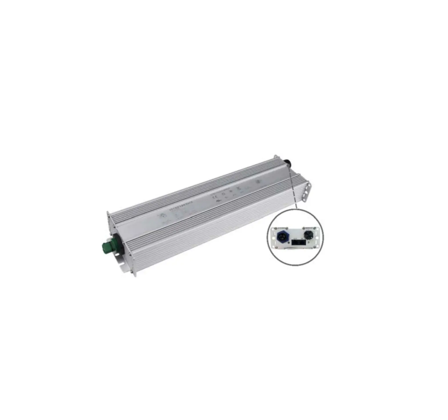
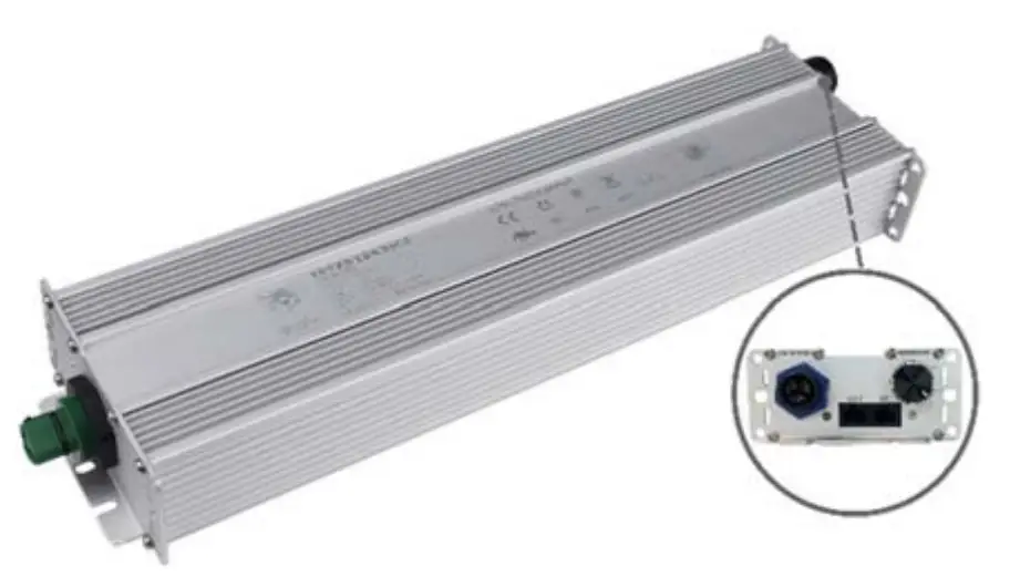
- Panel Mount Connectors Facilitates Installation
- Rotary Switch+RJ12 Connector
- Hot-plugging Protection
- Parallel LED Protection
- Ultra High Efficiency (Up to 95%)
- Full Power at Wide Output Current Range (Constant Power)
- Adjustable Output Current (AOC) with Programmability
- Isolated 0-10V/PWM/Resistor/3-Timer-Modes Dimmable
- INV Digital Dimming, UART Based Communication Protocol
- Dim-to-Off
- Minimum Dimming Level with 5% or 10% Selectable
- Maximum Dimming Level with 9V or 10V Selectable
- Fade Time Adjustable
- Low Inrush Current
- Output Lumen Compensation
- End-of-Life Indicator
- Input Surge Protection: DM 6kV, CM 10kV
- All-Around Protection: IOVP, IUVP, OVP, SCP, OTP
- IP66 and UL Dry/Damp/Wet Location
- 5 Years Warranty
Description
The SSM-760SxxxMGR series is a 760W, constant-current, programmable and IP66 rated LED driver that operates from 249-528Vac input with excellent power factor. Created for many lighting applications including high mast, sports, UV-LED, aquaculture and horticulture, etc. It provides rotary switch, RJ12 connector and dim-to-off functionality. The dimming control supports 0-10V dimming as well as two-way communication via Digital Dimming, a UART based communication protocol. The high efficiency of these drivers and compact metal case enables them to run cooler, significantly improving reliability and extending product life. To ensure trouble-free operation, protection is provided against input surge, input under voltage, input over voltage, output over voltage, short circuit, and over temperature.
Models
| Adjustable Output Current Range | Full-Power Current Range(1) | Default Output Current | Input Voltage Range(2) | Output Voltage Range | Max. Output Power | Typical Efficiency (3) | Typical Power Factor | Model Number | |
| 277Vac | 480Vac | ||||||||
| 1.4-15.8A | 14-15.8A | 14A | 249~528Vac 352~500Vdc | 34 ~ 54Vdc | 760W | 95.0% | 0.99 | 0.96 | SSM-760S15AMGR(4) |
Notes:
- Output current range with constant power at 760W.
- Certified voltage range: UL, FCC 277-480Vac; otherwise: 277-400Vac.
- Measured at 100% load and 480Vac input (see below “General Specifications” for details).
- SELV output.
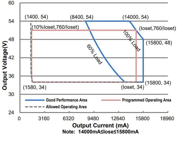
I-V Operating Area
Input Specifications
| Parameter | Min. | Typ. | Max. | Notes |
| Input AC Voltage | 249 Vac | – | 528 Vac | |
| Input DC Voltage | 352 Vdc | – | 500 Vdc | |
| Input Frequency | 47 Hz | – | 63 Hz | |
| Leakage Current | – | – | 0.75 MIU | UL 8750; 480Vac/ 60Hz |
| – | – | 0.70 mA | IEC 60598-1; 480Vac/ 60Hz | |
| Input AC Current | – | – | 3.24 A | Measured at 100% load and 277 Vac input. |
| – | – | 1.87 A | Measured at 100% load and 480 Vac input. | |
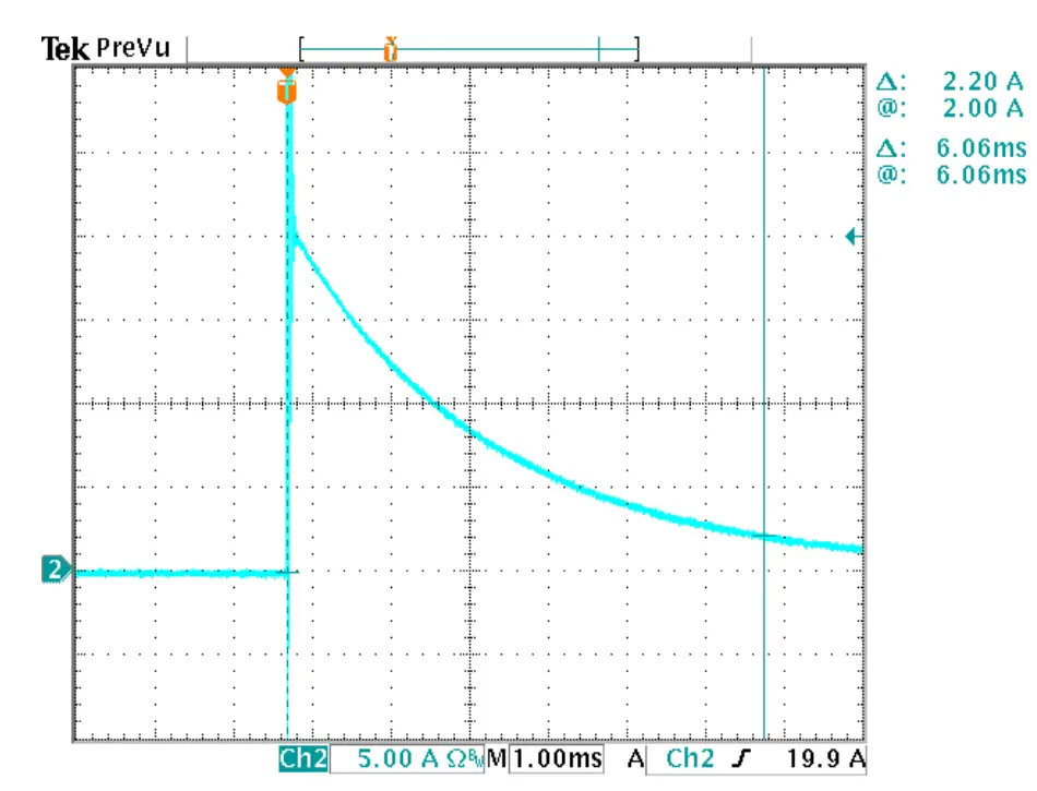
| Inrush Current(I2t) | – | – | 1.80 A2s | At 480Vac input, 25℃ cold start, duration=6.06 ms, 10%Ipk-10%Ipk. See Inrush Current Waveform for the details. |
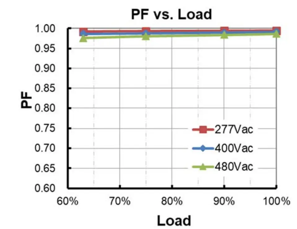
| PF | 0.90 | – | – | At 277-480Vac,50-60Hz, 60%-100%Load (456 – 760W) |
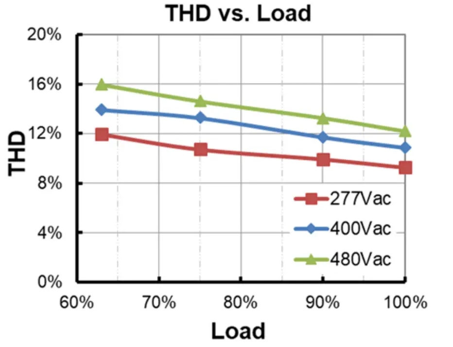
| THD | – | – | 20% |
Output Specifications
| Parameter | Min. | Typ. | Max. | Notes |
| Output Current Tolerance | -5%Ioset | – | 5%Ioset | 100% load |
| Output Current Setting(Ioset Range) SSM-760S15AMGR | 1400 mA | – | 15800 mA | |
| Output Current Setting Range with Constant Power SSM-760S15AMGR | 14000 mA | – | 15800 mA | |
| Total Output Current Ripple (pk-pk) | – | 5%Iomax | 10%Iomax | 100% load, 20 MHz BW |
| Output Current Ripple at < 200 Hz (pk-pk) | – | – | 2%Iomax | 70%-100% load |
| Startup Overshoot Current | – | – | 10%Iomax | 100% load |
| Parameter | Min. | Typ. | Max. | Notes |
| No Load Output Voltage SSM-760S15AMGR | – | – | 60 V | |
| Line Regulation | – | – | ±0.5% | 100% load |
| Load Regulation | – | – | ±3.0% | |
| Turn-on Delay Time | – | – | 0.5 s | Measured at 277-480Vac input, 60%- 100% Load |
| Temperature Coefficient of Ioset | – | 0.03%/°C | – | Case temperature = 0°C ~Tc max |
General Specifications
| Parameter | Min. | Typ. | Max. | Notes |
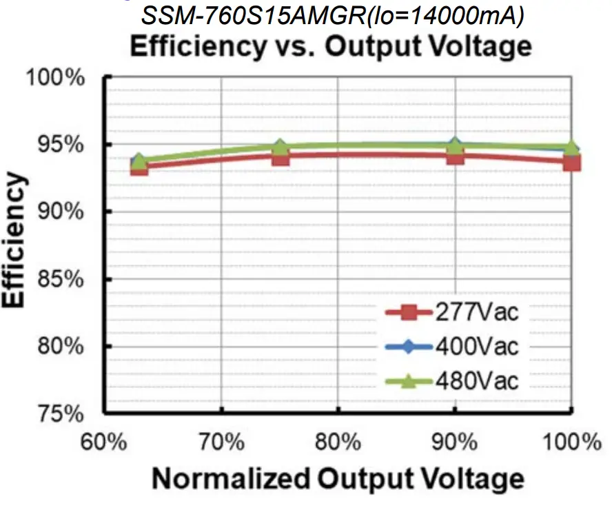
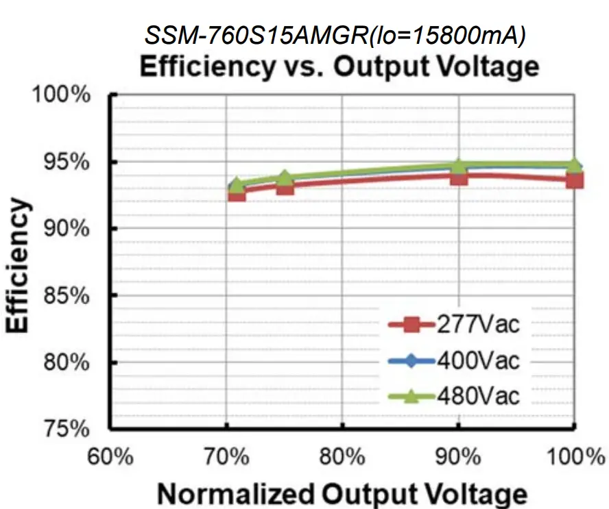
| Efficiency at 277 Vac input: SSM-760S15AMGR Io= 14000 mA Io= 15800 mA | 91.5% 91.5% | 93.5% 93.5% | – – | Measured at 100% load and steady-state temperature in 25°C ambient; (Efficiency will be about 2.0% lower if measured immediately after startup.) |
| Efficiency at 400 Vac input: SSM 760S15AMGR Io= 14000 mAIo= 15800 mA | 92.5% 92.5% | 94.5% 94.5% | – – | Measured at 100% load and steady-state temperature in 25°C ambient; (Efficiency will be about 2.0% lower if measured immediately after startup.) |
| Efficiency at 480 Vac input: SSM 760S15AMGR Io= 14000 mA Io= 15800 mA | 93.0% 93.0% | 95.0% 95.0% | – – | Measured at 100% load and steady-state temperature in 25°C ambient; (Efficiency will be about 2.0% lower if measured immediately after startup.) |
| Standby Power | – | 1.5 W | – | Measured at 480Vac/50Hz; Dimming off |
| MTBF | – | 224,000 Hour | – | Measured at 480Vac input, 80%Load and 25°C ambient temperature (MIL-HDBK- 217F) |
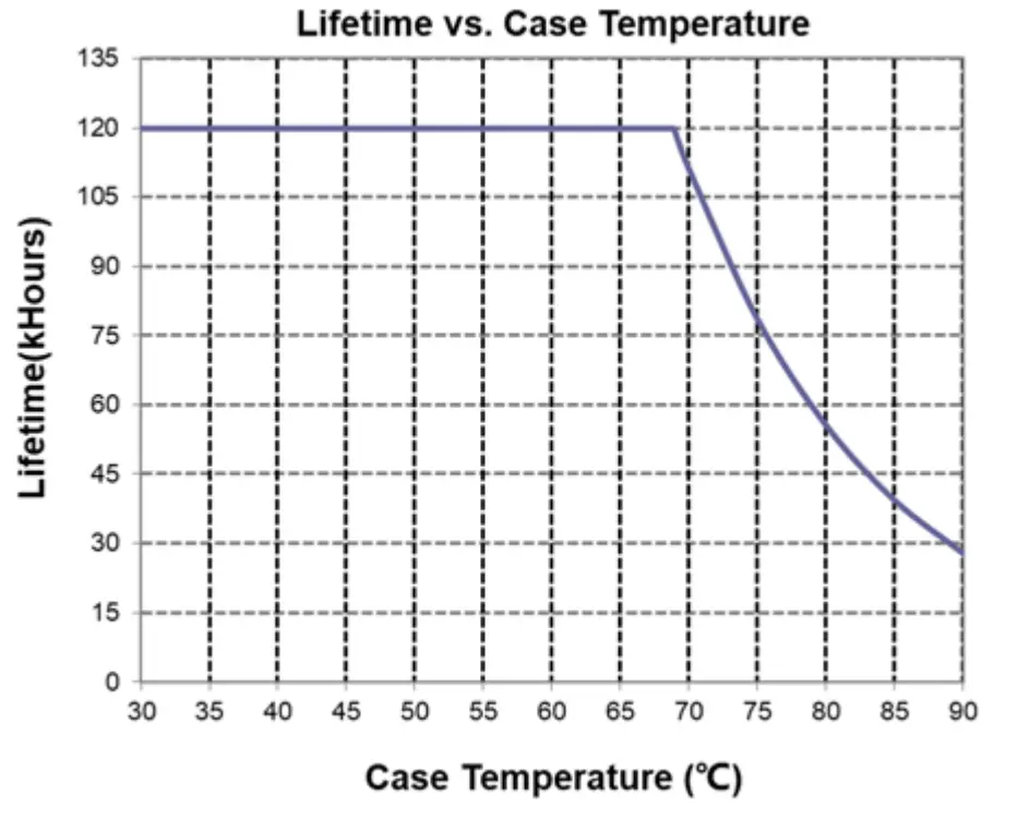
| Lifetime | – | 111,000 Hours | – | Measured at 480Vac input, 80%Load and 70°C case temperature; See lifetime vs. Tc curve for the details |
| – | 50,000 Hours | – | Measured at 277Vac input, 100%Load and 40°C ambient temperature | |
| Operating Case Temperature for Safety Tc_s | -40°C | – | +90°C | |
| Operating Case Temperature for Warranty Tc_w | -40°C | – | +80°C | Case temperature for 5 years warranty Humidity: 10%RH to 95%RH |
| Storage Temperature | -40°C | – | +85°C | Humidity: 5%RH to 95%RH |
| Dimensions Inches (L × W × H) Millimeters (L × W × H) | 15.35 × 4.25 × 1.91 390 × 108 × 48.5 | With mounting ear 16.34 × 4.25 × 1.91 415 × 108 × 48.5 | ||
| Net Weight | – | 3360 g | – | |
Dimming Specifications
| Parameter | Min. | Typ. | Max. | Notes |
| Absolute Maximum Voltage on the Vdim (+) Pin | -20 V | – | 20 V | |
| Source Current on Vdim (+)Pin | 90 uA | 100 uA | 110 uA | Vdim(+) = 0 V |
| Parameter | Min. | Typ. | Max. | Notes | |
| Dimming Output Range with 10%-100% (Default) | SSM-760S15AMGR | 10%Ioset | – | Ioset | 14000 mA ≤ Ioset ≤ 15800 mA |
| SSM-760S15AMGR | 1400 mA | – | Ioset | 1400 mA ≤ Ioset < 14000 mA | |
| Dimming Output Range with 5%-100% (Settable) | SSM-760S15AMGR | 5%Ioset | – | Ioset | 14000 mA ≤ Ioset ≤ 15800 mA |
| SSM-760S15AMGR | 700 mA | – | Ioset | 1400 mA ≤ Ioset < 14000 mA | |
| Recommended Dimming Input Range | 0 V | – | 10 V | Default 0-10V dimming mode. | |
| Dim off Voltage | 0.35 V | 0.5 V | 0.65 V | ||
| Dim on Voltage | 0.55 V | 0.7 V | 0.85 V | ||
| Hysteresis | – | 0.2 V | – | ||
| PWM_in High Level | 3 V | – | 10 V | Dimming mode set to PWM in Inventronics Programing Software. | |
| PWM_in Low Level | -0.3 V | – | 0.6 V | ||
| PWM_in Frequency Range | 200 Hz | – | 3 KHz | ||
| PWM_in Duty Cycle | 1% | – | 99% | ||
| PWM Dimming off (Positive Logic) | 3% | 5% | 8% | ||
| PWM Dimming on (Positive Logic) | 5% | 7% | 10% | ||
| PWM Dimming off ( Negative Logic) | 92% | 95% | 97% | ||
| PWM Dimming on ( Negative Logic) | 90% | 93% | 95% | ||
| Hysteresis | – | 2% | – | ||
Safety &EMC Compliance
| Safety Category | Standard |
| UL/CUL | UL 8750,CAN/CSA-C22.2 No. 250.13 |
| CE | EN 61347-1, EN 61347-2-13 |
| CB | IEC 61347-1, IEC 61347-2-13 |
| EMI Standards | Notes |
| EN 55015(1) | Conducted emission Test &Radiated emission Test |
| EN 61000-3-2 | Harmonic current emissions |
| EN 61000-3-3 | Voltage fluctuations & flicker |
| FCC Part 15(1) | ANSI C63.4 Class B |
| This device complies with Part 15 of the FCC Rules. Operation is subject to the following two conditions: [1] this device may not cause harmful interference, and [2] this device must accept any interference received, including interference that may cause undesired Operation. |
| EMS Standards | Notes |
| EN 61000-4-2 | Electrostatic Discharge (ESD): 8 kV air discharge, 4 kV contact discharge |
| EN 61000-4-3 | Radio-Frequency Electromagnetic Field Susceptibility Test-RS |
| EN 61000-4-4 | Electrical Fast Transient / Burst-EFT |
| EN 61000-4-5 | Surge Immunity Test: AC Power Line: Differential Mode 6 kV, Common Mode 10 kV |
| EN 61000-4-6 | Conducted Radio Frequency Disturbances Test-CS |
| EN 61000-4-8 | Power Frequency Magnetic Field Test |
| EN 61000-4-11 | Voltage Dips |
| EN 61547 | Electromagnetic Immunity Requirements Applies To Lighting Equipment |
Note: (1) This LED driver meets the EMI specifications above, but EMI performance of a luminaire that contains it depends also on the other devices connected to the driver and on the fixture itself
Lifetime vs. Case Temperature
Inrush Current Waveform
Efficiency vs. Load
Power Factor
Total Harmonic Distortion
Hot-plugging Protection
This feature protects LEDs when connecting to a driver that is already powered on. This is disabled by default and can be enabled through the Inventronics Programing Software.
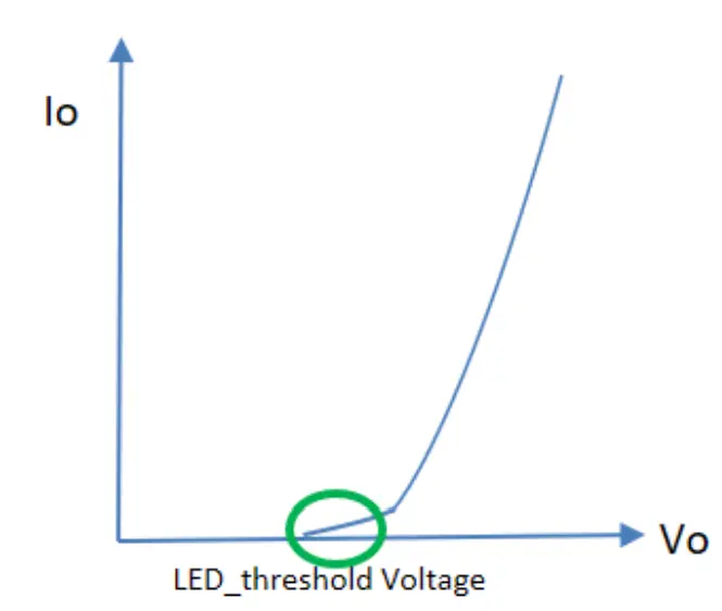
LED threshold voltage (Vth) is the minimum voltage required for current to flow through the LED load. After this threshold is met, the LED forward voltage (Vf) increases as the current increases. Set Vth close to, but higher than the actual LED threshold voltage for optimized performance. The greater the difference between the Vth setting and the actual LED threshold voltage, the higher the overshoot current will be. The Vth setting must be lower than Vf.
Please test, program, and tune this feature for each LED load design.
| Parameter | Min. | Typ. | Max. | Notes | |
| Hot-plugging Protection | LED Threshold Voltage Setting Range | 44 V | – | 54 V | Set Vth close to, but higher than the actual LED threshold voltage |
| Setting Tolerance | -2% | – | 2% | ||
Parallel LED Protection
This feature helps protect parallel LEDs from a high, overcurrent condition by limiting the voltage. This is disabled by default and can be enabled through the Inventronics Programing Software.
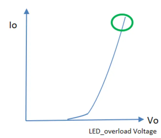
Set V_overload close to, but higher than the maximum forward voltage for optimized performance. The greater the difference between the V_overload setting and the maximum forward voltage, the higher the overload stress will be. The V_overload setting must be higher than Vf.
Please test, program, and tune this feature for each LED load design.
| Parameter | Min. | Typ. | Max. | Notes | |
| Parallel LED Protection | Overload Voltage Setting Range | 47 V | – | 56 V | Set V_overload close to, but higher than the maximum LED forward voltage |
| Setting Tolerance | -2% | – | 2% | ||
Protection Functions
| Parameter | Min. | Typ. | Max. | Notes | |
| Over Temperature Protection | Decreases output current, returning to normal after over temperature is removed. | ||||
| Short Circuit Protection | Auto Recovery. No damage will occur when any output is short circuited. The output shall return to normal when the fault condition is removed. | ||||
| Over Voltage Protection | Limits output voltage at no load and in case the normal voltage limit fails. | ||||
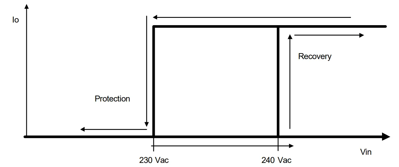
| Input Under Voltage Protection (IUVP) | Input Protection Voltage | 220 Vac | 230 Vac | 240 Vac | Turn off the output when the input voltage falls below protection voltage. |
| Input Recovery Voltage | 230 Vac | 240 Vac | 250 Vac | Auto Recovery. The driver will restart when the input voltage exceeds recovery voltage. | |
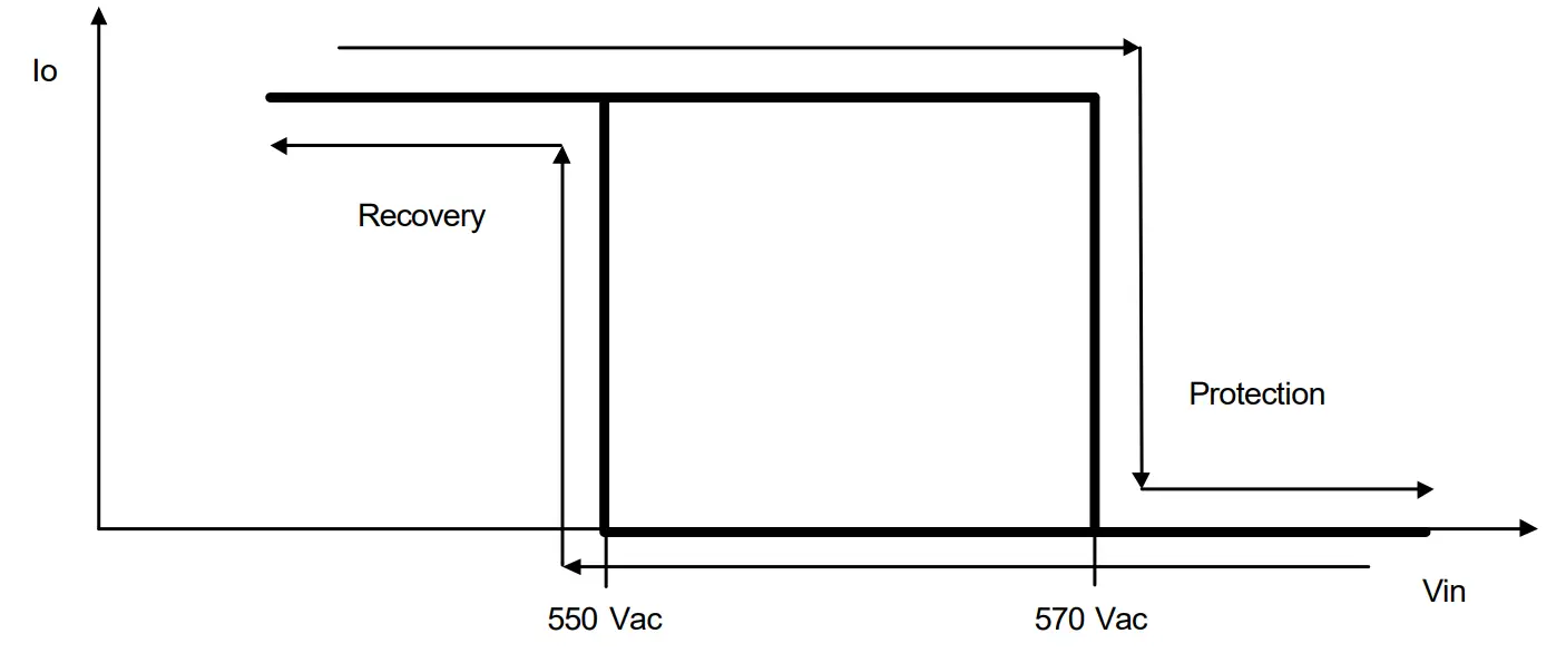
| Input Over Voltage Protection (IOVP) | Input Over Voltage Protection | 550 Vac | 570 Vac | 590 Vac | Turn off the output when the input voltage exceeds protection voltage. |
| Input Over Voltage Recovery | 530 Vac | 550 Vac | 570 Vac | Auto Recovery. The driver will restart when the input voltage falls below recovery voltage. | |
| Max. of Input Over Voltage | – | – | 590 Vac | The driver can survive for 8 hours with a stable input voltage stress of 590Vac. | |
Note: When removing the protective cap of RJ12, the waterproof protection performance should be evaluated together with external connected system by users.
Input Under Voltage Protection Diagram
Input Over Voltage Protection Diagram
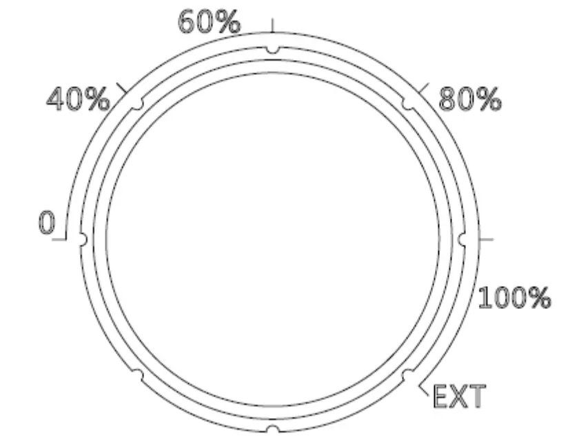
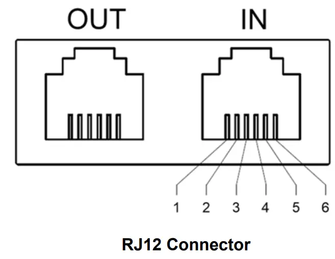
Rotary Switch and RJ12 Connector
Output current can be set as 0, 40%, 60%, 80%, 100% level by rotary switch and the output current can be dimmed by dimming wire in RJ12 connector when rotary switch is at ‘EXT’ position. The default mode is in ‘EXT’
| Pin | Function |
| 1,6 | Vprg |
| 2,5 | Dim+ |
| 3,4 | Dim- |
Dimming
0-10V Dimming
The recommended implementation of the dimming control is provided below
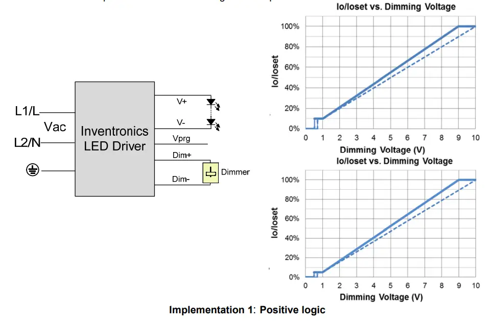
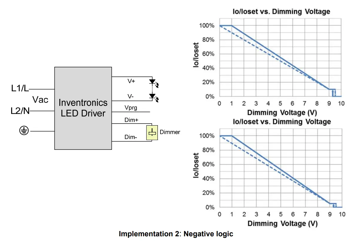
Notes:
- Do NOT connect Dim− to the output V− or V+, otherwise the driver will not work properly.
- The dimmer can also be replaced by an active 0-10V voltage source signal or passive components like zener.
- When 0-10V negative logic dimming mode and Dim+ is open, the driver will dim to off and be standby.
PWM Dimming
The recommended implementation of the dimming control is provided below.
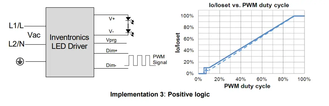
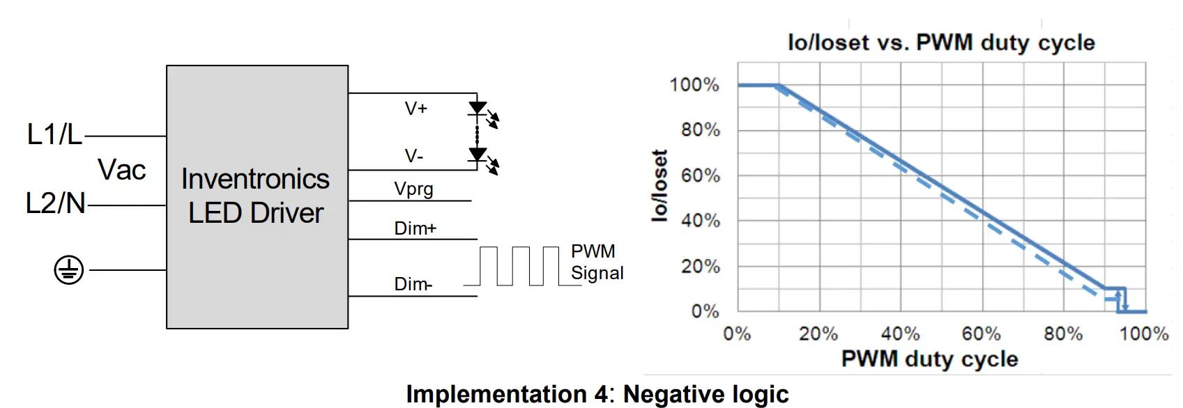
Notes:
- Do NOT connect Dim− to the output V− or V+, otherwise the driver will not work properly.
- When PWM negative logic dimming mode and Dim+ is open, the driver will dim to off and be standby.
Resistor Dimming
The recommended implementation of the dimming control is provided below.
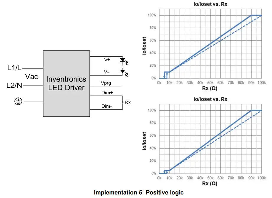
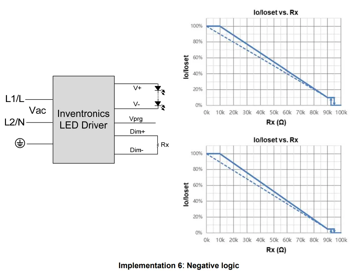
Notes:
- Do NOT connect Dim− to the output V− or V+, otherwise the driver will not work properly.
- When resistor negative logic dimming mode and Dim+ is open, the driver will dim to off and be standby.
Time Dimming
Time dimming control includes 3 kinds of modes, they are Self Adapting-Midnight, Self Adapting Percentage and Traditional Timer.
- Self Adapting-Midnight: Automatically adjusts the dimming curve based on the on-time of past two days (if difference <15 minutes), assuming that the center point of the dimming curve is midnight local time.
- Self Adapting-Percentage: Automatically adjusts the on-time of each step by a constant percentage = (actual on-time for the past 2 days if difference <15 min) / (programmed on-time from the dimming curve).
- Traditional Timer: Follows the programmed timing curve after power on with no changes.
Output Lumen Compensation
Output Lumen Compensation (OLC) may be used to maintain constant light output over the life of the LEDs by driving them at a reduced current when new, then gradually increasing the drive current over time to counteract LED lumen degradation.
Minimum Dimming Level with 5% or 10% Selectable
The minimum dimming level can be set as 5% or 10% by Inventronics Multi Programmer,10% is default.
Maximum Dimming Level with 9V or 10V Selectable
The maximum dimming level can be set as corresponding dimming voltage is 9V or 10V by Inventronics Multi Programmer,9V is default.
Fade Time Adjustable
Soft-start time and dimming slope can be adjusted by Inventronics Multi Programmer to get customized fade time experience, disable mode is default.
End Of Life
End-of-Life (EOL) is providing a visual notification to a user that the LED module has reached the end of manufacturer-specified life and that the replacement is recommended. Once active, an indication is given at each power-up of the driver, which the driver indicates this through a lower light output during the first 1 minute before normal operation is continued.
Digital Dimming
Inventronics Digital Dimming is a UART (Universal Asynchronous Receive Transmitter) based communication protocol. Please refer to Inventronics Digital Dimming file for details
Daisy Chain Application
Daisy chain system can support synchronous dimming of up to 100 drivers due to unique dimming interface design, please pay attention to right sequence of ‘IN’ and ‘OUT’ port for RJ12 connection。
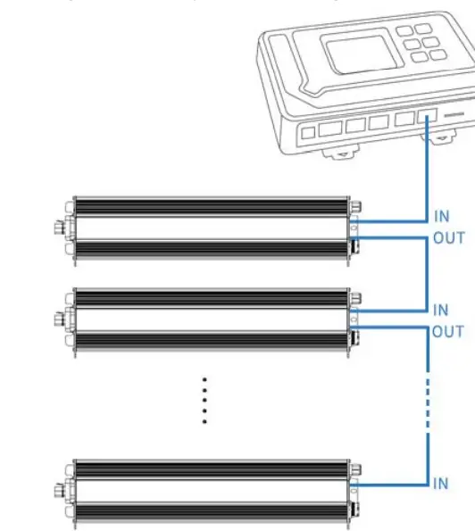
Daisy chain controlled by External Controller
Inventronics supports daisy chain connection for drivers that is dimmed by external controller. All drivers’ rotary switch need to be tuned to ‘EXT’.
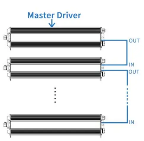
Daisy chain controlled by Driver-self
Inventronics offers the solution to use driver itself to control daisy chain dimming without the controller. The rotary switch of the master driver is tuned to required dimming level when the rest of drivers are tuned to ‘EXT’.
Programming Connection Diagram
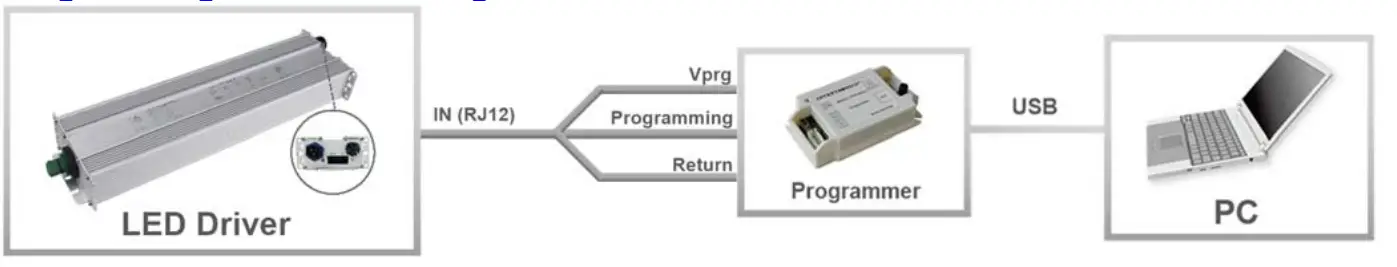
Note: The driver does not need to be powered on during the programming process.
- Please refer to PRG-MUL2 (Programmer) datasheet for details.
Mechanical Outline
INPUT(Panel Connector 3P Male)
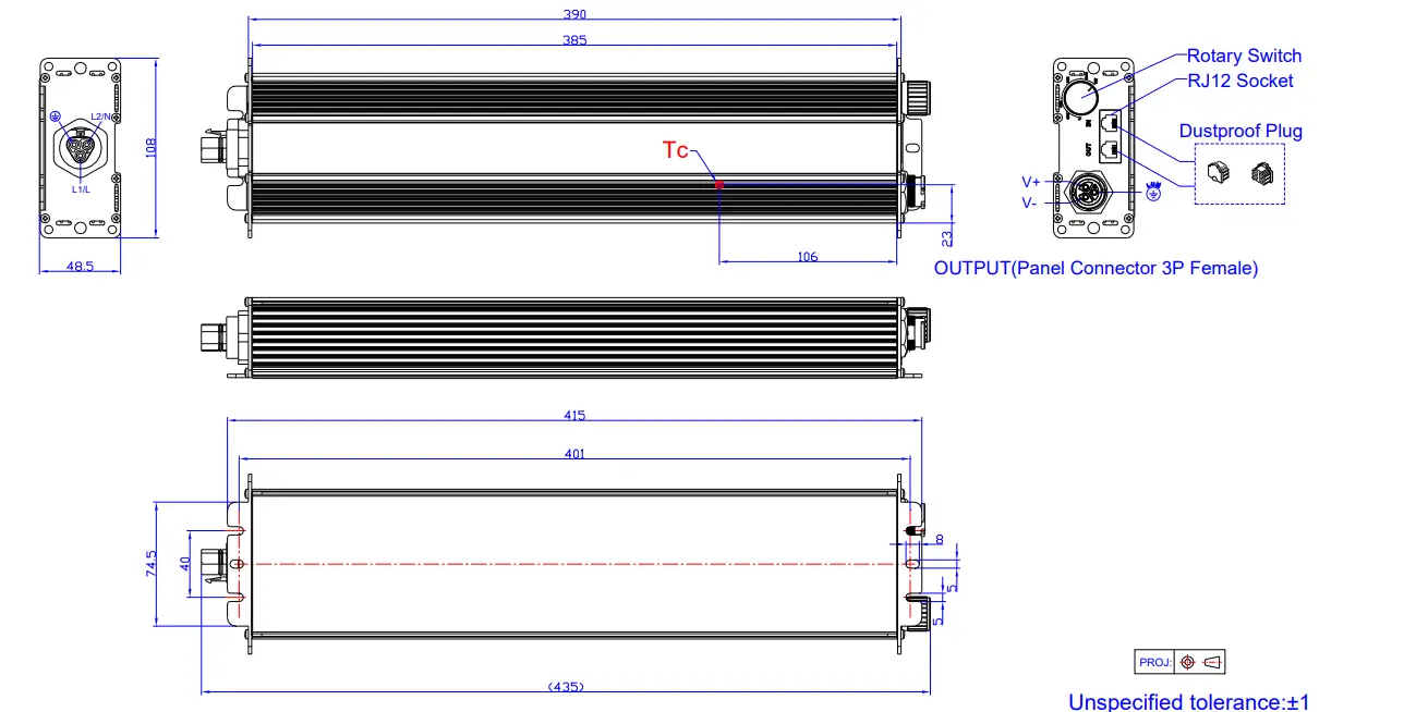
Note: This driver features UL Wet Location, IP66 panel mount connectors to streamline wiring in the field while still supporting stringent environmental conditions. The mating push-lock are not supplied by Inventronics. Please contact Wieland and Amphenol LTW or one of their suppliers for assistance sourcing the mating pushlock
| Location | Series | Rating voltage/current | PN of connector on driver | PN of mating push-lock |
| Vin | Wieland RST20i3 | 600V/10A | 96.032.1055.7 | 96.031.0055.7 (Spring) or 96.031.4055.7 (Screw) |
| Vo | ALTW X-Lok,C-Size | 300V/20A | ABAB-CAQ03000100 | CC-03BFMB-QL8APP |
RoHS Compliance
Our products comply with reference to RoHS Directive (EU) 2015/863 amending 2011/65/EU, calling for the elimination of lead and other hazardous substances from electronic products.
Revision History
| Change Date | Rev. | Description of Change | ||
| Item | From | To | ||
| 2023-02-10 | A | Datasheet Release | / | / |
Customer Support
www.inventronics-co.com
Tel: 86-571-56565800
Fax: 86-571-86601139
[email protected]