VisionTechShop XS300L Desktop POS Printer
Maintenance Attentions
Please read the following attentions carefully before operating the printer:
Safety warning
 Warning: the print head is a hot component. Do not touch the print head or the surrounding components during and after printing.
 Warning: do not touch the print head and connection plug-in to avoid damage of the print head due to static electricity.
Attentions
- In the process of troubleshooting, the steps described in the manual shall be strictly followed;
- It is strictly prohibited to plug and unplug the communication cable, replace the print head and maintain the printer when the printer and computer are still running
- In the process of handling the print head or other electronic components, pay attention to be equipped with anti-static measures;
- The time interval between the start-up and shutdown of the printer shall not be less than 20 seconds;
- The printer shall not print without paper, otherwise it will seriously damage the print rubber roller and the print head;
- Under the condition that the printing effect meets the requirements for use, it is suggested that users set the printing concentration at a low level as far as possible to improve the service life of the print head;
Printer features
Overview
This printer is a thermal note printer with automatic cutter. With high printing quality, high speed, high stability and other characteristics, it can be widely used in commercial POS system, catering industry and other occasions requiring on-site real-time printing of receipts. It can be connected to other equipment via serial, USB and Ethernet interfaces, while providing drivers for operating systems such as Windows XP/Windows 7/Windows 8/Windows 10/Linux, etc.
Main features
- Automatically cut papers.
- Low-noise and high-speed printing.
- It adopts the structure design to easily load papers.
- Built-in wall hanging function.
- Support for printing with marking paper and continuous paper.
- Support IP modification across network segments.
- Support cash-box control.
- Support retyping and queuing functions.
- Support over-temperature protection of print head and cutter anti-
- blocking functions.
- Support online upgrade of IAP.
- Support QR code printing in formats of QR Code and PDF417.
Technical parameters
| Model: | S300H |
| Color: | Black |
| Printing way: | Thermal sensitivity of direct row-type |
| Print speed: | 300mm/s |
| Paper roll width: | 80mm(79.5±0.5mm) |
| Paper roll: | Minimum inner diameter is Ф13mm, and maximum outer diameter is Ф83mm |
| Paper thickness: | 0.06-0.08mm |
| Print width: | 72±0.5mm |
| Paper delivery way: | Paper delivery from the upper position |
| Print density: | 576 points per row or 512 points per row |
| Line space: | 3.75mm (adjustable by command) |
| Print command: | Compatible with ESC/POS commands |
| Interface type: | 9P serial port +USB+ network port |
| Character size: | ANK character, Font A: 1.5mm×3.0mm (12×24 points) Font B: 1.1mm×2.1mm (9×17 points) Simplified/complex font: 3.0mm×3.0mm (24×24 points) |
| Figure: | Monochrome BMP and other image files can be downloaded to FLASH |
| Bar-code type: | UPC-A/UPC- E/JAN13(EAN13)/JAN8(EAN8)/CODE39/ITF/CODABAR/CODE93/CODE128 |
| QR code: | QR Code and PDF417 |
| Column number: | Font A – 42 columns or 48 columns/Font B – 56 columns or 64 columns / simplified and complex fonts – 21 columns or 24 columns |
| Extended character list: | PC437(Std.Europe), (Katakana), PC850(Multilingual), PC860(Portugal), PC863(Canadian), PC865(Nordic), (West Europe), (Greek), (Hebrew), (East Europe), (Iran), (WPC1252), PC866(Cyrillic#2), PC852(Latin2), (PC858) , (IranII), (Latvian), (Arabic) and (PT1511251) |
| Reliability: | The life of the engine is 150 kilometers and the life of the cutter is 1 million times |
| Paper cutting way: | Semi-cutting |
| Paper presence detection: | Support |
| Black label detection: | Support |
| Input buffer: | 2048Kbytes |
| NV Flash: | 256Kbytes |
| Adapter voltage input: | AC 100-240V/50~60Hz |
| Adapter voltage output: | DC 24V/2.5A |
| Cash-box control: | DC 24V/1A |
| Working environment: | Temperature: 0~45℃; humidity: 10~80% (non-condensate) |
| Storage environment: | Temperature: -10~60℃; humidity: 10~90% |
| Operating system: | Win 2000 /Win 2003 /Win XP /Win Vista/Win 7 /Win 8/ Win 10 /Linux |
| Boundary dimension: | 194.5*145*147mm (L*W*H) |
| Net weight: | 1.45kg |
Appearance and components
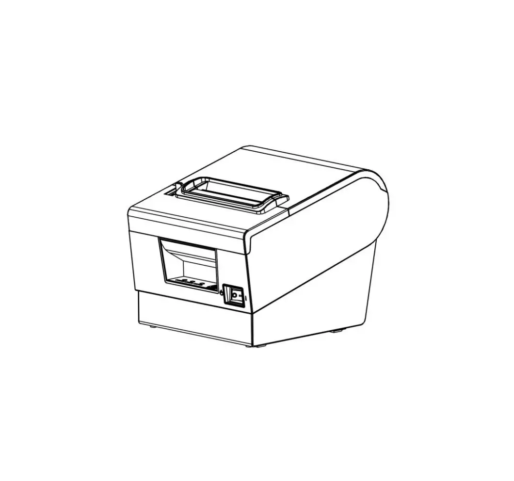
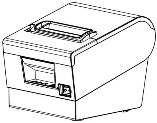
Product appearance
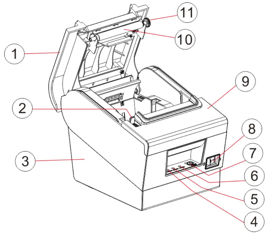
- Cover
- Open-cover push-button
- Base
- Power supply indicator lamp (POWER)
- Error indicator lamp (ERROR)
- Mispaper indicator (PAPER)
- Paper button (FEED)
- Power supply switch
- Front cover 1
- Rubber roller
- Rubber roller gear
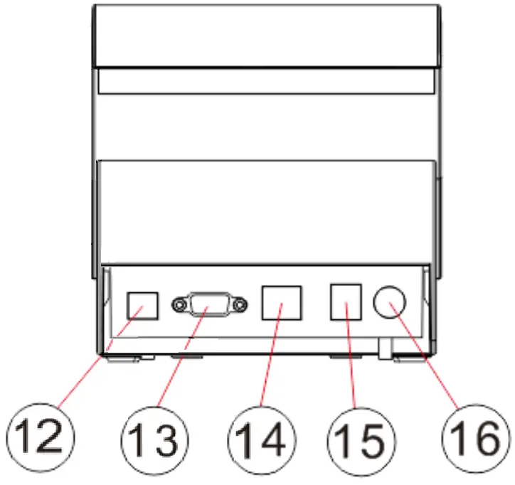
- USB interface
- Serial interface
- Ethernet interface
- Cash-box interface
- Power supply interface
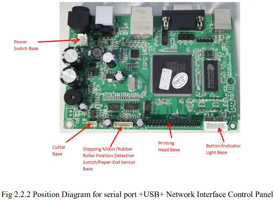
Connection diagram of control board components
The main control board, printing engine, cutter, keys, etc. are adopted for the printer to connect to the main control board through the connector or transfer board. The following is the connection diagram of the serial port +USB+ network port control board components: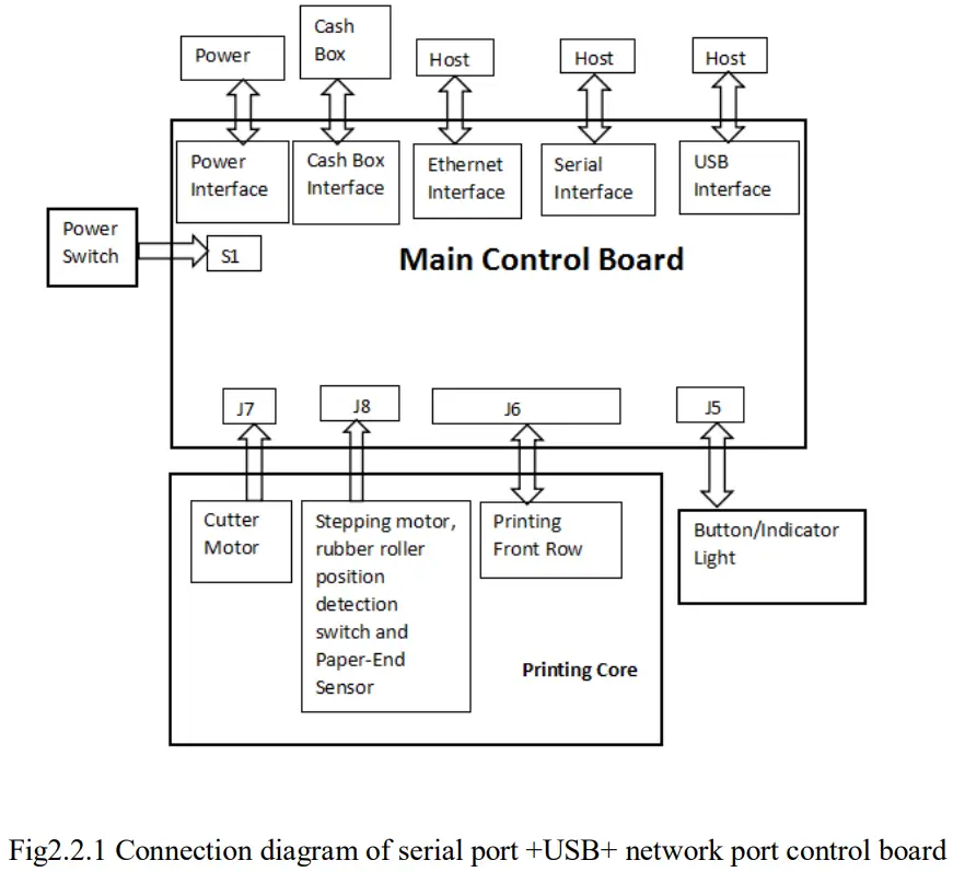
Printer interface
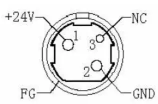
Power interfac
PIN | SIGNAL NAME |
1 | +24V |
2 | GND |
3 | N.C |
SHELL | F.G |
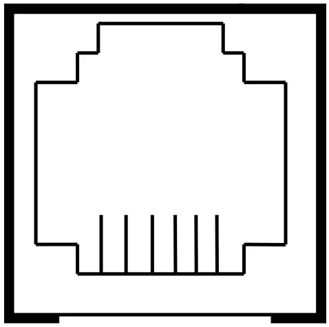
Cash-box interface
Cash-box control: 6-wire RJ-11 socket, output DC 24V/1A power signal to
drive the cash-box for action.
PIN | SIGNAL NAME |
1 | FGND |
2 | Drawer 1 |
3 | SW |
4 | CASH |
5 | Drawer 2 |
6 | GND |
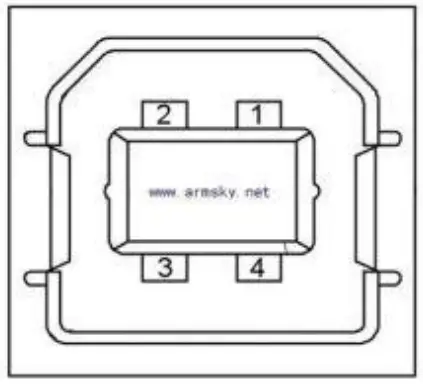
USB interface
PIN | SIGNAL NAME |
1 | VBUS |
2 | D- (DATA-) |
3 | D+ (DATA+) |
4 | GND |
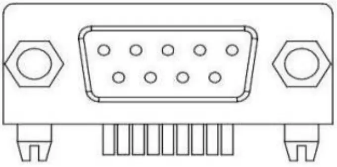
Serial interface
PIN | SIGNAL NAME |
1 | – |
2 | TXD |
3 | RXD |
4 | – |
5 | GND |
6 | DSR |
7 | – |
8 | CTS |
9 | – |
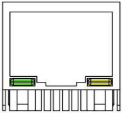
Ethernet interface
PIN | SIGNAL NAME |
1 | TD+ |
2 | TD- |
3 | RD+ |
4 | TXC |
5 | RCT |
6 | RD- |
7 | – |
8 | – |
9 | GREEN+ |
10 | GREEN – |
11 | YELLOW+ |
12 | YELLOW- |
Paper feed button(  )
)
Under the condition that the printer does not alarm, press this key to deliver paper, and press this key continuously to deliver paper continuously.
Power indicator light(  )
)
The color of the indicator light is blue. That the light is on indicates that the printer is powered on, while that the light is off indicates that the printer is powered off.
Error indicator light( )
)
The color of the indicator light is red. When the printer is out of paper, or there is something wrong with the cutter, or the print head is overheated, or there are other errors, the light flashes.
Paper shortage indicator light( )
)
The color of the indicator light is red. The light and the error light are on at the same time, indicating that the printer is short of paper. The light and the error light are off at the same time, indicating that the printer has
Description of printer state
- Error state
Including print head overheating, cover opening, lack of paper, cutter block and paper block, etc. - Standby state
Printer has no errors without printing or paper feed to wait for printing task. - Print state
The process from starting to print to the moment when the contents to be printed are printed after the print contents are received completely. - Paper delivery state
The process from paper delivery to paper cutting before the printing is completed.
Installation and use
Interface connection
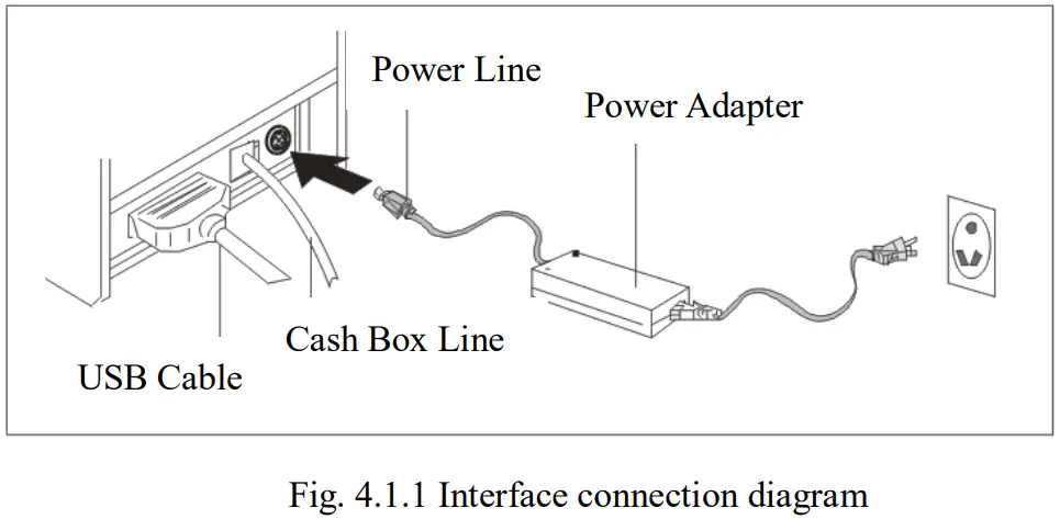
Note: the printer transmission interface in the picture will vary according to the type of machine you purchased. Please refer to the actual interface.
Connection to the power adapter
- Confirm that the power switch of the printer is off;
- Plug the power adapter cable plug facing straight up into the power interface at the back of the printer;
- Switch on the input power of the power adapter;
- Pay attention to the correct use of plugging and unplugging power adapter, otherwise it is easy to cause damage.
Attentions:
- Please use an exclusive power adapter or the matched product;
- When the plug of the power adapter is inserted and unplugged, the connector housing of the plug shall be held in hand to avoid pulling the cable forcibly;
- Dragging the power adapter cable shall be avoided, otherwise it will damage the cable and cause fire and electric shock;
- Placing power adapters around overheated equipment shall be avoided, otherwise the cable surface will melt, causing fire and electric shock;
- If you do not use the printer for a long time, please disconnect the power of printer power adapter.
Connection to the interface cable
- Confirm that the power switch of the printer is off;
- Insert the interface cable into the matched interface and fix it with screws (or snap spring) on the plug;
- Connect the other end of the interface cable to the host.
Connection to the cash-box
- Confirm that the power switch of the printer is off;
- Insert the cash-box connection cable into the cash-box interface at the back of the printer.
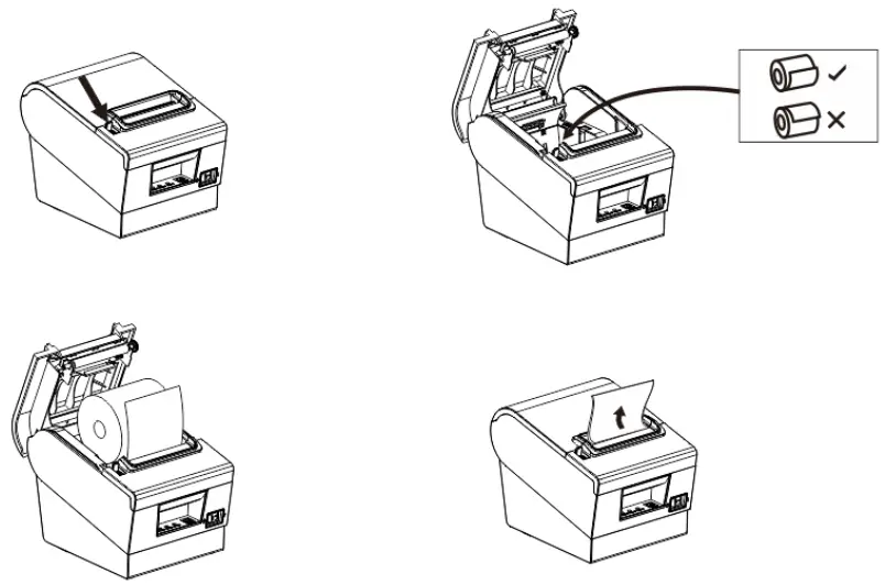
Paper roll installation
After the connection between the power adapter and the interface cable is completed, the medium can be installed for printing. Before printing, the paper specification used by the printer shall be confirmed. This printer only supports 80mm-wide thermal paper rolls.
- Turn off the power of the printer;
- Press the uncapping button to open the printer flap;
- Put the paper rolls into the printer and pay attention to the placement direction of the paper rolls;
- Close the printer flap.
Fault treatment guidelines
In case of printer failure, please refer to this chapter for corresponding treatment. If you still can’t fix the problem, please contact the agent or manufacturer.
Power
| Fault | Possible cause | Solution |
| The power indicator light is off | The AC/DC power adapter is not connected properly | Reconnect the power adapter |
| AC/DC power adapter is in fault | Replace the power adapter | |
| The power supply circuit of the main control board is out of order | Repair or replace the main control board | |
| Lamp board is in fault | Repair or replace the lamp board |
| Fault | Possible cause | Solution |
| The printer prints without paper | Printer paper is not installed correctly | Install the printing paper according to the instructions in the manual |
| The paper characteristics used is incorrect | Use thermal paper for printing | |
| Print head is damaged | Replace the print head | |
| The main board is damaged | Repair or replace the main control board | |
| The printer paper is installed incorrectly | Install the printing paper according to the instructions in the manual | |
| The print quality is poor or print product is blurred. | Paper quality is poor | Use high-quality paper rolls |
| The settings are incorrect | Increase print concentration | |
| The print head is damaged | Replace the print head | |
| The printer prints with dirty spots | The paper is stained with dirt, or the paper quality is poor | Check or replace the printer paper |
| The print head is dirty | Clean the print head with alcohol |
Paper feed
| Fault | Possible cause | Solution |
| There is no paper feed or paper feed is abnormal | Paper is blocked in the printer | Clear the blocked paper and install the printing paper according to the operation instructions |
| Gear is damaged | Replace the gear | |
| The main board is damaged | Repair or replace the main control board | |
| Print head motor is in fault | Replace the print head | |
| There is foreign matter in the gear | Clean the gear |
Cash-box
| Fault | Possible cause | Solution |
| The cash-box cannot be opened | The cash-box cable does not match | Replace with cables of corresponding specification |
| Cash-box drive cable is damaged | Replace the cable | |
| Cash-box drive circuit is damaged | Repair or replace the main control board | |
| The cash-box cannot be closed | Cash-box drive circuit is damaged | Repair or replace the main control board |
Indicator light/buzzer
| Fault | Possible cause | Solution |
| The key or indicator is not working | Key indicator light cable is not reliably connected | Reconnect the cable |
| Cable or connector is damaged | Replace cables or connectors | |
| The key or indicator light is damaged | Replace keys or indicator lights | |
| State show that the circuit is damaged | Replace or repair the main control board | |
| The buzzer is not working | The buzzer is damaged | Replace the buzzer |
| The buzzer control circuit is abnormal | Replace or repair the main control board | |
| The settings are incorrect | Set according to requirements of the manual |
Communication
| Fault | Possible cause | Solution |
| The printer is in normal condition but does not print | The communication cable is not reliably connected to the printer | Reconnect the communication cable |
| The communication cables used do not match | Use a communication cable that matches the printer | |
| Communication cable or connector is damaged | Replace communication cables or connectors | |
| Communication interface board is damaged | Replace the communication interface board | |
| Extension interface circuit of main control board is in fault | Repair or replace the main control board |
Paper cutting
| Fault | Possible cause | Solution |
|
Cutter is blocked | The blade is deformed | Change the cutter |
| Motor is burnt out | Change the cutter | |
| Paper scrap is accumulated | Clean up the scraps of paper on each transmission component | |
|
Paper is blocked | Head piece is overheated | Reduce the heating power of the drive head piece |
| The paper feed position is wrong | Place the paper parallel to the side of the paper slot between the rubber roller and TPH | |
| Continuous paper cutting | The blade is worn or damaged | Change the cutter |
| The paper is too thick | Change for standard paper |
Dis-assembly and assembly of main components
Attentions during operation:
- When the printer is working normally, do not remove any components of the printer or loosen any screws of the printer;
- When you are disassembling and assembling components, please carefully check whether the connecting wires are damaged;
- When you are handling the printer engine and electronic components, pay attention to take anti-static measures;
- During the dis-assembly and assembly process, do not let screws or other components into the printer;
- Pay attention to avoid damage to the printer engine during assembly and dis-assembly. Maintenance tools: cross screwdriver, cutting pliers.
Auxiliary materials: grease, alcohol, absorbent cotton ball.
Printer dis-assembly
Remove the printer base
| Explanatory chart | Diagram |
| Printer appearance figure |
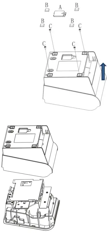 | A. Remove the battery cover first. B. Then remove the 4 “T” shaped foot pads. C. Use a Phillips screwdriver to remove the 4 H3*6mm screws fixing the base. Then remove the base in the same direction. |
Remove the printer main board, light board and middle frame iron plate
| Explanatory chart | Diagram |
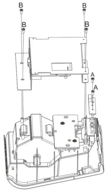 | A. Use a Phillips screwdriver to remove the 2 PA3*8mm screws that fix the light board, and then remove the light board. B Use a Phillips screwdriver to remove the 4 PA3*8mm screws securing the middle frame iron plate, and then remove the middle frame iron plate. |
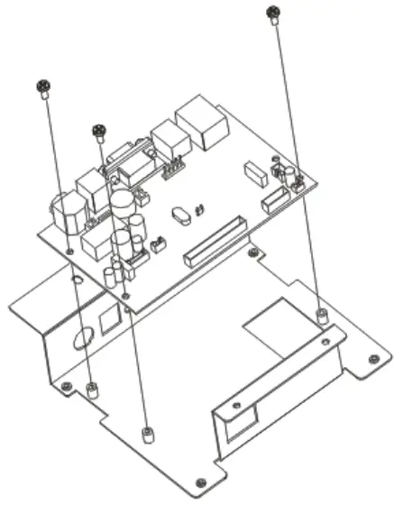 | Use a Phillips screwdriver to remove the 3 H3*6mm screws securing the motherboard, and then remove the motherboard. |
Remove the printer weight and power switch
| Explanatory chart | Diagram |
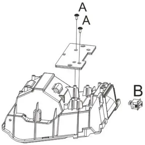
| A. Remove the two PWA3 * 10mm screws with the cross screwdriver, and then remove the weighted insert. B. Remove the power supply switch. |
Removing the front cover and flip cover of the printer
| Explanatory chart | Diagram |
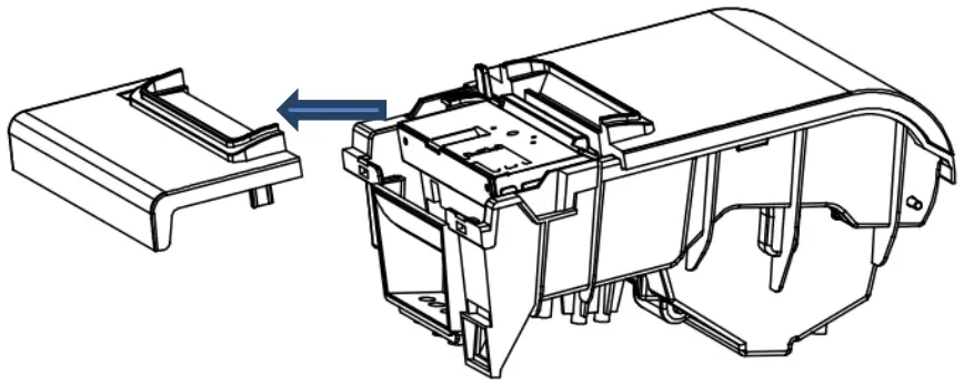 | Remove the front cover in the direction. |
 | A. First take out the fixed shaft from the side. B. Take out the flip cover upwards. C. Remove the left/right torsion spring from the flip bracket. |
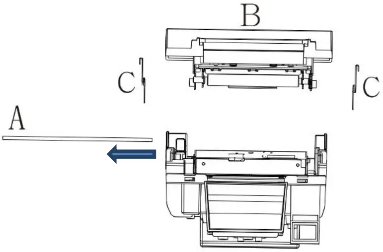
Removing the Printer Clamshell Bracket and Rubber Roller Assembly
| Explanatory chart | Diagram |
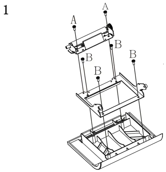 | A. Use a Phillips screwdriver to remove the 2 H3*6mm screws that fix the rubber roller assembly, and then remove the rubber roller assembly. B. Use a Phillips screwdriver to remove the 4 PA3*8mm screws that fix the flip bracket, and then remove the flip bracket. |
Disassemble the printer movement
| Explanatory chart | Diagram |
| First remove the 4 TB3*10mm screws that fix the movement with a Phillips screwdriver, then remove the movement; then remove the cover opening button. |
Printer assembly
When you are assembling, simply assemble in the reverse order of dis-assembly.
Cleaning the printer
Dust, foreign matter, stickum or other contaminants that stick to inside print head or printer may degrade the print quality. At the time of decontamination, please clean the print head according to the following methods.
Cleaning the print head
- Please open the cover of the printer and clean with a cleaning pen or cotton swab stained with diluted alcohol (alcohol or isopropanol) from the center of the print head to the sides.
- After cleaning the print head, do not use the printer immediately, wait for the clean alcohol used to evaporate completely (1 to 2 minutes), and the print head must be completely dry before use.
Cleaning sensor, rubber roller and paper paths
- Please open the flap of the printer and take out the paper roll.
- Use dry cotton cloth or cotton swab to remove dust or foreign matters.
- Soak cotton cloth or cotton swab with medical alcohol and wipe away sticky foreign matters or other contaminants with it.
- Do not use the printer immediately after cleaning components, wait for the alcohol to evaporate completely (1 to 2 minutes), and use the printer after it is completely dry.
※ Clean components when print quality or paper detection performance degrades.
![]() Attention
Attention
- Be sure to turn off the power of the printer before cleaning.
- When the printer is printing, the print head will become very hot; therefore, if you want to clean the print head, turn off the printer power and wait 2 to 3 minutes before starting.
- When you are cleaning the print head, pay attention not to touch the heated component of the print head to avoid its damage caused by static electricity, etc.
- Be careful not to scratch or damage the print head.
- Forceps and other metal tools shall not be used to scratch the surface of print head, rubber roller and sensor.
- Organic solvents such as gasoline, acetone, etc. shall not be used
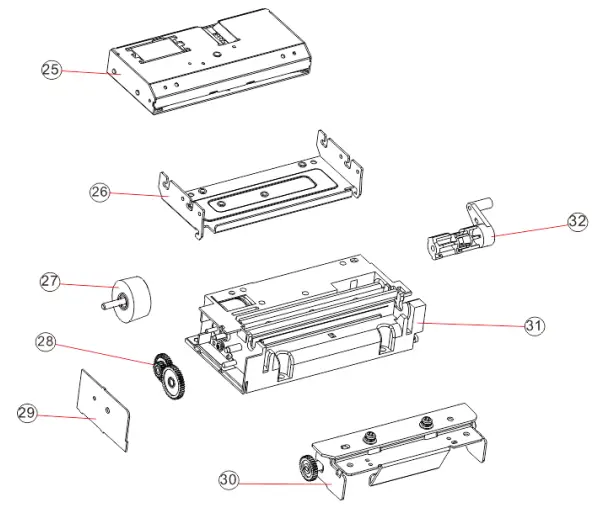
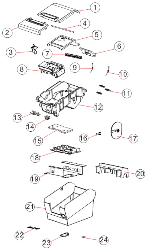
Appendix: printer explosion diagram
List of printer components
| No. | Material name |
| 1 | Front cover |
| 2 | The front cover |
| 3 | open button |
| 4 | fixed shaft |
| 5 | flip stand |
| 6 | baffle |
| 7 | long roller |
| 8 | printing core |
| 9 | left torsion spring |
| 10 | right torsion spring |
| 11 | short roller |
| 12 | middle frame |
| 13 | Light board |
| 14 | switch |
| 15 | weighted tablets |
| 16 | telescopic board |
| 17 | Roller adjustment plate |
| 18 | motherboard |
| 19 | Middle frame iron plate |
| 20 | hidden wire slot |
| 21 | base |
| 22 | The key label |
| 23 | battery cover |
| 24 | T-shaped feet |
| 25 | Cutter |
| 26 | Cutter holder |
| 27 | Stepping motor |
| 28 | Speed-reduction gear set |
| 29 | Side cover |
| 30 | Rubber roller components |
| 31 | Print head body |
| 32 | Remote lever |
Explosion diagram of the whole printer
Decomposition diagram of printer engine