Losi LOS03015 Night Crawler SE 4WD Rock Crawler Brushed RTR Instruction Manual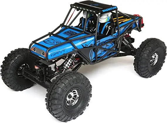
NOTICE
All instructions, warranties and other collateral documents are subject to change at the sole discretion of Horizon Hobby, LLC.
For up-to-date product literature, visit horizonhobby.com and click on the support tab for this product.
MEANING OF SPECIAL LANGUAGE
The following terms are used throughout the product literature to indicate various levels of potential harm when operating this product:
WARNING: Procedures, which if not properly followed, create the probability of property damage, collateral damage, and serious injury OR create a high probability of superficial injury.
CAUTION: Procedures, which if not properly followed, create the probability of physical property damage AND a possibility of serious injury.
NOTICE: Procedures, which if not properly followed, create a possibility of physical property damage AND a little or no possibility of injury.
![]() WARNING: Read the ENTIRE instruction manual to become familiar with the features of the product before operating. Failure to operate the product correctly can result in damage to the product, personal property and cause serious injury.
WARNING: Read the ENTIRE instruction manual to become familiar with the features of the product before operating. Failure to operate the product correctly can result in damage to the product, personal property and cause serious injury.
This is a sophisticated hobby product. It must be operated with caution and common sense and requires some basic mechanical ability. Failure to operate this Product in a safe and responsible manner could result in injury or damage to the product or other property. This product is not intended for use by children without direct adult supervision. Do not use with incompatible components or alter this product in any way outside of the instructions provided by Horizon Hobby, LLC. This manual contains instructions for safety, operation and maintenance. It is essential to read and follow all the instructions and warnings in the manual, prior to assembly, setup or use, in order to operate correctly and avoid damage or serious injury.
![]() WARNING AGAINST COUNTERFEIT PRODUCTS Always purchase from a Horizon Hobby, LLC authorized dealer to ensure authentic high-quality Spektrum product. Horizon Hobby, LLC disclaims all support and warranty with regards, but not limited to, compatibility and performance of counterfeit products or products claiming compatibility with DSM or Spektrum technology
WARNING AGAINST COUNTERFEIT PRODUCTS Always purchase from a Horizon Hobby, LLC authorized dealer to ensure authentic high-quality Spektrum product. Horizon Hobby, LLC disclaims all support and warranty with regards, but not limited to, compatibility and performance of counterfeit products or products claiming compatibility with DSM or Spektrum technology
Age Recommendation: Not for children under 14 years. This is not a toy.
SAFETY PRECAUTIONS AND WARNINGS
As the user of this product, you are solely responsible for operating in a manner that does not endanger yourself and others or result in damage to the product or property of others.
This model is controlled by a radio signal subject to interference from many sources outside your control. This interference can cause momentary loss of control, so it is advisable to always keep a safe distance in all directions around your model as this margin will help avoid collisions or injury.
- Never operate your model with low transmitter batteries.
- Always operate your model in open spaces away from full-size vehicles, traffic and people.
- Never operate the model in the street or in populated areas for any reason.
- Carefully follow the directions and warnings for this and any optional support equipment (chargers, rechargeable battery packs, etc.) you use.
- Keep all chemicals, small parts and anything electrical out of the reach of children.
- Never lick or place any portion of the model in your mouth as it could cause serious injury or even death.
- Exercise caution when using tools and sharp instruments.
- Take care during maintenance as some parts may have sharp edges.
- Immediately after using your model, do NOT touch equipment such as the motor, electronic speed control and battery, because they generate high temperatures. You may burn yourself seriously touching them.
- Do not put fingers or any objects inside rotating and moving parts, as this may cause damage or serious injury.
- Always turn on your transmitter before you turn on the receiver in the car. Always turn off the receiver before turning your transmitter off.
- Keep the wheels of the model off the ground when checking the operation of the radio equipment.
BOX CONTENTS
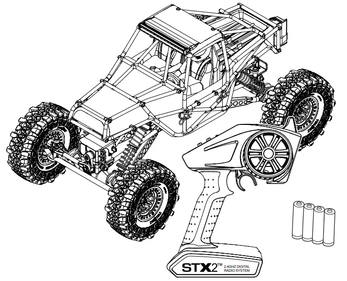
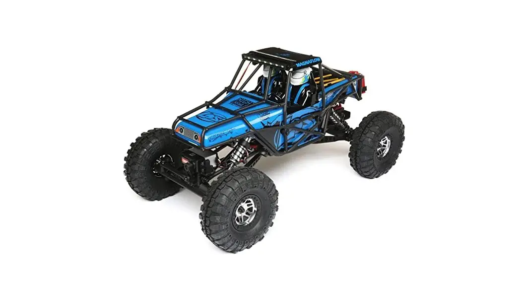
- Losi® Night Crawler SE RTR: 1/10-Scale 4WD Rock Crawler
- Spektrum™ STX2® 2CH 2.4GHz FHSS Transmitter (SPMSTX200)
- Spektrum™ STX2® 2CH 2.4GHz FHSS Receiver (SPMSRX200)
- Spektrum™9KG 23T Waterproof Servo (SPMS605)
- Dynamite® 60A FWD/REV Brushed ESC (DYNS2210)
- Dynamite® 35T 540 Brushed Motor (DYNS1216)
- 4 AA batteries (for transmitter)
WATER-RESISTANT VEHICLE WITH WATERPROOF ELECTRONICS
Your new Horizon Hobby vehicle has been designed and built with a combination of waterproof and water-resistant components to allow you to operate the product in many “wet conditions,” including puddles, creeks, wet grass, snow and even rain.
While the entire vehicle is highly water-resistant, it is not completely waterproof and your vehicle should NOT be treated like a submarine. The various electronic components used in the vehicle, such as the Electronic Speed Control (ESC), servo(s) and receiver are waterproof, however, most of the mechanical components are water-resistant and should not be submerged.
Metal parts, including the bearings, hinge pins, screws and nuts, as well as the contacts in the electrical cables, will be susceptible to corrosion if additional maintenance is not performed after running in wet conditions. To maximize the long-term performance of your vehicle and to keep the warranty intact, the procedures described in the “Wet Conditions Maintenance” section below must be performed regularly if you choose to run in wet conditions. If you are not willing to perform the additional care and maintenance required, then you should not operate the vehicle in those conditions.
![]() CAUTION: Failure to exercise caution while using this product and complying with the following precautions could result in product malfunction and/or void the warranty.
CAUTION: Failure to exercise caution while using this product and complying with the following precautions could result in product malfunction and/or void the warranty.
GENERAL PRECAUTIONS
- Read through the wet conditions maintenance procedures and make sure that you have all the tools you will need to properly maintain your vehicle.
- Not all batteries can be used in wet conditions. Consult the battery manufacturer before use. Caution should be taken when using Li-Po batteries in wet conditions.
- Most transmitters are not water-resistant. Consult your transmitter’s manual or the manufacturer before operation.
- Never operate your transmitter or vehicle where lightning may be present.
- Do not operate your vehicle where it could come in contact with salt water (ocean water or water on salt-covered roads), contaminated or polluted water. Salt water is very conductive and highly corrosive, so use caution.
- Even minimal water contact can reduce the life of your motor if it has not been certified as water-resistant or waterproof. If the motor becomes excessively wet, apply very light throttle until the water is mostly removed from the motor. Running a wet motor at high speeds may rapidly damage the motor.
- Driving in wet conditions can reduce the life of the motor. The additional resistance of operating in water causes excess strain. Alter the gear ratio by using a smaller pinion or larger spur gear. This will increase torque (and motor life) when running in mud, deeper puddles, or any wet conditions that will increase the load on the motor for an extended period of time.
WET CONDITIONS MAINTENANCE
- Drain any water that has collected in the tires by spinning them at high speed. With the body removed, place the vehicle upside down and pull full throttle for a few short bursts until the water has been removed.
![]() CAUTION: Always keep hands, fingers, tools and any loose or hanging objects away from rotating parts when performing the above drying technique.
CAUTION: Always keep hands, fingers, tools and any loose or hanging objects away from rotating parts when performing the above drying technique.
- Remove the battery pack(s) and dry the contacts. If you have an air compressor or a can of compressed air, blow out any water that may be inside the recessed connector housing.
- Remove the tires/wheels from the vehicle and gently rinse the mud and dirt off with a garden hose. Avoid rinsing the bearings and transmission.
![]() NOTICE: Never use a pressure washer to clean your vehicle.
NOTICE: Never use a pressure washer to clean your vehicle.
- Use an air compressor or a can of compressed air to dry the vehicle and help remove any water that may have gotten into small crevices or corners.
- Spray the bearings, drive train, fasteners and other metal parts with a water displacing light oil. Do not spray the motor.
- Let the vehicle air dry before you store it. Water (and oil) may continue to drip for a few hours.
- Increase the frequency of disassembly, inspection and lubrication of the following:
- Front and rear axle hub assembly bearings.
- All transmission cases, gears and differentials.
- Motor—clean with an aerosol motor cleaner and re-oil the bushings with lightweight motor oil.
QUICK START
Please read the entire manual to gain a full understanding of the vehicle, fine tuning the setup and performing maintenance.
- Read the safety precautions found in this manual.
- Charge a battery for the vehicle. Refer to the included charging warnings and instructions for battery charging information.
- Install the AA batteries in the transmitter. Only use alkaline or rechargeable batteries.
- Install the fully charged battery in the vehicle.
- Power ON the transmitter and then the vehicle. Wait 5 seconds for the ESC to initialize. Always power the transmitter ON before the vehicle and power it OFF after the vehicle has been powered OFF.
- Check the steering and throttle control directions. Verify that the servos are moving in the correct direction.
- Drive your vehicle.
- Perform any necessary maintenance.
CHARGING THE BATTERY
Choose a battery designed to work with the Dynamite® Prophet™ Sport 50W AC/DC Charger (DYNC2010CA) or the Dynamite® Prophet™ Sport LiPo 35W AC Charger (DYNC20005CA). We recommend the Dynamite® Speedpack® 7.2V 3300 mAh NiMH 6C Flat with EC3™ connector (DYN1070EC) or the Dynamite® Reaction® 7.4V 5000mAh2S 20C LiPo hardcase with EC3 connector (DYN9004EC)
INSTALLING THE BATTERY
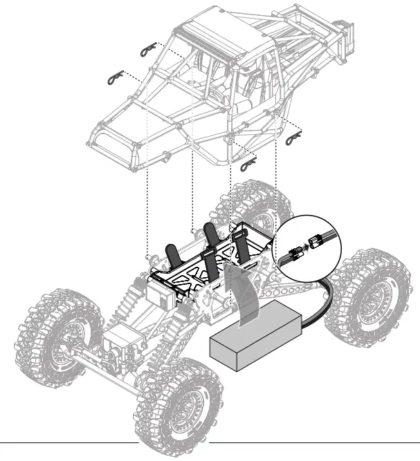
- Ensure the ESC is powered OFF.
- Remove the vehicle body.
- Connect the battery to the ESC noting the correct polarity.
- Install the fully charged battery in the vehicle.
- Secure the battery to the battery tray with hook and loop straps.
- Power ON the transmitter, then the vehicle.
TRANSMITTER CONTROLS
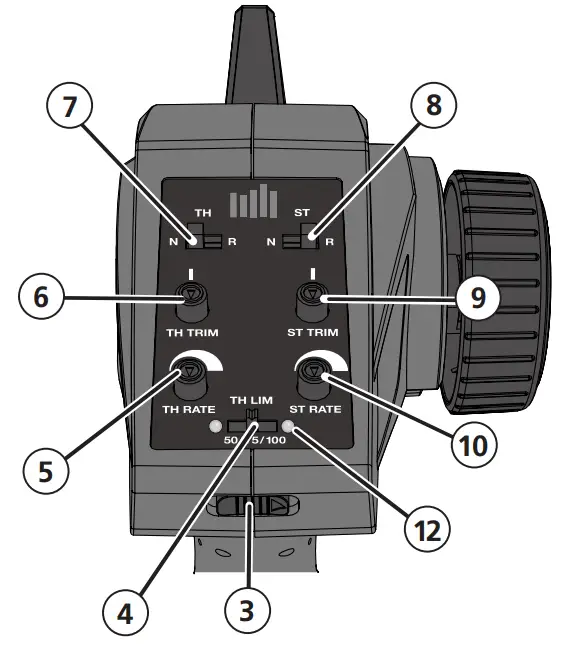
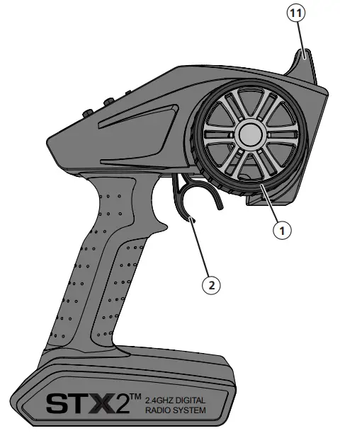
- Steering Wheel Controls direction (left/right) of the model
- Throttle Trigger Controls speed and direction (forward/brake/reverse) of the model
- ON/OFF Switch Turns the power ON/OFF
- Throttle Limiting Switch Adjusts the throttle limit from 50%, 75%, and 100%
- TH Rate Adjusts the end point of the throttle
- TH Trim Adjusts the throttle neutral point
- TH REV Reverses the function of the speed control when pulled back or pushed forward
- ST REV Reverses the function of the steering when the wheel is turned left or right
- ST Trim Adjusts the steering center point
- ST Rate Adjusts the end point of the steering
- Antenna Transmits the signal to the model
- Indicator Lights
- Solid red lights—Indicates radio connectivity and adequate battery power
- Flashing red lights—Indicates the battery voltage is critically low. Replace batteries
INSTALLING THE TRANSMITTER BATTERIES 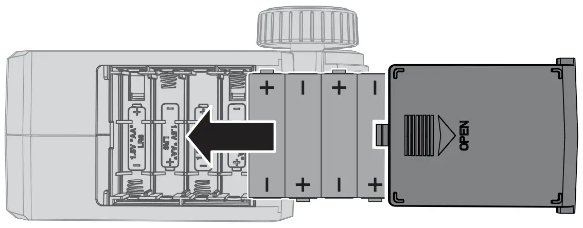
This transmitter requires 4 AA batteries.
- Remove the battery cover from the transmitter.
- Install the batteries as shown.
- Install the battery cover.
![]() CAUTION: If using rechargeable batteries, charge only rechargeable batteries.
CAUTION: If using rechargeable batteries, charge only rechargeable batteries.
Charging non-rechargeable batteries may cause the batteries to burst, resulting in injury to persons and/or damage to property.
![]() CAUTION: Risk of explosion if battery is replaced by an incorrect type. Dispose of used batteries according to national regulations.
CAUTION: Risk of explosion if battery is replaced by an incorrect type. Dispose of used batteries according to national regulations.
For more information on the transmitter, go to www.horizonhobby.com and click on the support tab for the Spektrum STX2 to download the instruction manual.
ESC CALIBRATION
Ensure proper ESC function by calibrating the ESC to your transmitter inputs.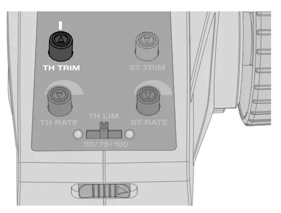
- Power OFF the ESC.
- Ensure your transmitter is powered ON, the throttle is not reversed, the TR TRIM is neutral and the throttle travel range is at 100%.
Disable any special functions such as ABS, etc. - Keep the throttle at neutral and power ON the ESC. The ESC automatically calibrates the throttle range after 3 seconds.
- One long beep will sound when the ESC is ready to run.
BINDING
Binding is the process of programming the receiver to recognize the GUID (Globally Unique Identifier) code of a single specific transmitter. The STX2® transmitter and SPMSRX200 receiver are bound at the factory. If you need to rebind, follow the instructions below: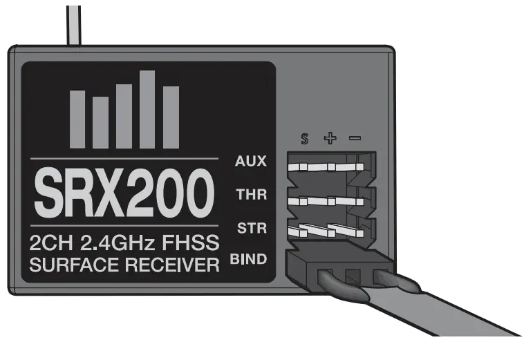
- Insert the Bind Plug in the BIND port of the ESC.
- Connect a fully charged battery to the ESC.
- Power on the ESC. The red receiver LED flashes, indicating the receiver is in bind mode.
- Center the ST TRIM and TH TRIM dials on the transmitter.
- Turn the Steering Wheel to Full Right. Power ON the transmitter while holding the Steering Wheel to the Right.
- Release the Steering Wheel when the receiver LED goes solid.
- Remove the Bind Plug and store it in a convenient place.
- Power OFF the ESC to save the settings.
- Power OFF the transmitter.
You must rebind when:
- When you want different failsafe positions (e.g. when throttle or steering reverse has been changed).
- Binding the receiver to a different transmitter.
NOTICE: Do not attempt to bind the transmitter and receiver if there are other compatible transmitters in bind mode within 400 feet. Doing so may result in unexpected binding.
DRIVING PRECAUTIONS
- Maintain sight of the vehicle at all times.
- Routinely inspect the vehicle for loose wheel hardware.
- Routinely inspect the steering assembly for any loose hardware. Driving the vehicle off-road can cause fasteners to loosen over time.
- Do not drive the vehicle in tall grass. Doing so can damage the vehicle or electronics.
- Stop driving the vehicle when you notice a lack of power. Driving the vehicle when the battery is discharged can cause the receiver to power off. If the receiver loses power, you will lose control of the vehicle. Damage due to an over-discharged Li-Po battery is not covered under warranty.
CAUTION: Do not discharge a Li-Po battery below 3V per cell. Batteries discharged to a voltage lower than the lowest approved voltage may become damaged, resulting in loss of performance and potential fire when batteries are charged. - Do not apply forward or reverse throttle if the vehicle is stuck.
Applying throttle in this instance can damage the motor or ESC. - After driving the vehicle, allow the electronics to cool before driving the vehicle again.
IMPORTANT: Keep wires away from all moving parts.
POWERING ON THE VEHICLE
- Center the ST TRIM and TH TRIM dials on the transmitter.
- Power on the transmitter.
- Install a fully charged battery pack per the Installing the Battery section.
- Power on the ESC.
IMPORTANT: The vehicle MUST remain on a flat, level surface and motionless for at least 5 seconds.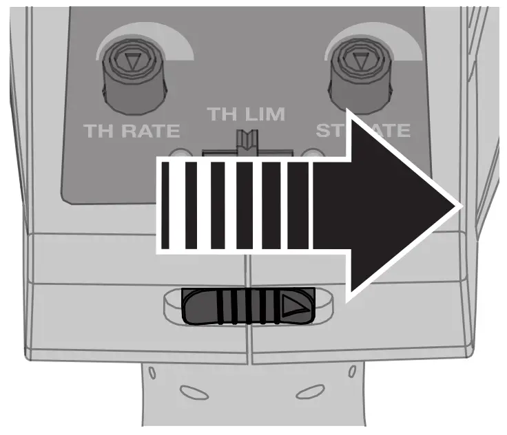
BEFORE RUNNING YOUR VEHICLE
- Check for free suspension movement. All suspension arms and steering components should move freely. Any binds will cause the vehicle to handle poorly.
- Charge a battery pack. Always charge the battery pack as per the battery and/or charger manufacturers’ instructions.
- Set the transmitter steering trim. Follow the instructions to set the steering trim/subtrim so that the vehicle drives straight with no input to the steering.
- Perform a Control Direction Test.
RUN TIME
The largest factor in run time is the capacity of the battery pack. A larger mAh rating increases the amount of run time experienced.
The condition of a battery pack is also an important factor in both run time and speed.
The battery connectors may become hot during driving. Batteries will lose performance and capacity over time.
Driving the vehicle from a stop to full speed repeatedly will damage the batteries and electronics over time. Sudden acceleration will also lead to shorter run times.
TO IMPROVE RUN TIMES
- Keep your vehicle clean and well maintained.
- Allow more airflow to the ESC and motor.
- Change the gearing to a lower ratio. A lower ratio decreases the operating temperature of the electronics. Use a smaller pinion gear or larger spur gear to lower the gear ratio.
- Use a battery pack with a higher mAh rating.
- Use the optimum charger to charge battery packs (Visit your local hobby dealer for more information).
PERFORMING A CONTROL DIRECTION TEST
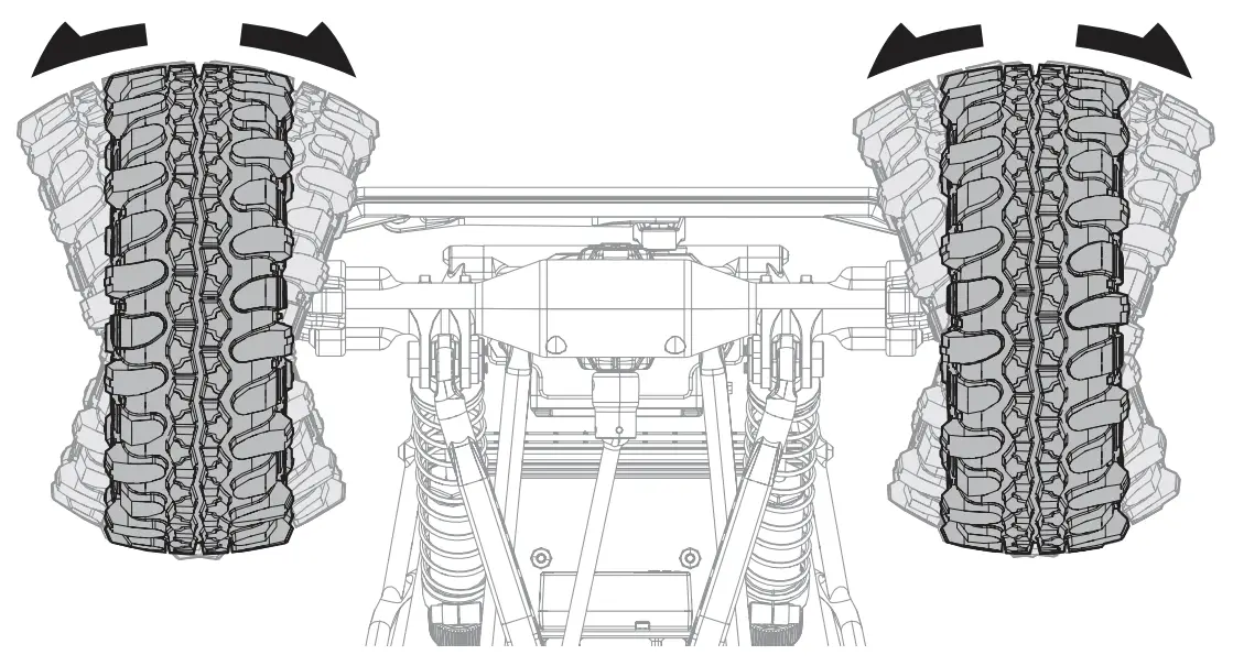
Perform a control test with the vehicle wheels off the ground. If the wheels rotate after the vehicle is powered ON, adjust the TH Trim knob until they stop. To make the wheels move forward, pull the trigger. To reverse them, wait for the wheels to stop, then push the trigger.
When moving forward, the wheels should maintain a straight line without any steering wheel input. If not, adjust the ST Trim knob, so the wheels maintain a straight line without having to turn the steering wheel.
DYNAMITE® 60A WATERPROOF FWD/REV BRUSHED ESC (DYNS2210)
SPECIFICATIONS
| Type | Brushed |
| Constant/Peak | 60A/360A |
| Resistance | 0.0008 Ohms |
| Function | Forward/Brake/Reverse, Forward/Brake, Forward/Reverse (Crawler Mode) |
| Vehicle Type | 1/10 on-road and off-road; 1/10 rock crawler |
| Operation | Proportional forward, proportional reverse with braking delay, Crawler Mode |
| Battery Type/Input Voltage | 2–3 cell Li-Po/Li-Fe; 5–7 cell Ni-MH/Ni-Cd |
| Motor Type | 540-/550-size closed endbell motors: 2S Li-Po down to 12T; 3S Li-Po down to 35T |
| BEC Output | 6V/3A |
| Overload Protection | Thermal |
| Dimensions | 35.6mm x 34mm x 18mm (1.40 in x 1.34 in x 0.71 in) |
| Weight | 40 g (1.41 oz) with wires |
| Battery Connector | EC3™ connector |
| Motor Connector | 3.5mm Tamiya-style bullet |
ESC LED STATUS
- No ESC LEDs will glow when there is no throttle input from the transmitter.
- The red ESC LED glows when there is any throttle input from the transmitter.
AUDIBLE WARNING TONES
- Input Voltage: The ESC checks the in put voltage when it is powered ON. If a voltage problem is detected, the ESC continuously sounds 2 beeps with a 1 second pause (xx-xx-xx). Power OFF the ESC and ensure the connections are secure and that the battery power is not too low for safe operation.
- Radio Connection: The ESC checks radio signal input when it is powered ON.
If a problem is detected, the ESC continuously sounds 1 beep with a 2 second pause (x–x–x). Power OFF the ESC and ensure the radio system is operating correctly.
ESC CALIBRATION PROCEDURE
Ensure proper ESC function by calibrating the ESC to your transmitter inputs.
- Power OFF the ESC.
- Ensure your transmitter is powered ON, the throttle is not reversed, the throttle trim is neutral and the throttle travel range is at 100%. Disable any special functions such as ABS, etc.
- Keep the throttle at neutral and power ON the ESC.
- The ESC automatically calibrates the throttle range after 3 seconds.
One long beep will sound when the ESC is ready to run.
CONNECTING THE ESC
- Connect the RED (+) ESC wire to the RED (+) motor wire.
- Connect the BLACK (–) ESC wire to the BLACK (–) motor wire.
NOTICE: Always disconnect the battery from the ESC when you have finished operating your vehicle. The ESC’s switch only controls power to the receiver and servos.
The ESC will continue to draw current when connected to the battery, resulting in possible damage to the battery through over discharge.
PROGRAMMING
The ESC comes with two jumpers pre-installed in the MODE: F/B (forward/brake) and BATT: Li-Po configurations.
To change the mode to F/B/R (forward/brake/reverse) or F/R (forward/reverse) or change the battery type to Ni-MH.
- Power OFF the ESC.
- Disconnect the jumper from the default port and connect it to the desired port.
- Power ON the ESC.
If the jumpers are lost or not installed, the ESC will default to MODE: F/B/R and BATT: Li-Po.
![]() WARNING: Do not connect bind plugs or receiver servo leads into the ESC programming port. Doing so may damge the ESC and/or components.
WARNING: Do not connect bind plugs or receiver servo leads into the ESC programming port. Doing so may damge the ESC and/or components.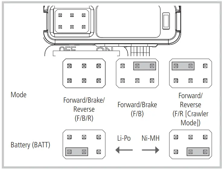
VEHICLE LEDs
Plug the Rock Lights on the vehicle into the AUX CH on the receiver.
Plug the Cage LEDs into the BIND port on the receiver.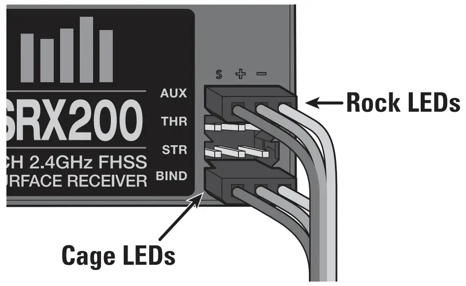
DYNAMITE® 540 BRUSHED MOTOR 35T (DYNS1216)
PRECAUTIONS
- Never touch moving parts.
- Never disassemble while the batteries are installed.
- Always let parts cool before touching.
GEARING
Your vehicle has been equipped with the optimal gearing for the stock platform. It offers an ideal balance between speed, power and efficiency. Should you decide to customize your vehicle with optional batteries or motors, it may be necessary for you to change the pinion or spur gear.
Installing a pinion gear with fewer teeth or a spur gear with more teeth will provide greater torque but will reduce top speed. Likewise, a pinion gear with more teeth or a spur gear with fewer teeth will reduce torque and increase top speed. Care should be taken when installing larger pinion gears as this can “overgear” the vehicle, resulting in overheating of the motor and ESC. When testing different gearing options, pay close attention to the temperature of the motor and speed control to ensure you are operating within the temperature range of the components. The motor or ESC should never be so hot that it cannot be touched. If temperatures are too hot, a different gearing combination with a lower pinion gear and/or higher spur gear is suggested.
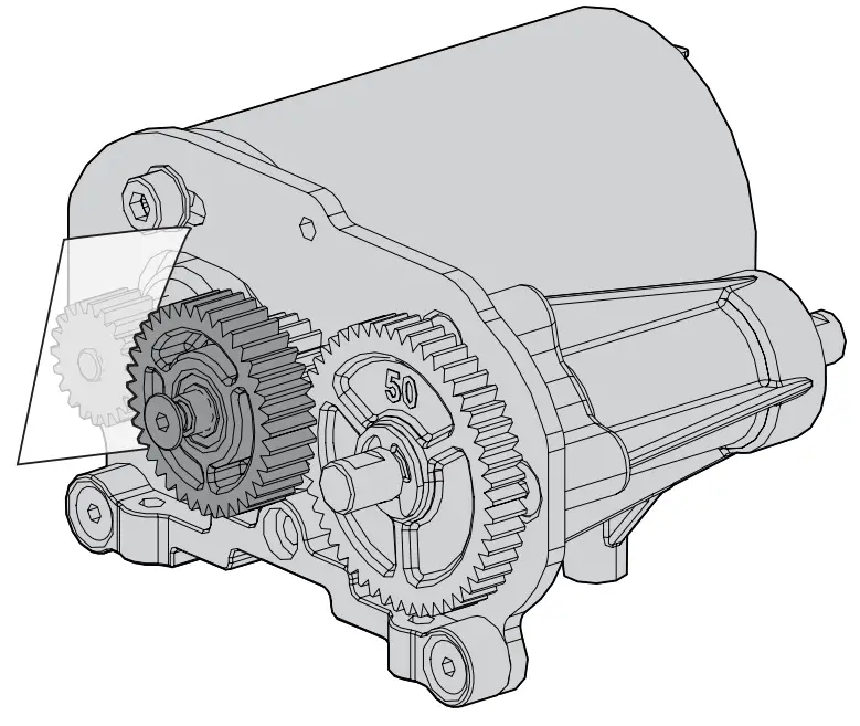
CHANGING THE PINION GEAR/GEAR RATIO
The following instructions are for replacing a worn pinion gear. If you are changing the pinion gear size please refer to “Setting the Gear Mesh.”
- Loosen the pinion gear set screw to remove the installed pinion gear.
- Loosen the motor screws and slide the motor back.
- Place the new pinion on the end of the motor shaft so the set screw is located over the flat area on the shaft.
- Position the teeth on the pinion gear so they line up with the spur gear and secure the pinion gear onto the motor shaft by tightening the set screw.
SETTING THE GEAR MESH
The gear mesh has already been set at the factory. Setting it is only necessary when changing motors or gears.
Proper gear mesh (how gear teeth meet) is important to the performance of the vehicle. When the gear mesh is too loose, the spur gear could be damaged by the pinion gear on the motor.
If the mesh is too tight, speed could be limited and the motor and ESC will overheat.
- Loosen the motor screws and slide the motor back.
- Put a small piece of paper between the pinion and spur gears.
- Push the gears together with moderate pressure and hold in place while tightening the motor screws.
- Remove the paper. Check the mesh at 3–5 different locations around the spur gear for minimal movement.

TROUBLESHOOTING GUIDE
| PROBLEM | POSSIBLE CAUSE | SOLUTION |
| Vehicle does not operate | Battery not charged or plugged in | Charge battery/plug in |
| ESC switch not “On” | Turn on ESC switch | |
| Transmitter not “On” or low battery | Turn on/replace batteries | |
| Motor runs but wheels do not rotate | Pinion not meshing with spur gear | Adjust pinion/spur mesh |
| Pinion spinning on motor shaft | Tighten pinion gear setscrew on motor shaft flat spot | |
| Transmission gears stripped | Replace transmission gears | |
| Drive pin broken | Check and replace drive pin | |
| Steering does not work | Servo plug not in receiver properly | Make sure the steering servo plug is connected to the receiver steering channel, noting proper polarity |
| Servo gears or motor damaged | Replace or repair servo | |
| Will not turn one direction | Servo gears damaged | Replace or repair servo |
| Motor does not run | Motor wire solder joint is damaged | Resolder the motor wire with the proper equipment |
| Motor wire broken | Repair or replace as needed | |
| ESC damaged | Contact Horizon Hobby Product Support | |
| ESC gets hot | Motor over-geared | Use smaller pinion or larger spur gear |
| Driveline bound up | Check wheels and transmission for binding | |
| Poor run time and/or sluggish acceleration | Battery pack not fully charged | Recharge battery |
| Charger not allowing full charge | Try another charger | |
| Driveline bound up | Check wheels, transmission for binding | |
| Poor range and/or glitching | Transmitter batteries low | Check and replace |
| Vehicle battery low | Recharge battery | |
| Loose plugs or wires | Check all wire connections and plugs |
LIMITED WARRANTY
What this Warranty Covers
Horizon Hobby, LLC, (Horizon) warrants to the original purchaser that the product purchased (the “Product”) will be free from defects in materials and workmanship at the date of purchase.
What is Not Covered
This warranty is not transferable and does not cover (i) cosmetic damage, (ii) damage due to acts of God, accident, misuse, abuse, negligence, commercial use, or due to improper use, installation, operation or maintenance, (iii) modification of or to any part of the Product, (iv) attempted service by anyone other than a Horizon Hobby authorized service center, (v) Product not purchased from an authorized Horizon dealer, or (vi) Product not compliant with applicable technical regulations or (vii) use that violates any applicable laws, rules, or regulations. OTHER THAN THE EXPRESS WARRANTY ABOVE, HORIZON MAKES NO OTHER WARRANTY OR REPRESENTATION, AND HEREBY DISCLAIMS ANY AND ALL IMPLIED WARRANTIES, INCLUDING, WITHOUT LIMITATION, THE IMPLIED WARRANTIES OF NON-INFRINGEMENT, MERCHANTABILITY AND FITNESS FOR A PARTICULAR PURPOSE. THE PURCHASER ACKNOWLEDGES THAT THEY ALONE HAVE DETERMINED THAT THE PRODUCT WILL SUITABLY MEET THE REQUIREMENTS OF THE PURCHASER’S INTENDED USE.
Purchaser’s Remedy
Horizon’s sole obligation and purchaser’s sole and exclusive remedy shall be that Horizon will, at its option, either (i) service, or (ii) replace, any Product determined by Horizon to be defective. Horizon reserves the right to inspect any and all Product(s) involved in a warranty claim. Service or replacement decisions are at the sole discretion of Horizon. Proof of purchase is required for all warranty claims. SERVICE OR REPLACEMENT AS PROVIDED UNDER THIS WARRANTY IS THE PURCHASER’S SOLE AND EXCLUSIVE REMEDY.
Limitation of Liability
HORIZON SHALL NOT BE LIABLE FOR SPECIAL, INDIRECT, INCIDENTAL OR CONSEQUENTIAL DAMAGES, LOSS OF PROFITS OR PRODUCTION OR COMMERCIAL LOSS IN ANY WAY, REGARDLESS OF WHETHER SUCH CLAIM IS BASED IN CONTRACT, WARRANTY, TORT, NEGLIGENCE, STRICT LIABILITY OR ANY OTHER THEORY OF LIABILITY, EVEN IF HORIZON HAS BEEN ADVISED OF THE POSSIBILITY OF SUCH DAMAGES. Further, in no event shall the liability of Horizon exceed the individual price of the Product on which liability is asserted. As Horizon has no control over use, setup, final assembly, modification or misuse, no liability shall be assumed nor accepted for any resulting damage or injury. By the act of use, setup or assembly, the user accepts all resulting liability. If you as the purchaser or user are not prepared to accept the liability associated with the use of the Product, purchaser is advised to return the Product immediately in new and unused condition to the place of purchase.
Law
These terms are governed by Illinois law (without regard to conflict of law principals). This warranty gives you specific legal rights, and you may also have other rights which vary from state to state. Horizon reserves the right to change or modify this warranty at any time without notice.
WARRANTY SERVICES
Questions, Assistance, and Services
Your local hobby store and/or place of purchase cannot provide warranty support or service.
Once assembly, setup or use of the Product has been started, you must contact your local distributor or Horizon directly. This will enable Horizon to better answer your questions and service you in the event that you may need any assistance. For questions or assistance, please visit our website at www.horizonhobby.com, submit a Product Support Inquiry, or call the toll free telephone number referenced in the Warranty and Service Contact Information section to speak with a Product Support representative.
Inspection or Services
If this Product needs to be inspected or serviced and is compliant in the country you live and use the Product in, please use the Horizon Online Service Request submission process found on our website or call Horizon to obtain a Return Merchandise Authorization (RMA) number. Pack the Product securely using a shipping carton. Please note that original boxes may be included, but are not designed to withstand the rigors of shipping without additional protection. Ship via a carrier that provides tracking and insurance for lost or damaged parcels, as Horizon is not responsible for merchandise until it arrives and is accepted at our facility.
An Online Service Request is available at http://www.horizonhobby.com/content/servicecenter_render-service-center.If you do not have internet access, please contact Horizon Product Support to obtain a RMA number along with instructions for submitting your product for service. When calling Horizon, you will be asked to provide your complete name, street address, email address and phone number where you can be reached during business hours.
When sending product into Horizon, please include your RMA number, a list of the included items, and a brief summary of the problem. A copy of your original sales receipt must be included for warranty consideration. Be sure your name, address, and RMA number are clearly written on the outside of the shipping carton.
NOTICE: Do not ship Li-Po batteries to Horizon. If you have any issue with a Li-Po battery, please contact the appropriate Horizon Product Support office.
Warranty Requirements
For Warranty consideration, you must include your original sales receipt verifying the proof-of-purchase date. Provided warranty conditions have been met, your Product will be serviced or replaced free of charge. Service or replacement decisions are at the sole discretion of Horizon.
Non-Warranty Service
Should your service not be covered by warranty, service will be completed and payment will be required without notification or estimate of the expense unless the expense exceeds 50% of the retail purchase cost. By submitting the item for service you are agreeing to payment of the service without notification. Service estimates are available upon request. You must include this request with your item submitted for service.
Non-warranty service estimates will be billed a minimum of ½ hour of labor. In addition you will be billed for return freight. Horizon accepts money orders and cashier’s checks, as well as Visa, MasterCard, American Express, and Discover cards. By submitting any item to Horizon for service, you are agreeing to Horizon’s Terms and Conditions found on our website http://www.horizonhobby.com/content/service-center_render-service-center.
ATTENTION: Horizon service is limited to Product compliant in the country of use and ownership. If received, a non-compliant Product will not be serviced.
Further, the sender will be responsible for arranging return shipment of the un-serviced Product, through a carrier of the sender’s choice and at the sender’s expense. Horizon will hold non-compliant Product for a period of 60 days from notification, after which it will be discarded.
WARRANTY AND SERVICE CONTACT INFORMATION
| Country of Purchase | Horizon Hobby | Contact Information | Address |
| United States of America | Horizon Service Center (Repairs and Repair Requests) | servicecenter.horizonhobby.com/RequestForm/ | 4105 Fieldstone Rd. Champaign, Illinois 61822 USA |
| Horizon Product Support (Product Technical Assistance) | [email protected] 877-504-0233 | ||
| Sales | [email protected] 800-338-4639 | ||
| European Union | Horizon Technischer Service | [email protected] +49 (0) 4121 2655 100 | Hanskampring 9 D 22885 Barsbüttel, Germany |
| Sales: Horizon Hobby GmbH |
FCC STATEMENT
FCC ID: 2AI3D-SS0001
This equipment has been tested and found to comply with the limits for Part 15 of the FCC rules.
These limits are designed to provide reasonable protection against harmful interference in a residential installation. This equipment generates uses and can radiate radio frequency energy and, if not installed and used in accordance with the instructions, may cause harmful interference to radio communications.
However, there is no guarantee that interference will not occur in a particular installation. If this equipment does cause harmful interference to radio or television reception, which can be determined by turning the equipment off and on, the user is encouraged to try to correct the interference by one or more of the following measures:
- Reorient or relocate the receiving antenna.
- Increase the separation between the equipment and receiver.
- Connect the equipment to an outlet on a circuit different from that to which the receiver is connected.
This device complies with part 15 of the FCC rules. Operation is subject to the following two conditions: (1) This device may not cause harmful interference, and (2) this device must accept any interference received, including interference that may cause undesired operation.
NOTICE: Modifications to this product will void the user’s authority to operate this equipment.
RF Radiation Exposure Statement
- This Transmitter must not be co-located or operating in conjunction with any other antenna or transmitter.
- This equipment complies with FCC RF radiation exposure limits set forth for an uncontrolled environment. This equipment should be installed and operated with a minimum distance of 20 centimeters between the radiator and your body.
Antenna Separation Distance
When operating your Spektrum transmitter, please be sure to maintain a separation distance of at least 20 cm between your body (excluding fingers, hands, wrists, ankles and feet) and the antenna to meet RF exposure safety requirements as determined by FCC regulations.
The illustration shows the approximate 20 cm RF exposure area and typical hand placement when operating your Spektrum transmitter.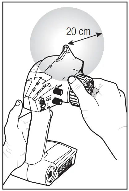
IC INFORMATION
IC: 21682-SSTC9202
This device complies with Industry Canada licence-exempt RSS standard(s).
Operation is subject to the following two conditions: (1) this device may not cause interference, and (2) this device must accept any interference, including interference that may cause undesired operation of the device.
COMPLIANCE INFORMATION FOR THE EUROPEAN UNION
 EU Compliance Statement: Horizon Hobby, LLC hereby declares that this product is in compliance with the essential requirements and other relevant provisions of the RED and EMC Directive.
A copy of the EU Declaration of Conformity is available online at:
http://www.horizonhobby.com/content/support-render-compliance.
Instructions for disposal of WEEE by users in the European Union
 This product must not be disposed of with other waste. Instead, it is the user’s responsibility to dispose of their waste equipment by handing it over to a designated collections point for the recycling of waste electrical and electronic equipment. The separate collection and recycling of your waste equipment at the time of disposal will help to conserve natural resources and ensure that it is recycled in a manner that protects human health and the environment. For more information about where you can drop off your waste equipment for recycling, please contact your local city office, your household waste disposal service or where you purchased the product.
REPLACEMENT PARTS
| Part # | Parts |
| DYN3205 | 4 x 8 Unflanged Ball Bearing |
| DYNS1216 | Dynamite 35T 540 Brushed Motor |
| DYNS2210 | WP 60A FWD/REV Brushed ESC |
| LOS230005 | LED Light Board and Housing |
| LOS230047 | Roll Cage Set |
| LOS230048 | Accessory Pack |
| LOS230049 | 3-Way Splitter |
| LOS230050 | Body Set w/Drivers, Clear |
| LOS231004 | Side Plate Set, Chassis, Black |
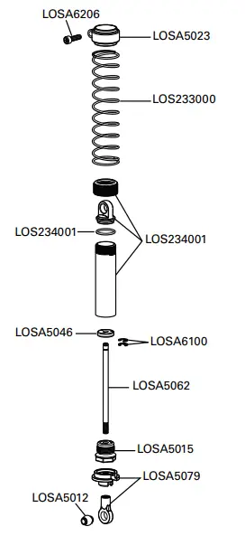
| LOS233000 | 2.5″ Spring 3.4 Rate, Black (4) |
| LOS234001 | 1.2″ Shock Body, Silver (4) |
| LOS235003 | M3 x 6mm Cap Head Screws (10) |
| LOS4120 | 48 Pitch Pinion Gear, 20T |
| LOSA1030 | Spindle and Carrier Set |
| LOSA1033 | Upper Suspension Link Mount |
| LOSA1034 | Lower Suspension Link, Mounts and Pin |
| LOSA1517 | Steering King Pins and Hardware |
| LOSA2030 | Rear Outer Hub, Cap and Hardware |
| LOSA3184 | Rear Axle |
| LOSA3185 | Rear Axle Spacer Set, Aluminium |
| LOSA3187 | HD Worm Gear Set, 21T (2) |
| LOSA3194 | Front & Center CV Rebuild Kit |
| LOSA3196 | Front CV Drive Shaft Set, HD |
| LOSA3197 | Front CV Axle HD |
| LOSA3198 | Front CV Drive Shaft HD |
| LOSA3199 | CV Pin Retainer Clip 11mm Pins |
| LOSA4009 | Battery Straps, Hook/Loop (2) |
| LOSA4012 | Front/Rear Axle Case Set |
| LOSA4036 | ESC Platform |
| LOSA4037 | Servo Mnts, Plate and Hardware |
| LOSA4039 | Transmission Skid Plate: CCR |
| LOSA5012 | Upper Shock Bushings and Lower Shock Pivot Ball (4) |
| LOSA5015 | Double O-Ring Shock Cartridge |
| LOSA5023 | Shock Spring Clamps & Cups |
| LOSA5062 | Shock Shaft,1.2″ Ti-Nitride |
| LOSA5079 | Shock Ends and Cups (4) |
| LOSA6045 | HD Steering Link Set |
| LOSA6100 | 1/8″ E-Clips |
| LOSA6109 | E-Clips, 5mm (12) |
| LOSA6201 | 3mm x 6mm Socket Head Screw |
| LOSA6206 | 4-40 x 3/8″ Socket Head Screws (10) |
| LOSA6210 | 4-40 x 3/8″ Flat Head Socket |
| LOSA6213 | 4-40 x 1/4″ Flat Socket Screw (6) |
| LOSA6221 | 4-40 x 5/8″ Cap Screws (6) |
| LOSA6228 | 5-40 x 1/8″ Hardened Setscrews (10) |
| LOSA6229 | 4-40 x 3/8″ Button Head Screws |
| LOSA6245 | 4-40 x 5/16″ Button Head Screws (10) |
| LOSA6248 | 4-40 Setscrew Assortment (11) |
| LOSA6256 | 4-40 x 1/2 Button Head Cap Screw (6) |
| LOSA6258 | 2-56 x 5/16″ Flathead Screws (24) |
| LOSA6269 | 4-40 x 5/16″ Flathead Screw (6) |
| LOSA6294 | 2-56 x 5/16″ Cap Screw (6) |
| LOSA6306 | 4-40 Aluminum Mini-Nuts (10) |
| LOSA6308 | 4-40 Steel Locking 1/2 Nuts (10) |
| LOSA6350 | #4 and 1/8″ Hardened Washers |
| LOSA6358 | Shim Set |
| LOSA6937 | 5 x 10mm Shielded Ball Bearing (2) |
| LOSA6940 | 6 x 12mm Sealed Ball Bearing (4) |
| LOSA6947 | 5 x 11 x 4mm Rubber Sealed Ball Bearing (4) |
| LOSA6956 | 12 x 18 x 4mm Ball Bearing (2) |
| LOSB2034 | Lower Track Rods |
| LOSB2036 | Steering Track Rod & Bushings |
| LOSB2037 | Upper Track Rods |
| LOSB2291 | Battery Tray |
| LOSB2370 | Servo Arm & Metal Insert |
| LOSB3012 | Center Tranny Case and Supports |
| LOSB3013 | Center Transmission Gear Set |
| LOSB3014 | Center Transmission Shaft/Pin Set |
| LOSB3018 | Motor Plate, Black |
| LOSB3525 | 12mm Molded Hex Pins and Lock Nuts (4) |
| LOSB3580 | Center CV Drive Shaft |
| LOSB3581 | Center Drive Shaft Cup Adapter |
| LOSB3582 | Center Drive Shaft CV Yoke, Coupler, Hardware |
| LOSB3583 | Center CV Drive Shaft Set |
| LOSB9996 | LED Light Set |
| SPMSRX200 | SRX200 2-CH 2.4 GHz FHSS RX |
| SPMSTX200 | STX2 2-CH 2.4 GHz FHSS Radio System |
| TLR5902 | M3 x 8mm Button Head Screws (10) |
| TLR5913 | M2.5 x 12mm Button Head Screws (10) |
| TLR6312 | M2.5 x .45 x 5mm Locknut (6) |
| TLR6352 | M3 Washers (10) |
| TLR8202 | Body Clips, Black (12) |
| TLR255001 | M2.5 x 5mm Button Head Screws (10) |
| TLR336000 | 4mm Aluminium Serrated Lock Nuts, Black (6) |
| TLR235008 | M3 x 6mm Flat Head Screws (10) |
| TLR74006 | Silicone Shock Oil, 30 wt, 2 oz |
| VTR43000 | Beadlock Wheel with Rings (2) |
| VTR43018 | TSL SX Swamper 1.9 Tire w/Insert |
RECOMMENDED PARTS
| Part # | English |
| DYN1070EC | Speedpack 7.2V 3300mAh NiMH 6C Flat: EC3 |
| DYN9004EC | 7.4V 5000mAh 2S 20C LiPo, Hardcase: EC3 |
| DYNC2000CA | Prophet Sport NiMH 35W AC Charger |
| DYNC2005CA | Prophet Sport LiPo 35W AC Charger |
| DYNC2010CA | Prophet Sport Plus 50W AC/DC Charger |
OPTIONAL PARTS
| Part # | English |
| DYNC3000 | Ultra 100W AC/DC Touch Charger |
| DYNT0501 | Start Up Tool Set |
| DYN9005EC | 7.4V 5000mAh 2S 30C LiPo, Hardcase: EC3 |
| DYNB3802EC | 7.4V 5000mAh 2S 50C LiPo, Hardcase: EC3 |
| DYNB3850EC | 7.6V HV 4000mAh 2S 50C LiPo Hardcase |
| DYNB3852EC | 7.6V HV 5000mAh 2S 50C LiPo Hardcase: EC3 |
| LOS43005 | 2.2 Beadlock Wheels, Chrome with Red Rings (2) |
| LOSA3186 | 12 mm Alumnum 5.7 mm (wide) Hex (4) |
| LOSA7682B | Front/Rear Rock Claws 2.2 Tires w/Foam, Blue (2) |
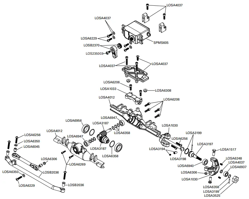
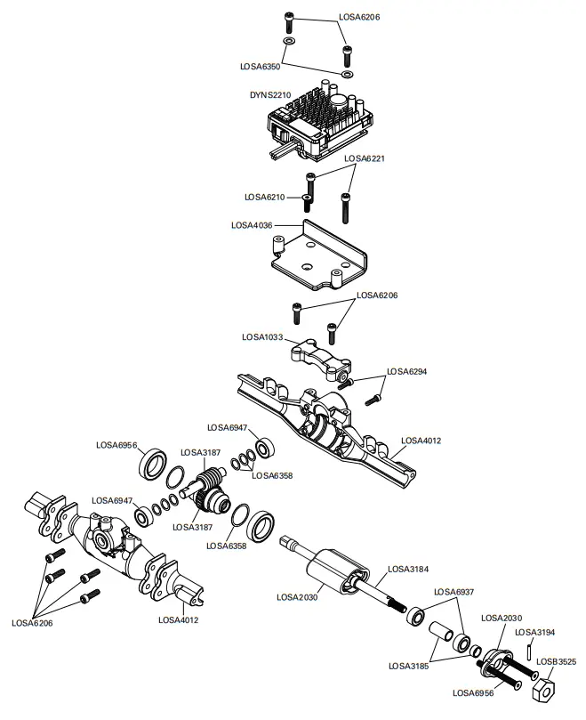
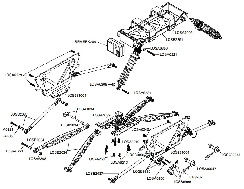
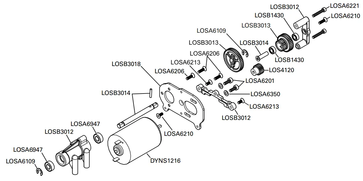
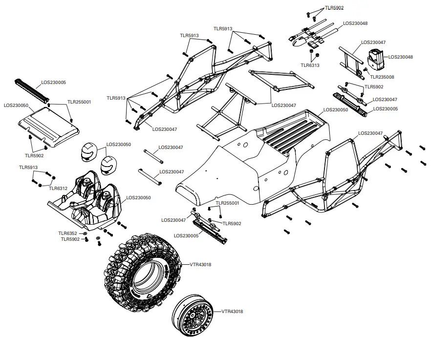
EXPLODED VIEW
©2018 Horizon Hobby, LLC.
Losi, STX2, DSM, DSM2, DSMR, EC3, Dynamite, Fuze, Prophet and the Horizon Hobby logo are trademarks or registered trademarks of Horizon Hobby, LLC.
The Spektrum trademark is used with permission of Bachmann Industries, Inc.

References
 RC Airplanes and Helicopters, RC Cars and Trucks, RC Boats, RC Radios | Horizon Hobby
-
Horizon Hobby Service Center
 Product Service Center - Request Form
-
RC Airplanes and Helicopters, RC Cars and Trucks, RC Boats, RC Radios | Horizon Hobby
-
RC Airplanes and Helicopters, RC Cars and Trucks, RC Boats, RC Radios | Horizon Hobby
-
Horizon Hobby Compliance Information
-
The leaders in RC car and truck innovation and design | Losi


