BAVARIA 301 Sailing Yacht Main Panel
Introduction and Overview
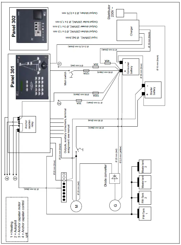
Two panels are available for the operation and power supply. Panel 301 is designed for central monitoring and control of all electrical functions on board the yacht. Panel 302 supplies the 230V devices with power when there is a land connection.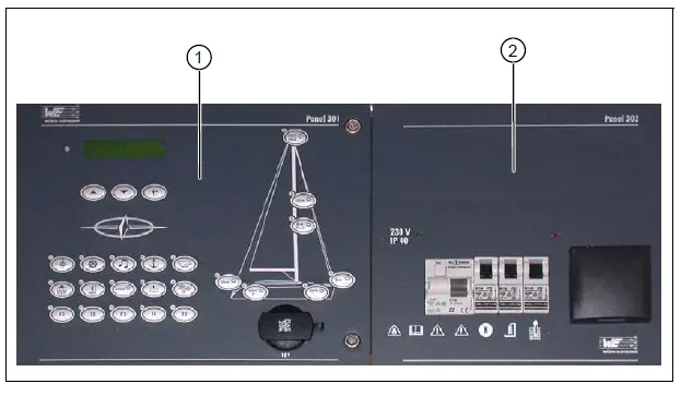
Fig. 1 Overview – panel 301/302
Key
- Panel 301
- Panel 302
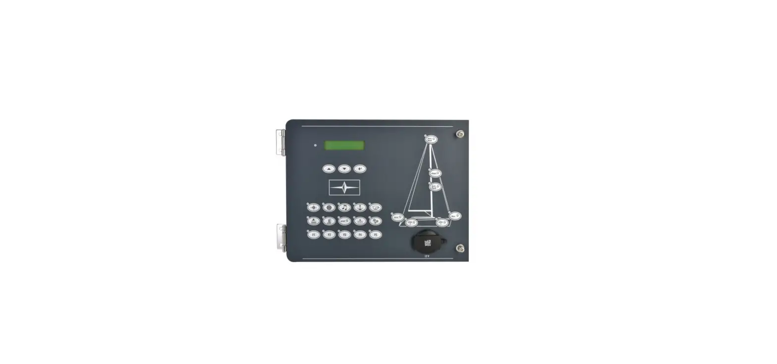
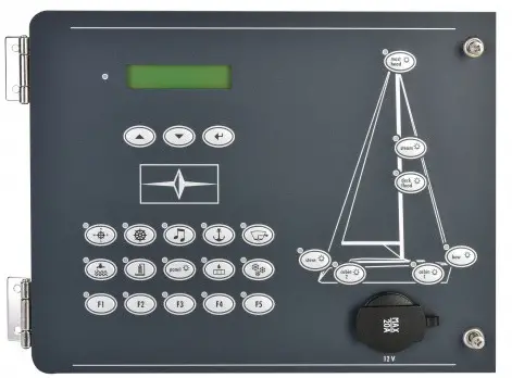
Panel 301 Controls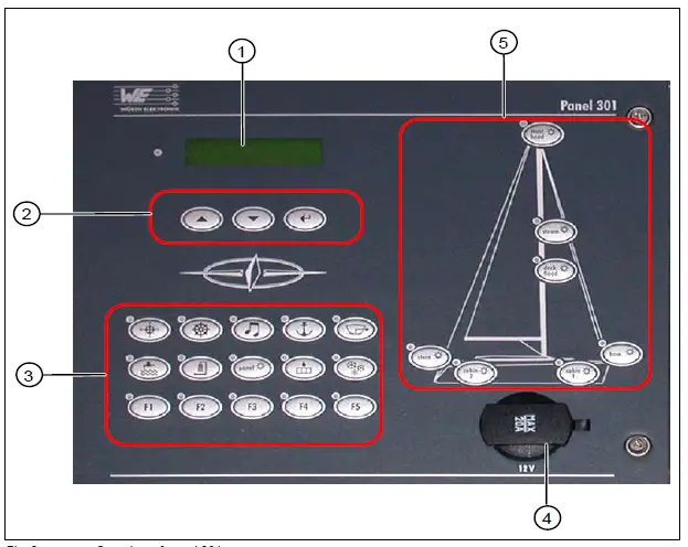 Fig. 2 Overview of panel 301
Key
- Display
- Scroll and acknowledgment buttons
- Socket 12V/20A
- Function buttons
- Lighting buttons
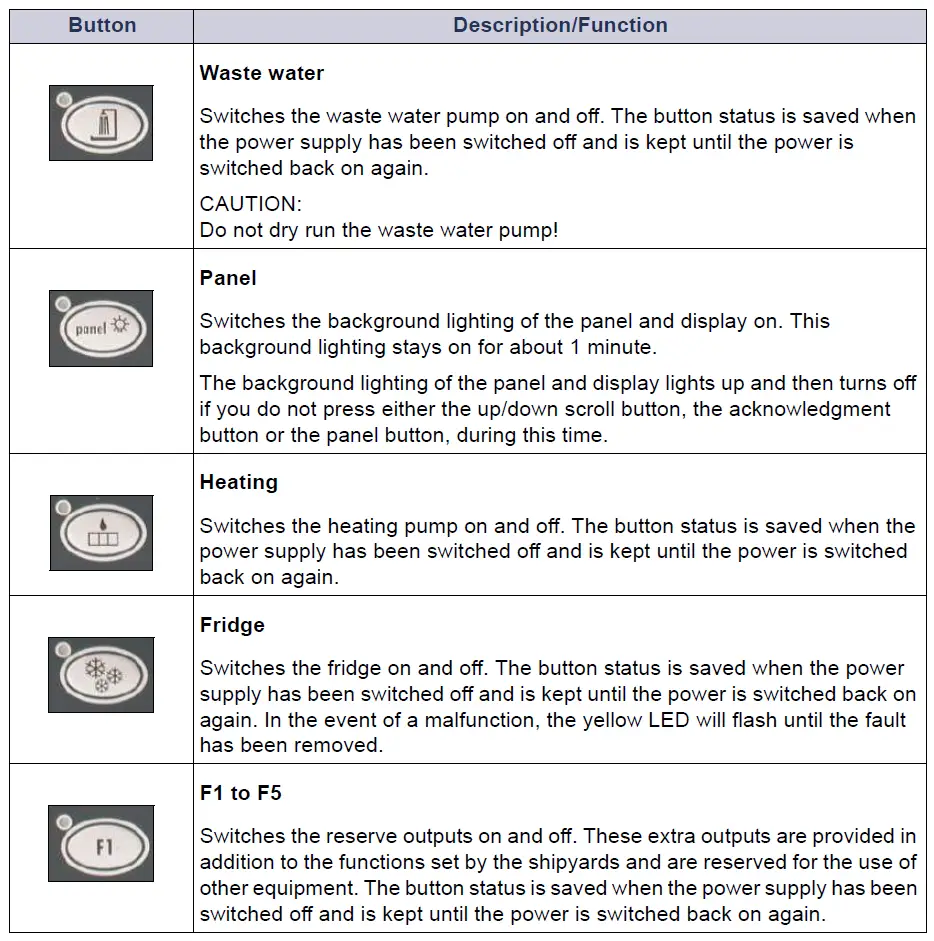
The current status of the function and lighting buttons is shown by the respective LED.
| LED Status | Meaning |
| Yellow LED on | Button function is switched on |
| Yellow LED flashes | Malfunction |
| Yellow LED off | Button function is switched off |
Function Buttons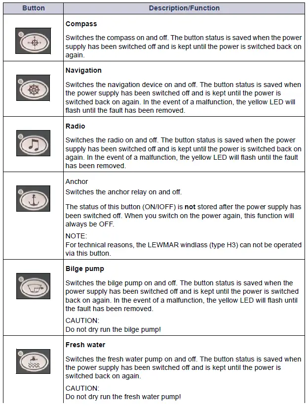
Lighting Buttons
These buttons are used to switch the various lighting sources on and off. The button status is saved when the power supply has been switched off and is kept until the power is switched back on again.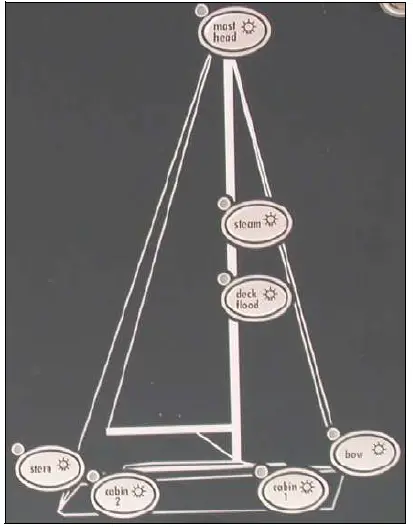
Fig. 3 Detailed view of the lighting buttons
Outside lighting
The yellow LED will flash in the event of a malfunction.
- Stern
- Bow
- Steam
- Mast head
No function monitoring for:
- Deck flood
Inside lighting
- Cabin 1
- Cabin 2
This section describes how to access the various menu functions and how to change settings. 1 As soon as the panel is connected to the power source, a function test will be performed and the LEDs will light up for approx. 1 second. After this, the panel is ready for operation. Alarms will be shown when triggered. See also section 1.2.2.
After activating the main switch, you will see the following start screen on the display:
With the help of the scroll buttons and the acknowledgment button, you can select and view the various information and menus.
You can now perform the required settings at the panel.
Menu
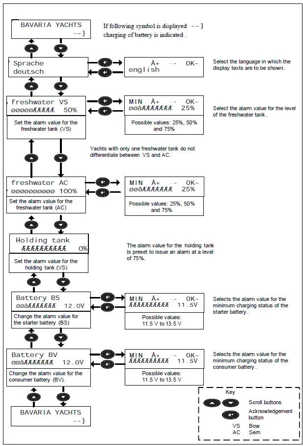
Alarms
If an alarm is triggered, the red LED next to the display will flash. The display will show the menu which has issued the alarm and the alarm itself will be shown by a flashing exclamation mark next to the menu bar. To acknowledge the alarm, press the acknowledgment button for 2 seconds. 1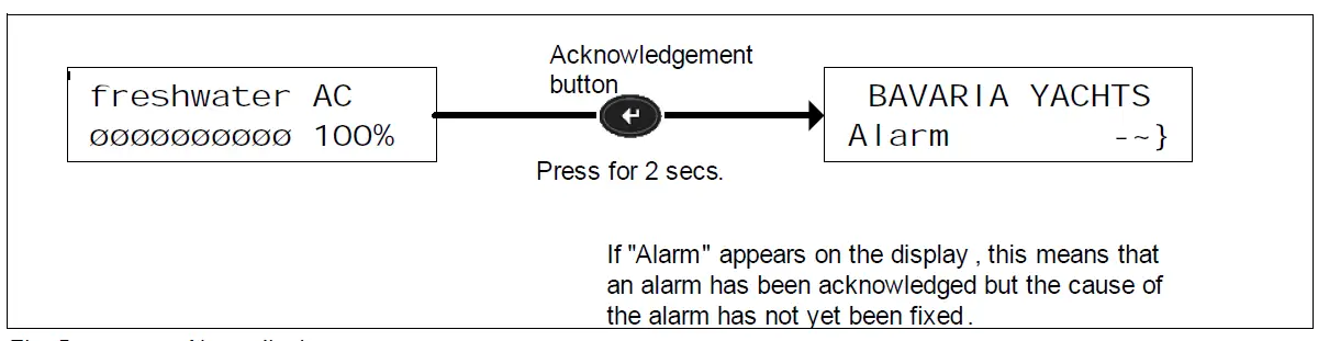
The red LED extinguishes when you acknowledge the alarm.
Overview of Panel 302
Panel 302 supplies the 230V devices with power when there is a land connection.
WARNING
Observe the current consumption and power input
- The consumer devices connected must not exceed a total power input of 3.600 W and a max current consumption of 16 A.

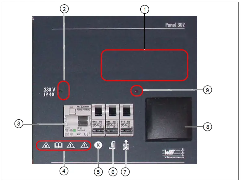
Fig. 6 Overview of panel 302
Key
- Installation point for radio (optional)
- LED (green) for residual current circuit breaker
- Residual current circuit breaker FI /B16
- Observe warning symbols
- Automatic circuit breaker – kitchen (16A)
- Automatic circuit breaker – shower (16A)
- Automatic circuit breaker – boiler (16A)
- Socket 220V (9) LED (red) for boiler on
Function description
- When the residual current circuit breaker is switched on, a green LED indicates the existing land connection.
- The red LED indicates that the heating boiler is switched on.
- The residual current circuit breaker and fuse B16 are connected upstream of the three auto-matic circuit breakers (5,6,7).
- The kitchen fuse also serves the integrated socket (8).
Warning Symbols on Panel 302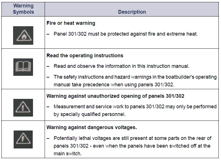
Electrical Connections
Safety Instructions
DANGER
Panel 302 is supplied with 230 V~ ± 5 %, 50/60 Hz line voltage.
- Potentially lethal voltages are therefore still present at some parts on the rear of this panel (in-put B16/FI) – even when the panel has been switched off at the residual current circuit breaker.
- Measurement and service work to panels 301/302 may only be performed by specially quali-fied personnel.
- Incorrect usage of panels 301/302 may cause serious or even lethal injuries and considerable damage to property.
- The safety instructions and hazard warnings in the boatbuilder’s operating manual take prece-dence when using panels 301/302.
- Observe the applicable accident prevention and DIN regulations (particularly DIN EN 60 204, Part 1) or the respective regulations in your country.
- Before performing any service or maintenance work, always switch off panel 302 at the resid-ual current circuit breaker and disconnect it from the power supply.
- Secure the panel to prevent unauthorized reconnection of the power supply. Touching live parts can lead to serious or lethal injuries.
Rear View of Panel 301
The connections and micro-fuses can be found on the rear of the operating panel 301. Loosen the two fastening screws at the front and swing the panel open to the side.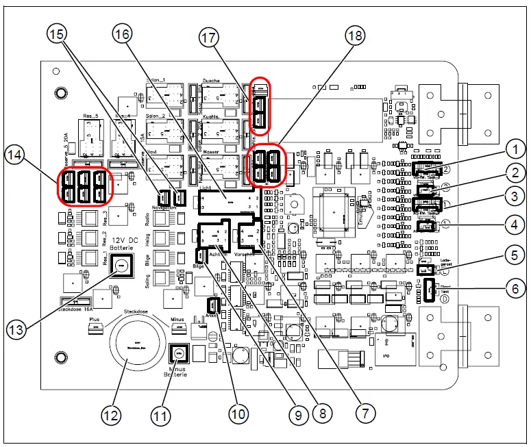
Fig. 7 Rear view of the panel 301 – terminal assignment
Key
- Monitoring of fresh water tank 2 (bow)
- Monitoring of waste tank 2
- Monitoring of fresh water tank 1 (AC)
- Monitoring of waste tank 1
- Monitoring of charger
- Monitoring of diesel tank (not used)
- Bow cable (not used)
- Stern cable
- Bilge pump
- Anchor
- Battery – negative pole
- Socket 12V with fuse
- Battery – positive pole 12C DC
- Reserve function buttons F1-F5
- Shower suction extractor pump
- Light cable
- Shower suction extractor pump
- Fridge
Terminal Assignment
| Connector | [1] Monitoring fresh water tank 2 (bow) | Cable |
| 1 | Fresh water tank 2 | 4/4, wt |
| 2 | Fresh water tank 2 | 3/4, br |
| 3 | Fresh water tank 2 | 2/4, gr |
| 4 | Fresh water tank 2 | 1/4, ye |
| 5 | Fresh water tank 2 | COM/GND |
| Connector | [2] + [4] Monitoring waste tank | Cable |
| 1 | Waste tank 1 | 3/4 |
| 2 | Waste tank 2 | COM/GND |
| Connector | [3] Monitoring fresh water tank 1 (stern) | Cable |
| 1 | Fresh water tank 1 | 4/4, wt |
| 2 | Fresh water tank 1 | 3/4, br |
| 3 | Fresh water tank 1 | 2/4, gr |
| 4 | Fresh water tank 1 | 1/4, ye |
| 5 | Fresh water tank 1 | COM/GND |
| Connector | [5] Monitoring charger | Cable |
| 1 | GND input | — |
| 2 | LED input | — |
| Connector | [6] Monitoring diesel tank | Cable |
| 1 | Not used | — |
| 2 | Not used | — |
| 3 | Not used | — |
| Connector | [7] Bow cable (only for Match series) | Cable |
| 1 | Top light – not used | 1 |
| 2 | Steam light – not used | 2 |
| 3 | Sailing light – not used | 3 |
| 4 | Fresh water pump – not used | 12 |
| Connector | [8] Stern cable, plus option cable | Cable | Description | Connectio n |
| 1 | Stern light | 1 | Function monitoring Button | 10W/2A |
| 2 | Compass light | 2 | No function monitoring Button | 10W/1A |
| 3 | Fresh water pump | 3 | No function monitoring Button | 90W/8A |
| 4 | Navigation instrument | 4 | Monitoring fuses | 240W/20A |
| (autopilot and chart plotter option) | [item14] factory configuratio n or [item15] optional | Button | ||
| 5 | Fresh water pump | 5 | No function monitoring Button | 90W/8A |
| Connector | [9] Bilge pump | Cable | Description | Connectio n |
| Bilge pump | 11 | Function monitoring Button Pump 12V | 80W/10A |
| Connector | [10] Windlass | Cable | Description | Connectio n |
| Windlass | 10 | No function monitoring Button Control external power relay | 60W/5A |
| Connector | [12] Socket | Cable | Description | Connectio n |
| Socket 12V | 17 | No function monitoring NOT switched | 192W/16A |
| Connector | [14] Reserved for function buttons F1-F5 | Cable | Description | Connectio n |
| 1 | Reserve button 1 | — | No function monitoring Button | 60W/5A |
| 2 | Reserve button 2 | — | No function monitoring Button | 60W/5A |
| 3 | Reserve button 3 | — | No function monitoring Button | 60W/5A |
| 4 | Reserve button 4 | — | No function monitoring Button | 180W/15A |
| 5 | Reserve button 5 | — | No function monitoring Button | 240W/20A |
| Connector | [16] Light cable | Cable | Description | Connectio n |
| 1 | 12 V battery 1+, starter battery, connection only for measuring battery | 1 | — | — |
| 2 | !Not connected, occupied internally! | — | — | — |
| 3 | Top light | 3 | Function monitoring Button | 10W/1A |
| 4 | Steam light | 4 | Function monitoring Button | 25W/2A |
| 5 | Bow light | 5 | Function monitoring Button | 25W/2A |
| 6 | Sailing light | 6 | No function monitoring Button | 50W/4A |
| 7+8 | Inside lighting 1+2 | 7+8 | No function monitoring Button | 240W/20A |
| 9+10 | Inside lighting 3+4 | 9+10 | No function monitoring Button | 240W/20A |
| Connector | [16] Light cable | Cable | Description | Connectio n |
| 11 | Heating | 11 | No function monitoring Button Control line for thermostat | 60W/5A |
| 12 | Radio (optional) | 12 | Function monitoring Button | 120W/10A |
| CB radio (optional) | — | Function monitoring Button |
| Connector | [17] Sower suction extractor pump | Cable | Description | Connectio n |
| Shower suction extractor pump | 13+13a+ 13b | No function monitoring Button | 270W/30A |
| Connector | [18] Fridge | Cable | Cable | |
| Cooling unit | 16+16a+ 16b+16c | Monitoring fuses Button | 360W/30A |
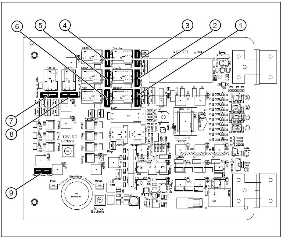
Fig. 8 Rear view of the panel 301 – micro-fuses
Key
- Water pump (10A)
- Cooling unit (30A)
- Shower pump (30A)
- Inside lighting cabin 1 (20A)
- Inside lighting cabin 2 (20A)
- Navigation (20A)
- Reserve button (20A)
- Reserve button (15A)
- Socket (16A)
WARNING
Note the current value for the micro fuses
Rear View of Panel 302
DANGER
Panel 302 is supplied with 230 V~ ± 5 %, 50/60 Hz line voltage.
- Observe the safety instructions in section „Safety Instructions“
Terminal Assignment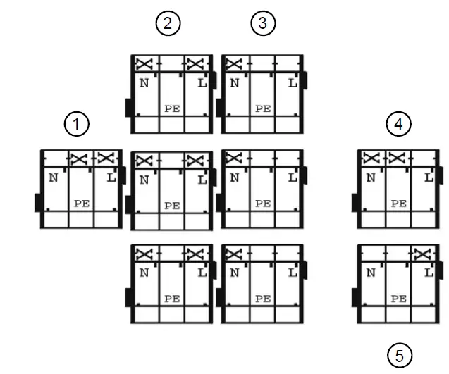
Fig. 9 Rear view of the panel 302 – terminal assignment
Key
- 1 x Boiler
- 3 x Shower
- 3 x Kitchen
- AC mains for land connection
- Mains socket
NOTE:
The protective earth conductor (PE) must be attached to the middle pin