
Amper UPP-2400N-O Portable Power Station
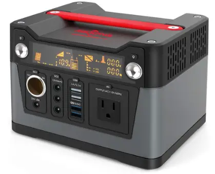
UPP-2400N-O
General Description
This product is a high-end fashion off-grid portable power station, independently developed by Shenzhen Kerui Power Storage Technology Co., Ltd. Light and portable, stylish and generous, using automotive-grade LiFePO4 battery, safe, reliable, and durable; providing 11 0V /12V /SV AC and DC output, suitable for various equipment such as aerial drones, portable ventilators, medical equipment, mobile phones, tablets, laptops, desktop computers, small printers, various lamps, small fish tanks, photographic equipment, electric balance wheelbarrows, etc. It’ s convenient for users to use at home, travel, outdoor work, camping picnics, mountaineering adventures, etc.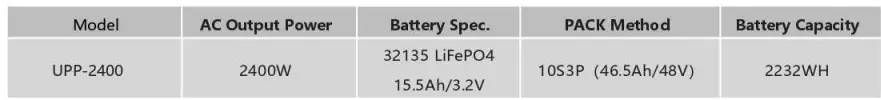
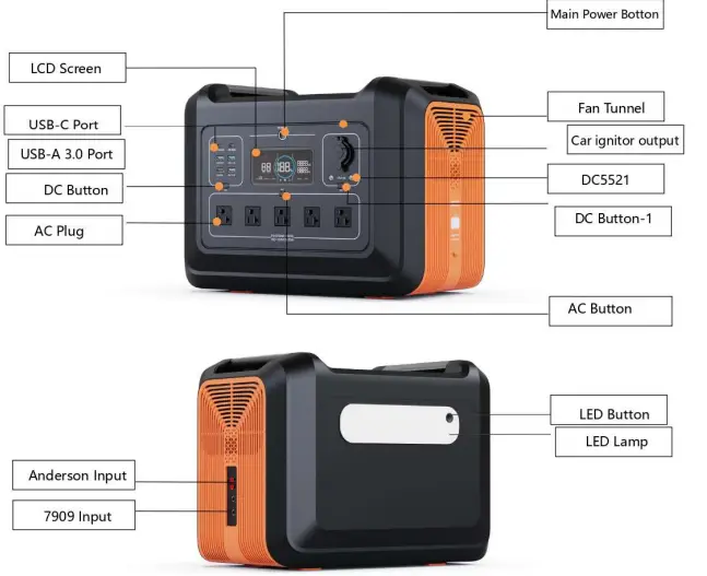
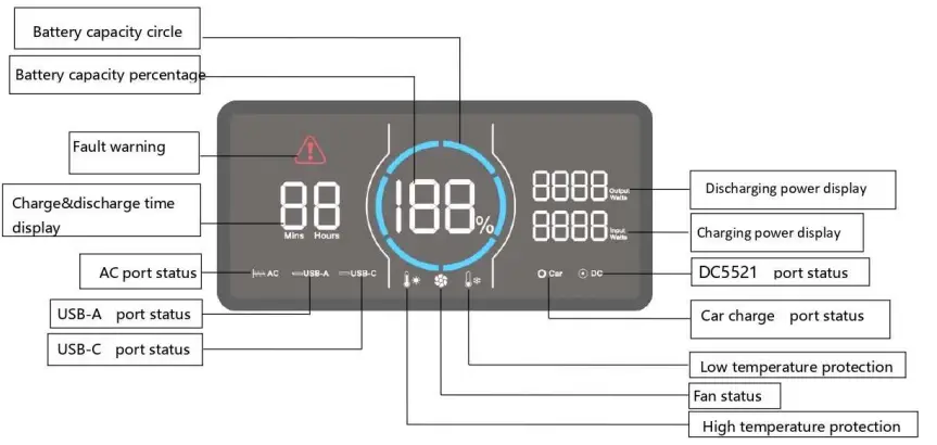
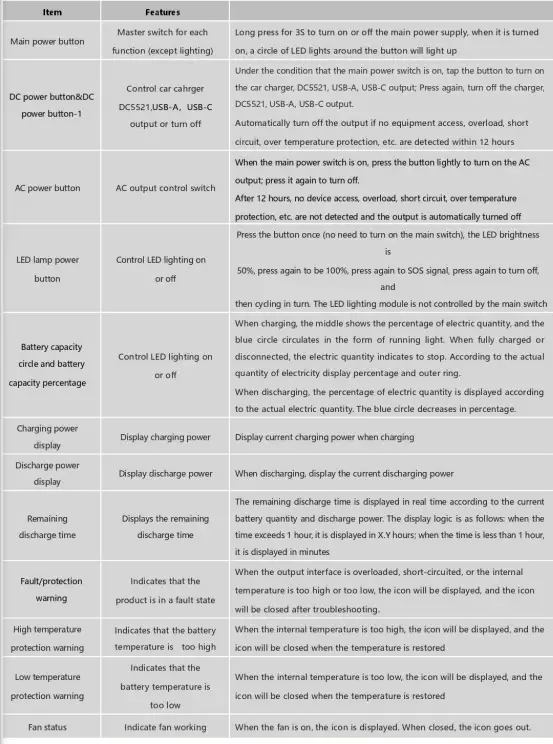
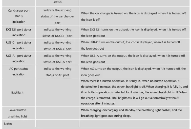
Control and display

DC Input Characteristics
| Paramete r | Symbol | Unit | Typica l | Remarks | |
| Inp ut range | voltage | Vin | Vdc | 12 ~4 5 | The product is equipped with a standard 24V/ 8.3a cha rge r, int e llige nt ide nt ificatio n of MPPT, photovo lt a ic pane l input ca n support the maxim um open circuit voltage 45V curre nt 12A, two inde pe nde nt MPPT |
| Input range | curre nt | lin | A | 0~8.3 | |
| Ada pte r charging t ime | I | Ho ur | 5~7 | 2 chargers charging | |
| Solar charging time | panel | I | Ho ur | I | The maximu m charging t ime depends on the lig ht intensity and solar panel power |
| Maximum charg ing inte rval time | I | month | I | Store when the re maining power is greater than 50% | |
| Input port | I | I | I | DC7909 fe male e n d , m idd le and inne r r ing are positive, outer ring is | |
| Negative Two independent Anderson interfaces, the Anderson interface and DC7909 are in parallel |
DC Output Characteristics
Car Charger Output Characteristics
| Parameter | Symbol | Unit | Typica l | Remarks |
| Output voltage range | Vo | Vdc | 12 | |
| Output current range | lo | A | 10 | |
|
Overload protection |
I |
A |
11 | When the output current exceeds this current lim it, the output will be turned off. After the overload is released, the output must be restored by pressing the DC switch manually. |
| Short circuit protection |
I |
I |
I | If the output te rmina l, wire or external dev ice is sho rt-circuited, the output port will stop output. When short-circuit is removed, you need to manually press the DC switch to restore the output. |
| Output port | I | I | I | One ciga rett e lig ht e r output |
DC5521 Output Characteristics
| Parameter | Symbol | Unit | Typical | Remarks |
| Output voltage range | Vo | Vdc | 12 | |
| Output cur rent range | lo | A | 10 | Two DCs (5521) are output in parallel, a nd the tot a l current with the car charger (cigarette lig ht e r) is less th a n 1OA. |
|
Overload protection |
I |
A |
11 | When the output current exceeds this current lim it, the output will be turned off. After t he ove rload is released, the output must be restored by pressing the DC sw itch manually. |
| Short circu it protection |
I |
I |
I | If the output terminal, wire or exte rna l dev ice is sho rt – c ircuite d, the output port will stop output. When sho rt-circuit is removed, you need to manually press the DC switch to restore the output. |
| Output port | I | I | I | Two DC5521 pa ra lle l outputs |
USB-A Output Characteristics
| Parameter | Symbol | Unit | Typical | Remarks |
| Output voltage range |
Vo |
Vdc | 5.0 | The d efa ult output is 5V, the QC prot oco l is auto mat ical ly recog nized, and o ut putcorres pond ing vo ltag e,, QC3.0/ QC2.0, FCP, SCP, AFC, MTKPE+2.0/1.1, App le2.4 A |
| 9.0 | ||||
| 12.0 | ||||
| Output current range |
lo |
A | 3 | @5.0V |
| 2 | @9.0V | |||
| 1.5 | @12.0V | |||
| Overload protection |
I | w |
18 | When the output power exceeds the maximum power, the output will be turned off. After the over-power state is released, you need to manually press the USB sw itch to restore the output. |
| Short circuit protection |
I |
I |
I | When the output terminal, wire or external device is sho rt-circuited, the output port will stop output. Whe n sho rt-circuit is removed, you need to manually press the USB switch to restore the output. |
| Output port | I | I | I | Two USB-A in depe nde nt outputs |
USB-C (PD60W) Output Characteristics
| Para mete r | Symbol | Unit | Typical | Rema rks |
|
Output voltage range |
Vo |
Vdc | 5.0 |
Auto matica lly recognize the PD protocol and out put the corresponding voltag e . PD3.0, PD2.0, QC3.0, QC2.0, FCP, SCP, AFC, MTKPE+2.0/1.1, App le2.4 A, |
| 9.0 | ||||
| 12.0 | ||||
| 15.0 | ||||
| 20.0 | ||||
| Output current range | lo | A | 3 | |
| Overload protection | I | A | 3.3A | If the output current exceeds this current limit point, the output will be turned off. After the over current is released, re-plug the device to restore the output. |
| Short circuit protection |
I |
I |
I | If the output te rminal, wire or external device is s hort-circuited, the output port will stop output. When sho rt-circuit is re moved, re- plug the dev ice to resume output. |
AC Output Characteristics
| Parameter | Symbol | Un it | Typical | Remarks |
| Output voltage range | Vo | Vac | 110 | |
| Output power | Po | w | 2400 | |
| Peak output powe | w | 5000 | Duration ;£200mS | |
| Output AC frequency | F | Hz | 60 | 50HZ/60HZ can be set |
| Output AC waveform | I | I | I | Sine wave |
| Overload protection | I | w | 100%~1 10% | If the output current e xcee ds the cur rent limit for 1 min , the o ut put will be shut down. After the over cu rrent is removed, manually press the AC switch to restore the output |
| Overload protection 2 |
I | w | 110%~1 35% | If the output current exceeds the current limit for 20 seconds, the output will be shut down. After the over current is removed, manually press the AC switch to restore the output |
| Short circuit protection |
I |
I |
I | If the output terminal, wire or external device is sho rt-circuite d , the output port will stop output. When sho rt-circuit is removed, you need to manually press the AC switch to restore the output. |
| Output port | I | I | I | AC 2 PI NAm e ric a n so c ke t, 3 pa ra lle l o ut put |
LED Lighting Output Characteristics
| Parameter | Symbol | Unit | Min. | Typical | Max. | Remarks |
| Output power | I | w | 3.5 | 5 | 8 | I |
| Luminous flux | I | Im | I | 700 | I | I |
| Color temperature | CCT | K | 3850 | 4000 | 4150 | I |
| CRI | CRI | 80 | I | I | I |
Battery Pack Parameters
| Cell model | I | I | I | I | I | 32135 LiFePO4 |
| PACK Way | I | I | I | I | I | 15 series 3 parallel |
| Voltage | I | Vdc | I | 48 | I | I |
| Battery capacity | I | Ah | I | 46.5 | I | I |
System Protection Function
| Item | Symbol | Unit | Typical | Remarks | ||||
| Battery and voltage protection | Vo | Vdc | 40.5 | |||||
| Battery overvoltage protection | Vo | Vdc | 55.5 | |||||
| High-temperature protection for charging | I | oc | 60 | |||||
| The high-temperature protection of charging restored | I | oc | 55 | |||||
| Charge low temperature protection | I | oc | -10 | |||||
| Charge low-temperature protection restored | I | oc | 0 | |||||
| Discharge high-temperature protection | I | oc | 65 | |||||
| Discharge high temperature protectio n restored | I | oc | 55 | |||||
| Discharge low temperature protection | I | oc | -20 | |||||
| Discharge lo w temperature protection restored | I | oc | -10 | |||||
| Overload protection | I | w | I | See ove rload protect io n for ports | ||||
| Short circuit protection | I | I | I | See ports | short | circuit | protection | for |
|
Total power protect io n |
I | w |
2600 | DC o ut put is prefe rred when the AC and DC are lo a ded at the same t ime. If the AC load exceeds 2600VA, the AC is disconnected. | ||||
Environmental Requirements
| Parameter | Symbol | Unit | Min. | Typical | Max. | Remarks |
| Working temperature (ambient temperature) | oc | 0 | 25 | 40 | ||
| Working humidity | 10% | — | 90% |
| Storage temperature | oc | -20 | 25 | 65 | ||
| Storage humid ity | 5% | — | 95% | |||
| Altitude | m | -50 | — | 3000 | ||
| Cooling method | Fan forced coo ling | |||||
Other Characteristics
| Paramete r | Symbo l | Unit | M in. I Typ i ca l I Max. | Rem arks |
| The life t ime | Lf | year | 3 | |
| Mean inte rval failure time estimation | MTBF | hours | 200000 | Ta 25°C (M IL- HDBK- 217 F) |
| Weight | N.W | g | I 20700 I | |
| Dime ns io n |
DIM . | mm (inch) | L*W * H 16.5*10.6*12 .3 in (420*270*313 mm ) |
Remarks: Unless otherwise specified, all the above parameters are measured under the fully loaded state of the product and at 25°C.
Safety Regulation
| Certificat io n Safety | Safety standar d | Status | Remarks |
| UL | UL2743 | pe nd ing |
Electromagnetic Compatibility
| EM I/ EMS Item | Standa rd | Criterio n |
| Conduct io n CE | FCC part 15 | Class B |
| Rad iatio n RE | FCC part 15 | Class B |
Safety Test Projects
| Safety test | Technical requirement | Remarks |
| Surge | 1500Vac/5mA/60S | AC output-ground, no breakdown, no arcing |
| Insulation resistance | 2100Mohm | AC output to ground, test voltage 500Vdc |
| Leakage current | 0.75mA | 110Vac |
Fault code
| Fault code | Fault info rmat io n | Status | Remarks |
| EO0 | AC short circuit protection | AC+ Red Warning icon blinking, no output is dis p layed | You need to manually press the AC power button to recover |
| E01 | Output overload protect io n | AC and DC ICONS plus red warning ICONS blink, and no output is displayed | The function icon represents where to overload. The overload protection needs to be manually restored |
| E02 | Battery low voltage protection | The function icon blinks, and the corresponding port has no output | After protection, restart corresponding function keys to restore functions |
|
E03 | System overload when AC and DC are used at the same time |
The AC icon blinks, and the AC has no output | When the system concurrently uses more than 2000W, turn off the AC output or reduce the AC load to ensure that the DC output power supply is preferred |
|
E04 |
Inverter fault | AC+ Red Warning icon blinking, no output is displayed | The inverter voltage is too high or too low . The load current IS abnormal. Hardware sampling bias is abnormal |
|
E05 |
BMSfault | The red warning icon blinks. Each function icon cannot be on, and no output IS generated for each function | The communication between the charge protection board fails, and the battery temperature is too high |
Accessories List
| No. | Accessory name | Quantity | Remarks |
| 1 | UPP-2400N-O | 1 | |
| 2 | Adapter 24V/8.3A | 2 | |
| 3 | Car charger to DC7909 charging cable | 1 | |
| 4 | User manual | 1 | |
| 5 | Warra nty card | 1 |


