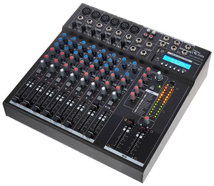
thomann Xmix 1202 FXMP USB Mixer
Musikhaus Thomann
Thomann GmbH
Hans-Thomann-Straße 1
96138 Burgebrach
Germany
Telephone: +49 (0) 9546 9223-0
E-mail: [email protected]
Internet: www.thomann.de
04.08.2021, ID: 422795 (V3)
General information
This user manual contains important information on the safe operation of the device. Read and follow all safety notes and all instructions. Save this manual for future reference. Make sure that it is available to all persons using this device. If you sell the device to another user, be sure that they also receive this manual.
Our products and user manuals are subject to a process of continuous development. We therefore reserve the right to make changes without notice. Please refer to the latest version of the user manual which is ready for download under www.thomann.de.
Further information
On our website (www.thomann.de) you will find lots of further information and details on the following points:
| Download | This manual is also available as PDF file for you to download. |
| Keyword search | Use the search function in the electronic version to find the topics of interest for you quickly. |
| Online guides | Our online guides provide detailed information on technical basics and terms. |
| Personal consultation | For personal consultation please contact our technical hotline. |
| Service | If you have any problems with the device the customer service will gladly assist you. |
Notational conventions
This manual uses the following notational conventions
Letterings
The letterings for connectors and controls are marked by square brackets and italics.
Examples: [VOLUME] control, [Mono] button.
Symbols and signal words
In this section you will find an overview of the meaning of symbols and signal words that are used in this manual.
| Signal word | Meaning |
| DANGER! | This combination of symbol and signal word indicates an immediate dangerous situation that will result in death or serious injury if it is not avoided. |
| CAUTION! | This combination of symbol and signal word indicates a possible dangerous situation that can result in minor injury if it is not avoided. |
| NOTICE! | This combination of symbol and signal word indicates a possible dangerous situation that can result in mate‐ rial and environmental damage if it is not avoided. |
| Warning signs | Type of danger |
 | Warning – high-voltage. |
 | Warning – danger zone. |
Safety instructions
Intended use
This device is intended to be used for amplification, mixing and playback of signals from musical instruments and microphones. Use the device only as described in this user manual. Any other use or use under other operating conditions is considered to be improper and may result in personal injury or property damage. No liability will be assumed for damages resulting from improper use.
This device may be used only by persons with sufficient physical, sensorial, and intellectual abilities and having corresponding knowledge and experience. Other persons may use this device only if they are supervised or instructed by a person who is responsible for their safety.
Safety
DANGER
Danger for children
Ensure that plastic bags, packaging, etc. are disposed of properly and are not within reach of babies and young children. Choking hazard! Ensure that children do not detach any small parts (e.g. knobs or the like) from the unit. They could swallow the pieces and choke! Never let children unattended use electrical devices.
- Electric shock caused by high voltages inside
Within the device there are areas where high voltages may be present. Never remove any covers. There are no user-serviceable parts inside. Do not use the device if covers, protectors or optical components are missing or damaged. - Electric shock caused by short-circuit
Always use proper ready-made insulated mains cabling (power cord) with a protective contact plug. Do not modify the mains cable or the plug. Failure to do so could result in electric shock/death or fire. If in doubt, seek advice from a registered electrician. - CAUTION
Possible hearing damage
With loudspeakers or headphones connected, the device can produce volume levels that may cause temporary or permanent hearing impairment. Do not operate the device permanently at a high volume level. Decrease the volume level immediately if you experience ringing in your ears or hearing impairment. - NOTICE
Risk of fire
Do not block areas of ventilation. Do not install the device near any direct heat source. Keep the device away from naked flames. - Operating conditions
This device has been designed for indoor use only. To prevent damage, never expose the device to any liquid or moisture. Avoid direct sunlight, heavy dirt, and strong vibrations. Only operate the device within the ambient conditions specified in the chapter ‘Technical specifications’ of this user manual. Avoid heavy temperature fluctuations and do not switch the device on immediately after it was exposed to temperature fluctuations (for example after transport at low outside temperatures). Dust and dirt inside can damage the unit. When operated in harmful ambient conditions (dust, smoke, nicotine, fog, etc.), the unit should be maintained by qualified service personnel at regular intervals to prevent overheating and other malfunction. - Power supply
Before connecting the device, ensure that the input voltage (AC outlet) matches the voltage rating of the device and that the AC outlet is protected by a residual current circuit breaker. Failure to do so could result in damage to the device and possibly injure the user. Unplug the device before electrical storms occur and when it is unused for long periods of time to reduce the risk of electric shock or fire. - NOTICE
Danger of short circuit
Switching on phantom power will damage the device if unbalanced XLR cables are connected. Only turn on phantom power when exclusively balanced XLR cables are connected. - Possible damage due to installation of a wrong fuse
The use of different types of fuses can cause serious damage to the unit. Fire hazard! Only fuses of the same type may be used.
Features
- 10-channel mixer with built-in FX processor and USB port
- Bluetooth for wireless data transmission
- 6 mono channels (MIC, line) with 3-band EQ and low cut
- 2 stereo channels with balance control
- 1 × AUX control per channel, PRE/POST selectable
- Master output L/R via 2 × XLR and 2 × 1/4″ phone socket (stereo)
- Headphones output, 1/4″ phone socket (stereo)
- Headphones adjustable together with CTRL room out
- 1 × stereo RCA input
- 1 × stereo RCA output
- 48 V phantom power, globally switchable
- Built-in power supply
Installation and starting up
Unpack and check carefully there is no transportation damage before using the unit.
Keep the equipment packaging. To fully protect the product against vibration, dust and moisture during transportation or storage use the original packaging or your own packaging material suitable for transport or storage, respectively.
Before connecting the operating voltage and before connecting or disconnecting audio cables, set all volume controls of the unit to zero to avoid damage to the connected speakers and devices.
NOTICE!
Possible staining
The plasticiser contained in the rubber feet of this product may possibly react with the coating of your parquet, linoleum, laminate or PVC floor and after some time cause permanent dark stains. In case of doubt, do not put the rubber feet directly on the floor, but use felt-pad floor protectors or a carpet.
Connections and controls
Mono channel strip
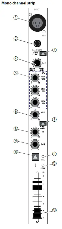
| 1 | [MIC] Balanced XLR mono input to connect a microphone. |
| 2 | [LINE] 1/4″ phone input to connect a line level audio source (keyboards, drum modules etc., balanced or unbalanced). |
| 3
4 | [80 Hz HPF] High pass filter to attenuate rumble noise and other low frequency interfer‐ ence. [GAIN] Rotary control to adjust the input level. |
| 5 | [EQ] 3-band EQ for treble [HIGH], mids [MID] and bass [LOW]. |
| 6 | [AUX] |
| Rotary control to adjust the signal portion to be sent to the [AUX SEND] | |
| output to e.g. create a monitor mix. | |
| 7 | [PRE / POST] |
| When this switch is pressed, the signal portion set with the [AUX] control is | |
| not affected by the channel fader ([PRE]). When the switch is not pressed, | |
| the AUX signal is not subject to the channel fader ([POST]). | |
| 8 | [FX] |
| Rotary control to adjust the signal portion to be sent to the [FX SEND] | |
| output. | |
| 9 | [PAN] |
| Rotary control to arrange the channel signal within the stereo panorama R / | |
| L. | |
| 10 | [PFL] switch |
| With this switch pressed, the channel signal is unaffectedly by the setting of | |
| the channel fader and the internal effects section and present at the outputs | |
| [PHONES] and [CR OUT] to adapt the values). The switch does not affect the | |
| signal at the outputs [MAIN OUTPUT] and [REC OUT]. | |
| 11 | [PFL] LED |
| This LED lights on activated PFL function. | |
| 12 | [PEAK] |
| The LED lights up on channel overload. If this happens, turn the [GAIN] con‐ | |
| trol to the left until this LED is extinguished. | |
| 13 | The channel fader sets the strength of the channel signal in the overall signal. |
Stereo channel strip
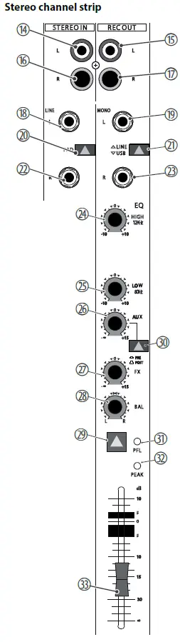
| 14,16 | [STEREO IN] RCA sockets for connecting stereo sources. |
| 15,17 | [REC OUT] Line outputs with RCA sockets for connecting recording devices. |
| 18,19 | [L] |
| 1/4″ phone input to connect the left signal of a stereo line level audio | |
| source (keyboards, drum modules etc.). | |
| With mono signals in the REC OUT channel, use this input with the [R] | |
| socket unused so the signal is present at both sum channels. | |
| 20 | [PAD] |
| Switch for lowering the input sensitivity with particularly powerful signals. | |
| 21 | [LINE | USB] Switch for selecting the analogue line input R / L or the USB input. |
| 22, 23 | [R] 1/4″ phone input to connect the right signal of a stereo line level audio source (keyboards, drum modules etc.). |
| 24,25 | [EQ], [LOW] |
| 2-band EQ for treble [HIGH] and bass [LOW]. | |
| 26 | [AUX] |
| Rotary control to adjust the signal portion to be sent to the [AUX SEND] | |
| output to e.g. create a monitor mix. | |
| 27 | [FX] Rotary control to adjust the signal portion, which is sent to the [FX SEND] output. |
| 28 | [BAL] |
| Rotary control to arrange the channel signal within the stereo balance. | |
| 29 | [PFL] switch |
| With this switch pressed, the channel signal is unaffectedly by the setting | |
| of the channel fader and the internal effects section and present at the out‐ | |
| puts [PHONES] and [CR OUT] to adapt the values). The switch does not | |
| affect the signal at the outputs [MAIN OUTPUT] and [REC OUT]. | |
| 30 | [PRE / POST] |
| When this switch is pressed, the signal portion set with the [AUX] control is | |
| not affected by the channel fader ([PRE]). When the switch is not pressed, | |
| the AUX signal is not subject to the channel fader ([POST]). | |
| 31 | [PFL] LED |
| This LED lights on activated PFL function. |
| 32 | [PEAK] The LED lights up on channel overload. If this happens in the STEREO IN channel press the [PAD] switch. When overload occurs in the REC OUT channel reduce the output level of the signal source connected here. |
| 33 | The channel fader sets the strength of the channel signal in the overall signal. |
Effects section, AUX
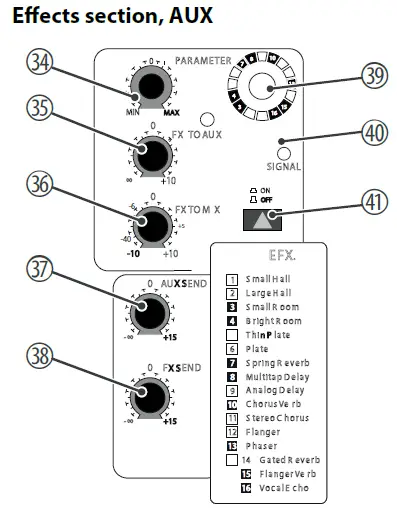
| 34 | [PARAMETER] Rotary control to set the main parameter of the currently selected effect. |
| 35 | [FX TO AUX] Rotary control to adjust the effects portion present at the output [ AUX SEND] . |
| 36 | [FX TO MIX] Rotary control to adjust the effects portion in the overall signal. |
| 37 | [AUX SEND] Rotary control to adjust the overall level at the [ AUX SEND]output. |
| 38 | [FX SEND] Rotary control to adjust the overall level at the [ FX SEND]output. |
| 39 | [1 – 16] Rotary control to select the desired effect, see list [ EFX.] printed beneath the ‘ON | OFF’ switch. |
| 40 | [SIGNAL] When this LED lights up a signal is present at the input of the effect section. |
| 41 | [ON | OFF] Button to turn the effects function on or off. |
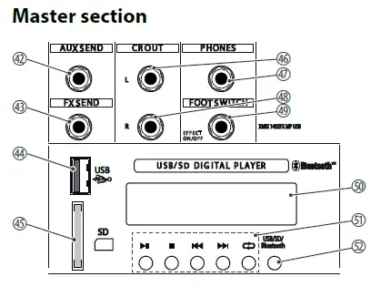
Master section
NOTICE
Possible damages when connecting smartphones or tablets The USB port of the device is only suitable for connecting USB storage media.
Connecting smartphones or tablets causes irreparable damages.
| 42 | [AUX SEND] At this line level output the signal set with the [ AUX]channel controls is present, maybe to create a monitor mix. | ||
| 43 | [FX SEND] At this line level output the signal set with the [ FX]channel controls is present, maybe to be sent to an external effects device. | ||
| 44 | [USB] USB port for playback of digital audio signals. | ||
| 45 | [SD] SD card slot port for playback of digital audio signals. | ||
| 46 | [CR OUT L] Control room output for connecting amplifiers or active speakers. | ||
| 47 | [PHONES] Stereo headphones output. | ||
| 48 | [CR OUT R] Control room output for connecting amplifiers or active speakers. | ||
| 49 | [FOOT SWITCH EFFECT ON/OFF] Connector for a foot switch to turn the internal effects section on or off. | ||
| 50 | DISPLAY This display shows the contents of a connected MP3 player. | ||
| 51 | OPERATING ELEMENTS | ||
| Play / Pause | |||
| Stop | |||
| Skip back | |||
| Skip forward | |||
| Playback function | |||
| Random | random playback | ||
| Repeat one | Infinite loop, selected track | ||
| Repeat folder | Infinite loop, folder content | ||
| Repeat all | Infinite loop, all tracks | ||
| 52 | [USB/SD/Bluetooth] This button can be used to switch between USB, SD or Bluetooth modes. | ||
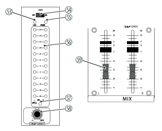
| 53
54
55 | [+48V] LED This LED is lit when the phantom power is on. [+48V] switch When this switch is in ON position, a phantom voltage of 48 V is present at the XLR sockets in the mono channels for using condenser mics. If no con‐ denser mics are used, the switch should be in the OFF position. The phantom voltage must not be switched on if an unbalanced XLR cable is connected to one of the MIC inputs. [POWER] This LED shows that the unit is turned on. |
| 56 | [LEDs] These LED chains indicate the level of the sum signal. Keep the level within a range below +18. The red LEDs indicates overload. In this case, pull back the two master faders so that the red LEDs do not light up any more. If the PFL button is pressed in one of the channels, the signal in this channel is displayed in the left LED chain, regardless of the channel fader. |
| 57 | [PFL] This LED lights up when in at least one of the channels the [ PFL]button is pressed and thus the LED chains do not display the sum signal. |
| 58 | [CR & PHONES] Rotary control to adjust the level at the outputs [CR OUT] and [ PHONES]. |
| 59 | [L MIX R] Master fader to adjust the sum level at the outputs [MAIN OUTPUT], [CR OUT] and [ PHONES]. |
Rear panel
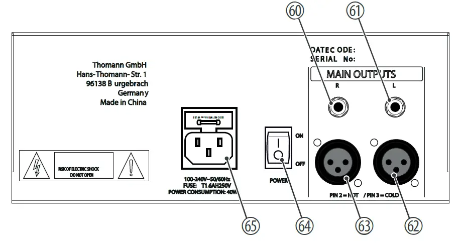
| 60, 61 | [MAIN OUTPUTS] Balanced 1/4″ phone outputs for connecting power amplifiers, effects or recording devices. |
| 62, 63 | [MAIN OUTPUTS] Balanced XLR outputs for connecting power amplifiers, effects or recording devices. |
| 64 | [POWER] Mains switch to turn the device on or off. |
| 65 | [SIGNAL] IEC chassis plug for mains connection with fuse holder. |
Connection pattern – club gig
| Input connections | Voltage supply | IEC chassis plug C14 | |
| Microphone input | Type | XLR chassis socket, 3-pin, balanced | |
| Level | + 4 dBu ± 1 dBu max. | ||
| Impedance | balanced: 6 kΩ unbalanced 3 kΩ ±200 Ω | ||
| Line input | Type | ¼-inch (6.35-mm) jack socket, balanced or unbalanced | |
| Level | + 21 dBu ± 1 dBu max. | ||
| Impedance | balanced: 44 kΩ unbalanced 22 kΩ ±2 kΩ | ||
| Stereo input | Type | 2 × RCA sockets | |
| Level | +21 dBu ± 1 dBu max. | ||
| Impedance | balanced: 44 kΩ, unbalanced: 22 kΩ ±2 kΩ | ||
| Stereo line level input | Type | 4 ×1/4″ jack socket | |
| Level | +21 dBu ± 1 dBu max. | ||
| Impedance | balanced: 44 kΩ, unbalanced: 22 kΩ ±2 kΩ | ||
| Foot switch | 1/4″ phone socket | ||
| USB | USB-A | ||
| Output connections | Master output | Type | 2 ×1/4″ jack socket |
| Level | +26 dBu ± 1 dBu | ||
| Impedance | 100 Ω | ||
| Master output | Type | 2 × XLR panel socket, 3-pin | |
| Level | +26 dBu ± 1 dBu | ||
| Impedance | 100 Ω | ||
| Line output | Type | 2 × RCA sockets | |
| Level | +26 dBu ± 1 dBu max. | ||
| Impedance | balanced: 100 Ω, unbalanced: 200 Ω | ||
| Line level output | Type | 2 ×1/4″ jack socket | |
| Level | +21 dBu ± 1 dBu max. | ||
| Impedance | balanced: 100 Ω, unbalanced: 200 Ω | ||
| Control Room output | Type | 2 ×1/4″ jack socket | |
| Level | +26 dBu ± 1 dBu max. | ||
| Impedance | balanced: 100 Ω, unbalanced: 200 Ω | ||
| Stereo headphones output | Type | 1/4″ phone socket | |
| Level | 150 mW ± 5 mW @ 32 Ω | ||
| EQ | Treble | +/- 10 dB, ± 1.5 dB @ 12 kHz shelving | |
| Mids | +/- 10 dB, ± 1.5 dB @ 1 kHz shelving | ||
| Bass | +/- 10 dB ± 1.5 dB @ 80 Hz shelving | ||
| Effects | 2 × hall reverb 2 × room reverb 2 × plate reverb 1 × spring reverb 2 × delay 2 × chorus Flanger Phaser Gated reverb Flanger reverb Vocal echo | ||
| Signal gain mono channel | 44 dB adjustable mic input (–16 ~ –60 dB) Line (–10 dB ~ + 34 dB) | ||
| Frequency range | 20 Hz ~ 20 kHz ± 2 dB | ||
| Signal-to-noise ratio | 128 dB ± 5 dB Mic equivalent intrinsic noise | ||
| 80 dB ± 5 dB residual noise | |||
| Total harmonic distortion (THD) | <0.025% @ +14 dBu ± 0.5 dBu | ||
| Phantom power | 48 V ± 2 V | ||
| Common mode rejection | 63 dB ± 3 dB @ 1 kHz | ||
| Bluetooth® | Frequency of operation | 2402 MHz … 2480 MHz | |
| Max. transmission power | +4 dBm | ||
| Standard | Version 5.0 | ||
| Power consumption | 36 W | ||
| Operating supply voltage | 100 – 240 V , 50/60 Hz | |
| Fuse | 5 mm × 20 mm, 1.6 A, 250 V, slow-blow | |
| Dimensions (W × H × D) | 345 mm× 100 mm× 340 mm | |
| Weight | 4.7 kg | |
| Ambient conditions | Temperature range | 0 °C…40 °C |
| Relative humidity | 20 %…80 %, non-condensing | |
Further information
| Built-in effects unit | Yes |
| 19″ rack-mountable | No |
| Number of microphone channels | 6 |
| Number of stereo inputs | 2 |
| Number of AUX ways | 1 |
| Phantom power | Yes |
| Built-in power supply | No |
| Parametric | No |
| Digital interface | No |
| USB 2.0 | Yes |
| Bluetooth | Optional |
Plug and connection assignment
Introduction
This chapter will help you select the right cables and plugs to connect your valuable equipment in such a way that a perfect sound experience is ensured.
Please note these advices, because especially in ‘Sound & Light’ caution is indicated:
Even if a plug fits into the socket, an incorrect connection may result in a destroyed power amp, a short circuit or ‘just’ in poor transmission quality.
Balanced and unbalanced transmission
Unbalanced transmission is mainly used in semi-professional environment and in hifi use. Instrument cables with two conductors (one core plus shielding) are typical representatives of the unbalanced transmission. One conductor is ground and shielding while the signal is transmitted through the core. Unbalanced transmission is susceptible to electromagnetic interference, especially at low levels, such as microphone signals and when using long cables.
In a professional environment, therefore, the balanced transmission is preferred, because this enables an undisturbed transmission of signals over long distances. In addition to the conductors ‘Ground’ and ‘Signal’, in a balanced transmission a second core is added. This also transfers the signal, but phase-shifted by 180°. Since the interference affects both cores equally, by subtracting the phase-shifted signals, the interfering signal is completely neutralized. The result is a pure signal
without any noise interference.
1/4″ TS phone plug (mono, unbalanced)
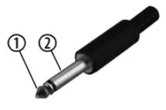
| 1 | Signal |
| 2 | Ground, shielding |
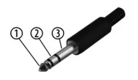
| 1/4″ TRS phone plug (mono, balanced) | |
| 1 | Signal (in phase, +) |
| 2 | Signal (out of phase, –) |
| 3 | Ground |
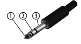
| 1/4″ TRS phone plug (stereo, unbalanced) | |
| 1 | Signal (left) |
| 2 | Signal (right) |
| 3 | Ground |
1/4″ TRS phone plug (mono, balanced)
1/4″ TRS phone plug (stereo, unbalanced)
XLR plug (balanced)
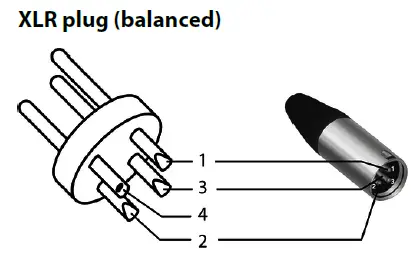
| 1 | Ground, shielding |
| 2 | Signal (in phase, +) |
| 3 | Signal (out of phase, –) |
| 4 | Shielding on plug housing (option) |
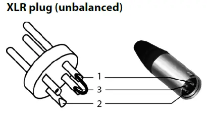
| XLR plug (unbalanced) | |
| 1 | Ground, shielding |
| 2 | Signal |
| 3 | Bridged to pin 1 |
XLR plug (unbalanced)
RCA connection

Drawing and table indicate the pin assignment of an RCA plug.
| 1 | Signal |
| 2 | Ground, shielding |
Protecting the environment
Disposal of the packaging material
For the transport and protective packaging, environmentally friendly materials have been chosen that can be supplied to normal recycling.
Ensure that plastic bags, packaging, etc. are properly disposed of.
Do not just dispose of these materials with your normal household waste, but make sure that they are collected for recycling. Please follow the notes and markings on the packaging.
Disposal of your old device
Dispose of this device through an approved waste disposal firm or through your local waste facility. When discarding the device, comply with the rules and regulations that apply in your country. If in doubt, consult your local waste disposal facility.


