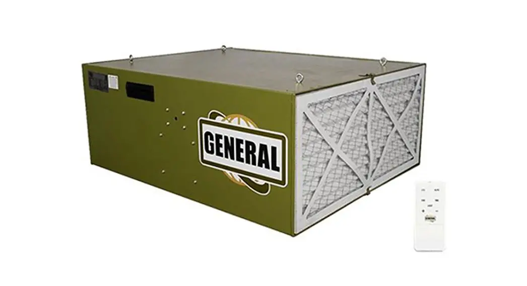
![]() Air Filtration 10-1000
Air Filtration 10-1000
NEW!
MODEL #10-1000 M1
User Manual
SETUP & OPERATION MANUAL
FEATURES
The Patent pending SMART™ Auto Dust Sensor will automatically turn the machine on and off when it senses the dust levels in the air.
Two-Filter System with Air Diffuser disperses outgoing air into a broader pattern Disposable Electrostatic Outer Filter attracts more dust particles than standard filters Inner Pocket Filter is removable for easy cleaning.
Easy Grip Handles allow easy portability of unit Four Eye Bolts let you hang unit from shop ceiling.
Remote Control has built-in timer with a 1-12 hour settings; automatically shuts system off at the end of the time setting.
Fully-Enclosed Ball Bearing Motor with Overload Protection for long, dependable service.
Rubber Feet prevent marring of surface when placed on workbench.
SPECIFICATIONS
| STOCK NUMBER | 10-1000 M1 | FILTER CYCLE (MIN.) | 3.2 |
| OUTER FILTER | 5 MICRONS | CYCLES PER HOUR (20’X20’X8′) | 20.06 cycles |
| INNER FILTER | 1 MICRON | MOTOR | 1/5 HR 115V, 60HZ, 1 PH, 6P 4.5A |
| OVERALL DIMENSIONS (L x W x H) | 30″ x23-7/8″ 11-3/4″(762 x 606 x 300mm) | NET WEIGHT | 63-1/8 LBS(28.65 kgs). |
| SOUND RATING @ 3FT | HIGH SPEED 71 DB MEDIUM SPEED 68 DB LOW SPEED 61 DB | SHIPPING WEIGHT | 69-1/2 LBS(31.5 kgs). |
| AIR FLOW | HIGH SPEED 1068 CFM MEDIUM SPEED 710 CFM LOW SPEED 560 CFM |
![]()
GENERAL INTERNATIONAL POWER PRODUCTS LLC
6243 Industrial Parkway | Whitehouse, Ohio 43571 (USA)
For Your Own Safety
- Read and understand instruction manual before installing or operating air cleaner.
- To reduce the risk of injury disconnect the air cleaner from the power source (unplug) before servicing or changing filters.
- If ceiling mounted, bottom of air cleaner must be at least 7 feet above the floor.
- If ceiling mounted, mounts must be anchored to building structure which will support a minimum of at least 100 pounds. Never mount to surfaces such as dry wall or false ceiling grids, etc.
- To reduce the risk of electrical shock, do not expose air cleaner to water or rain.
- Never duct a machine directly into the air cleaner.
- To avoid a potentially dangerous situation, do not use this equipment to filter flammable vapors or smoke. This air cleaner is designed and intended for the filtration of air borne wood dust only. It is neither designed nor intended for any other purpose whatsoever.
- Failure to comply may result in serious injury and / or property damage.
The above specifications were current at the time this manual was published, but because of our policy of continuous improvement, GENERAL reserves the right to change specifications at any time and without prior notice, without incurring obligations.
Disclaimer:
The information and specifications in this manual pertain to the unit as it was supplied from the factory at the time of printing. Because we are committed to making constant improvements, General” International reserves the right to make changes to components, parts, or features of this unit as deemed necessary, without prior notice and without obligation to install any such changes on previously delivered units. Reasonable care is taken at the factory to ensure that the specifications and information in this manual corresponds with that of the unit with which it was sup-plied. However, special orders and “after factory” modi-fications may render some or all information in this manual inapplicable to your machine. Further, as several gene-rations of this model of air filtration and several versions of this manual may be in circulation, if you own an earlier or later version of this unit, this manual may not depict your air filtration exactly. If you have any doubts or questions contact your retailer or our support line with the model number of your unit for clarification.
WARRANTY STATEMENT AND POLICY
Commercial General™ (Green Line) & Excalibur™ (Black Line) branded products:
3 -YEAR LIMITED WARRANTY All products are warranted for a period of 3 years (36 months) from the date of purchase. General™ agrees to repair or replace any part or component which upon examination, proves to be defective in either workmanship or material or parts and labor to the original purchaser during this 3-year warranty period, subject to the “conditions and exceptions” as listed below. Repairs made without the written consent of General will void the warranty
EXTEND YOUR WARRANTY:
Register your new General™ or Excalibur™ within 60 days of your purchase and get an extended 2 years, for a total of 5 years, of warranty coverage.
Go to www.general.ca/warranty/registration
DISCLAIMER:
Because we are committed to making constant improvements, General™ reserves the right to make changes to components, parts or features of this unit as deemed necessary, without prior notice and without obligation to install any such changes on previously delivered units. Reasonable care is taken at the factory to ensure that the specifications and information in this manual corresponds with that of the unit with which it was supplied.
TO FILE A CLAIM:
To file a claim under our Standard 3 -year Limited Warranty, ail defective parts, components or machinery must be returned freight or postage prepaid to General™, or to a nearby distributor, repair center or other location designated by General™. For further details call our service department at 1-844-877-5234 or [email protected] Along with the return of the product being claimed for warranty, a copy of the original proof of purchase and a “letter of claim” must be included (a warranty claim form can also be used and can be obtained, upon request, from General™ or an authorized distributor) clearly stating the model and serial number of the unit (if applicable) and including an explanation of the complaint or presumed defect in material or workmanship.
CONDITIONS AND EXCEPTIONS:
This coverage is extended to the original purchaser only. Prior warranty registration is not required but documented proof of purchase, i.e. a copy of original sales invoice or receipt showing the date and location of the purchase as well as the purchase price paid, must be provided at the time of claim.
Warranty does not include failures, breakage or defects deemed after inspection by General™ to have been directly or indirectly caused by or resulting from; improper use, or lack of or improper maintenance, misuse or abuse, negligence, accidents, damage in handling or transport, or normal wear and tear of any generally considered consumable parts or components. Repairs made without the written consent of General™ will void all warranty. This five-year warranty does not cover products used for commercial, industrial or educational purposes. The warranty term for these claims will be limited to a two-year period.
GENERAL sells through distributors only. The specifications listed in GENERAL printed materials and on official GENERAL website are given as general information and are not binding. GENERAL reserves the right to effect at any time, without prior notice, those alterations to parts, fittings, and accessory equipment which they may deem necessary for any reason whatsoever.
IMPORTANT SAFETY
WARMING – To reduce risk of injury
- FOR YOUR OWN SAFETY, READ INSTRUCTION MANUAL BEFORE OPERATING THE TOOL. Learn the tool’s application and limitations as well as the specific hazards peculiar to it.
- KEEP GUARDS IN PLACE and in working order.
- ALWAYS WEAR EYE PROTECTION.
- GROUND ALL TOOLS. If tool is equipped with three prong plug, It should be plugged into a three-hole electrical receptacle. If an adapter is used to accommodate a two prong receptacle, the adapter lug must be attached to a known ground. Never remove the third prong.
- KEEP WORK AREA CLEAN. Cluttered areas and benches invite accidents.
- DON’T USE IN DANGEROUS ENVIRONMENT. Don’t use power tools in damp or wet locations, or expose them fo rain. Keep work area well-lighted.
- KEEP CHILDREN AND VISITORS AWAY. All children and visitors should be kept a safe distance from work area.
- MAKE WORKSHOP CHILDPROOF. Use padiocks, master switches, or remove starter keys.
- DON’T FORCE TOOL. It will do the job better and be safer at the rate for which it was designed.
- USE RIGHT TOOL. Don’t force tool or attachment to do a job for which it was not designed.
- WEAR PROPER APPAREL. No loose clothing, gloves, neckties, rings, bracelets, or other jewelry to get caught in moving parts. Nonslip footwear Is recommended. Wear protective hair covering to contain long hair.
- ALWAYS USE SAFETY GLASSES. Wear safety glasses (must comply with ANSI 287.1). Everyday eyeglasses only have impact resistant lenses; they are not safety glasses. Also use face or dust mask if cutting operation is dusty.
- SECURE WORK. Use clamps or a vise to hold work when practical. It’s safer than using your hands and frees both hands to operate tool.
- DONT OVERREACH. Keep proper footing and balance at all times.
- MAINTAIN TOOLS IN TOP CONDITION. Keep tools sharp and clean for best and safest performance. Follow instructions for lubricating and changing accessories.
- DISCONNECT TOOLS before servicing and when changing filters.
- USE RECOMMENDED ACCESSORIES. The use of accessories and attachments not fecommended by manufacturer may cause hazards or risk of injury to persons.
- AVOID ACCIDENTAL STARTING. Make sure switch Is in “OFF” position before plugging in power cord.
- NEVER STAND ON TOOL. Serious injury could occur if the tool is tipped or if the fan blade is accidentally contacted.
- CHECK DAMAGED PARTS. Before further use of the tool, a guard or other part that is damaged should be carefully checked to ensure that it will operate properly and perform its Intended function- check for alignment of moving parts, binding of moving parts, breakage of parts, mounting, and any other conditions that may affect its operation. A guard or other part that is damaged should be property repaired or replaced.
- NEVER LEAVE TOOL RUNNING UNATTENDED. TURN POWER OFF. Don’t leave tool until it comes to a complete stop.
- DRUGS, ALCOHOL, MEDICATION. Do not operate tool while under the influence of drugs, alcohol or any medication.
- MAKE SURE TOOL IS DICONNECTED FROM POWER SUPPLY while motor is being mounted, connected or reconnected
WARNING: This product can expose you to chemicals including lead which is known to the State of California to cause cancer and birth defects or other reproductive harm. For more information go to http://www.p65warnings.ca.gov.
WARNING: Drilling, sawing, sanding, or machining wood products generates wood dust and other substances known to the State of California to cause cancer. Avoid inhaling dust generated from wood products or use a dust mask or other safeguards for personal protection. Wood products emit
chemicals known to the State of Callfomia to cause birth defects or other reproductive harm. For more information ao to http://www.p65warninas.ca.gov/wood.
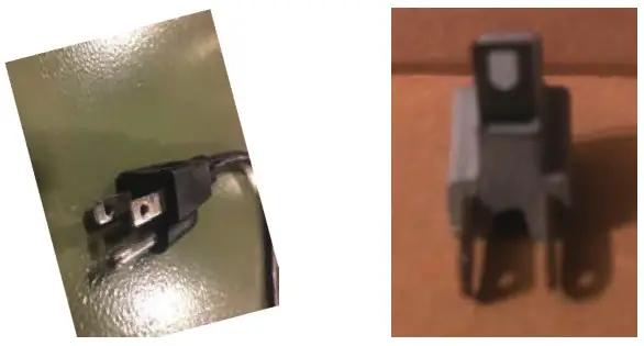
 ELECTRICAL REQUIREMENTS
- In the event of a malfunction or breakdown, grounding provides a path of least resistance for electric current to reduce the risk of electric shock. This tool is equipped with an electric cord having an equipment-grounding conductor and a grounding plug. The plug must be plugged into a matching outlet that is properly installed and grounded in accordance with all local codes and ordinances.
- Do not modify the plug provided. If it will not fit the outlet, have the proper outlet installed by a qualified electrician.
- Improper connection of the equipment-grounding conductor can result in a risk of electric shock. The conductor, with insulation having an outer surface that is green with or without yellow stripes, is the equipment grounding conductor. If repair or replacement of the electric cord or plug is necessary, do not connect the equipment-grounding conductor to a live terminal.
- Check with a qualified electrician or service personnel if the grounding instructions are not completely understood, or if in doubt as to whether the tool is properly grounded.
- Use only three wire extension cords that have three-prong grounding plugs and three-pole receptacles that accept the tool’s plug*.
- Repair or replace a damaged or worn cord immediately.
- This tool is intended for use on a circuit that has an outlet that looks the one illustrated in Figure A below. The tool has a grounding piug that looks like the grounding plug as illustrated in Figure A below. A temporary adapter, which locks like the adapter as illustrated in Figures B below, may be used to connect this plug to a two-pole receptacle, as shown in Figure B if a properly grounded outlet is not available.** The temporary adapter should only be used until a properly grounded outlet can be installed by a qualified electrician. The green-colored tigid ear or tab, extending from the adapter, must be connected to a permanent ground such as a properly grounded outlet box.
 * Canadian electrical codes require extension cords to be certified SJT type or better.
* Use of an adapter in Canada is not acceptable.
 * Canadian electrical codes require extension cords to be certified SJT type or better.
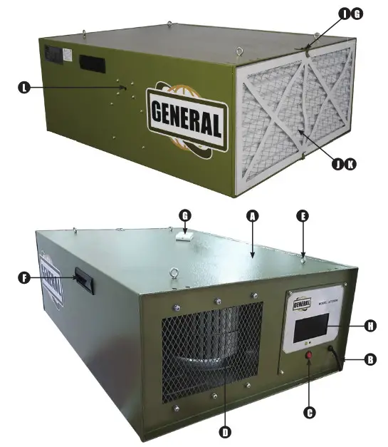
IDENTIFICATION OF MAIN PARTS AND COMPONENTS
| A. BOX | F. GRIP | K. MEDIUM EFFICIENCY FILTER |
| B. POWER CABLE | G. REMOTE CONTROL | L. DUST SENSOR HOLE |
| C. POWER SWITCH | H. COLOUR LCD | M. LED DOWNLIGHT(IN THE BOTTOM) |
| D. DRAUGHT FAN | I. CLIP | |
| E EYEBOLT | J. PRIMARY FILTER |
PRODUCT DESCRIPTION
This powerful unit is perfect for the smaller home shop. Simply hang it from the ceiling plug it in and let it do its thing. With the NEW auto dust sensor, the machine will automatically sense when there is dust in the air and turn itself on. It also senses when the air is clean and will automatically turn itself off.
This NEW machine is so SMART it will clean the air in your shop without you even thinking about it. This unit was the first in the industry with the SMART auto sensor, remote control, timer and three speeds will quickly become the industry standard.
CONTENTS OF SHIPPING CARTON
Air Fittration Unit x 1
Remote Control x 1
AAA Batteries x 2
Eye Bolts and Nuts x 4
Manual and Warranty Card x 1
ASSEMBLY INSTRUCTIONS
![]()
- SERIOUS PERSONAL INJURY COULD OCCUR IF YOU CONNECT THE MACHINE L\ TO THE POWER SOURCE BEFORE YOU HAVE COMPLETED THE SETUP PROCESS. DO NOT HOOK-UP THE MACHINE TO A POWER SOURCE UNTIL INSTRUCTED
TO DO SO. - BE SURE TO READ AND UNDERSTAND THIS ENTIRE MANUAL.
- USE CAUTION AND WEAR GLOVES WHEN HANDLING METAL PARTS, WHICH CAN CUT IF HANDLED CARELESSLY.
- THE SOUND LEVEL OF THIS MACHINE IS RATED AT APPROXIMATELY 61-71 DB DURING OPERATION. MAKE SURE THAT ADEQUATE HEARING PROTECTION IS USED AND THAT THE OVERALL SOUND LEVEL WITHIN THE WORKING
ENVIRONMENT IS TAKEN INTO CONSIDERATION.
TOOLS REQUIRED FOR ASSEMBLY
Cross Point Screwdriver x 2
10mm Wrench x 1
- Remove all packing from inside of the unit by removing the outer filter and inner filters.
- The air filtration unit can be hung from the ceiling. Remove four screws from the cabinet top (Fig. 1).
- Hang the unit using four eyebolts (Fig. 1), and four hex nuts provided.

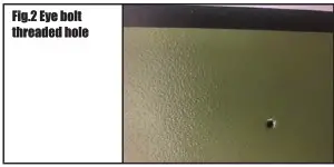
- The lock nut needs to be threaded almost all the way up the eyebolt. Screw the eye bolt into the hole (Fig.2) and tighten tock nut against the cabinet top. You will need to hold the eye bolt so it does not spin while tightening the lock nut.

- Repeat steps for remaining three eyebolts.
NOTE: Make sure chain and ceiling hooks are properly rated for hanging this unit. Hang unit with a sever-foot clearance from the floor to bottom of unit. • Mounts must be anchored to building structure, which will support a minimum of at least 100 pounds. Never mount to surfaces such as dry wall or false ceiling grids, etc.

Remote Control and Features
The remote control is a six-button remote control with a light button as shown in the figure 3.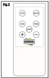 Function of the keys
- The I/O key is the on-off key. Press once to power on and again to power off.
- AUTO is the automatic mode key. Press this button to indicate that the fan and sensor will automatically operate according to the current air quality. For example, if the air quality is not good, the fan will start to work at high speed and high air volume, when the air quality get medium, it
will change to medium air volume and when the air quality is good, the fan stops working. - FAN is the manual air volume adjustment key of the FAN. The air volume is divided into three levels: high, medium and low. After pressing this button, use the + (plus) or – (minus) button to manually adjust the air volume.
- TIME is the timing function key. After pressing this key, use the + (plus) or – (minus) button to adjust the working time (1-12 Hours) + and – keys are parameter adjustment keys.
The above remote control function requires the host LCD screen to display the corresponding changes synchronously during operation. Including timing and time indices display, fan speed change and air quality change display.
MAINTENANCE & SERVICING
REPLACEMENT PARTS
To order parts or reach our service department, call 888-664-0449, Monday through Friday (see our website for business hours, (www.GENERAL.ca). Having the Model Number and Serial Number of your machine available when you call will allow us to serve you quickly and accurately.
CHANGING THE FILTERS.
To reduce the risk of injury, disconnect the air cleaner from the power source (unplug) before servicing or changing filters. Failure to comply may cause serious injury!
There are two filters that need to be changed. The outer filter can easily be removed by disengaging the two clips (fig 4:) Now you can simply pull the fitter out, or use a screwdriver to pop the filter out.
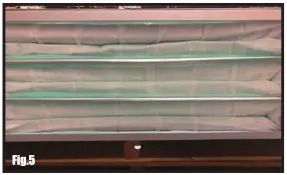
The inner filter (Fig 5.) can now be pulled out of the unit. The inner filter can be blown out with compressed air. The filters should be replaced depending on the amount of usage and the environment of your shop.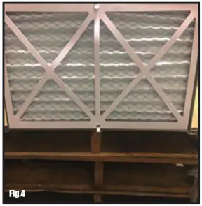
Clogged filters will reduce the amount of air me circulation. There is an arrow indicating the air flow direction on the outer filter. Make sure the filter is inserted facing the proper direction.
OPTIONAL FILTERS
Electrostatic outer fillter
Washable electrostatic outer filter Inner filter
Charcoal filter HEPA filter
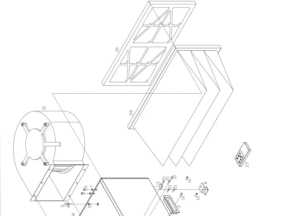
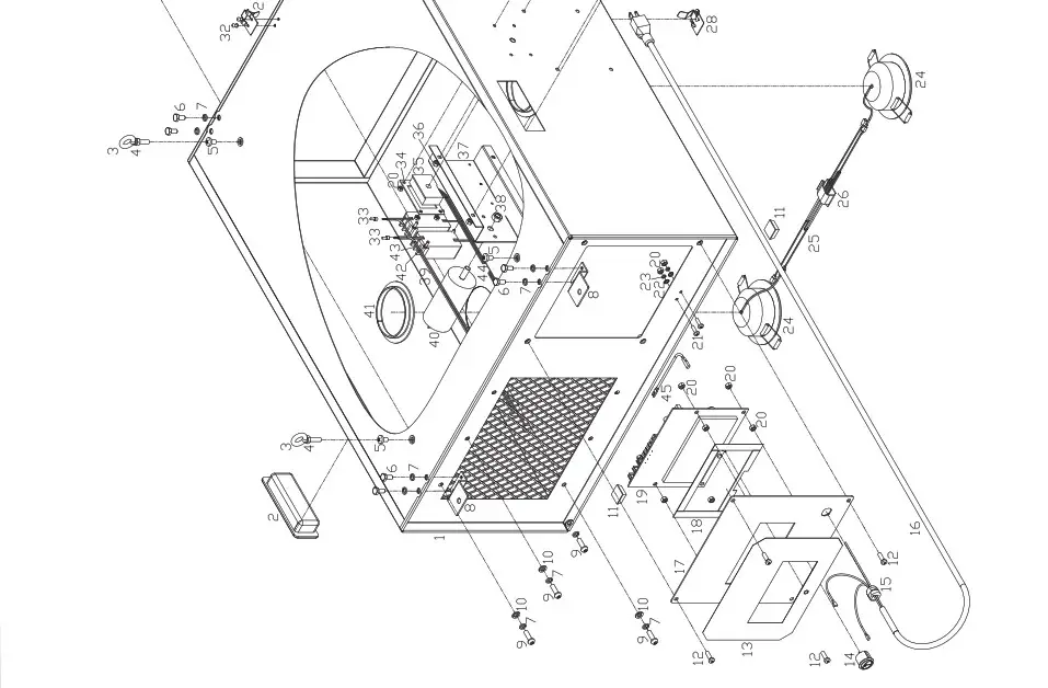
PARTS LIST
10-1000M1
| PARTS | REFERENCE | DESCRIPTION | SPECIFICATION | QTY. |
| 1 | 101000-1 | Box | 1 | |
| 2 | 101000-2 | Grip | 2 | |
| 3 | 101000-3 | Eyebolt | M6x20 | 4 |
| 4 | 101000-4 | Hex nut | GB/T6170/M6 | 4 |
| 5 | 101000-5 | Cross pan head screw | GB/T818/M6 x 10 | 4 |
| 6 | 101000-6 | Hexagon bolt | GB/T5781/M6x8 | 8 |
| 7 | 101000-7 | Spring washer | GB/T93/6 | 14 |
| 8 | 101000-8 | Board | 4 | |
| 9 | 101000-9 | Hexagon socket head screw | GB/T70.2/M6 x20 | 6 |
| 10 | 1 01 000-1 0 | Flat washer | GB/T97.1/6 | 6 |
| 11 | 1 01 000-1 1 | Rubber pad | 4 | |
| 12 | 1 01 000-1 2 | Cross pan head screw | GB/T818/M5 x16 | 8 |
| 13 | 1 01 000-1 3 | Face label | 1 | |
| 14 | 1 01 000-1 4 | Power switch | 10A/125V | 1 |
| 15 | 1 01 000-1 5 | Cable gland | 6N-4 | 1 |
| 16 | 1 01 000-1 6 | Power cable | DLC3KEE9S-A-BPS | 1 |
| 17 | 1 01 000-1 7 | Plate | 1 | |
| 18 | 101000-18 | Foaming strip | 0.44m | |
| 19 | 1 01 000-1 9 | PCB | 1 | |
| 20 | 101000-20 | Hex nut | GB/T6170/M4 | 13 |
| 21 | 101000-21 | Cross pan head screw | GB/T818/M4 x 16 | 6 |
| 22 | 101000-22 | Tooth washer | GB/T862.1 4 | 2 |
| 23 | 101000-23 | Spring washer | GB/T93/4 | 2 |
| 24 | 101000-24 | LED downlight | 5W | 2 |
| 25 | 101000-25 | Wiring | SM2.54 | 1 |
| 26 | 101000-26 | Cable clamp | 3 | |
| 27 | 101000-27 | Remote control | 1 | |
| 28 | 101000-28 | Clip | 2 | |
| 29 | 101000-29 | Medium efficiency filter | 298 x 595 x 22/F9 | 1 |
| 30 | 101000-30 | Primary filter | 1 | |
| 31 | 101000-31 | Draught fan | 120V/60HZ/150W | 1 |
| 32 | 101000-32 | Rebite | GB/T12618/3 x 8 | 4 |
| 33 | 101000-33 | Closed end terminal | CE-1/02.4 | 2 |
| 34 | 101000-34 | Buckle | 1 | |
| 35 | 101000-35 | Dust sensor | PM2.5 | 1 |
| 36 | 101000-36 | Hex nut | GB/T6170/M5 | 4 |
| 37 | 101000-37 | Frame | 1 | |
| 38 | 101000-38 | Hex nut | GB/T6170/M8 | 1 |
| 39 | 101000-39 | Wiring | CH3.96 | 2 |
| 40 | 101000-40 | Capacitor | C61/300VAC5060HZ/12.5uF | 1 |
| 41 | 101000-41 | Foamed strip | 5x25x10 | 0.46m |
| 42 | 101000-42 | Self-tapping screw | GB/T845/ST3.5 x 9.5/F | 4 |
| 43 | 101000-43 | LED driver | AC85-230V/DC9-20V0.3A | 2 |
| 44 | 101000-44 | Wiring | ZH1.5 | 1 |
| 45 | 101000-45 | Cable | DL1EHB-H-B-P | 1 |
DIAGRAMS
WIRING DIAGRAM
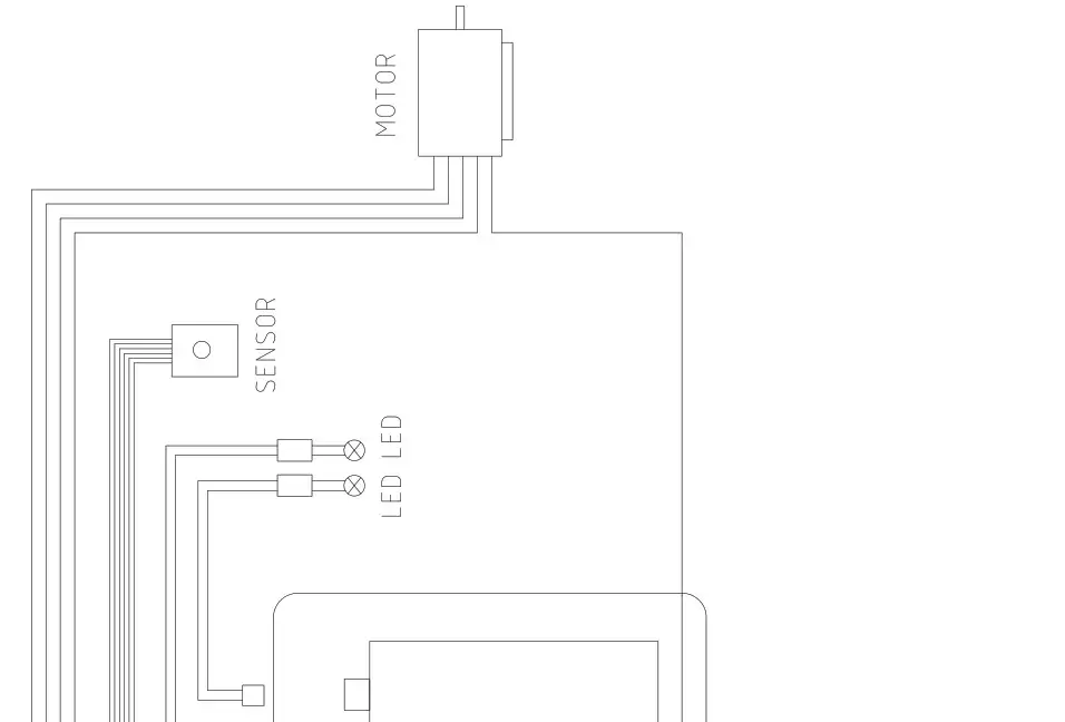
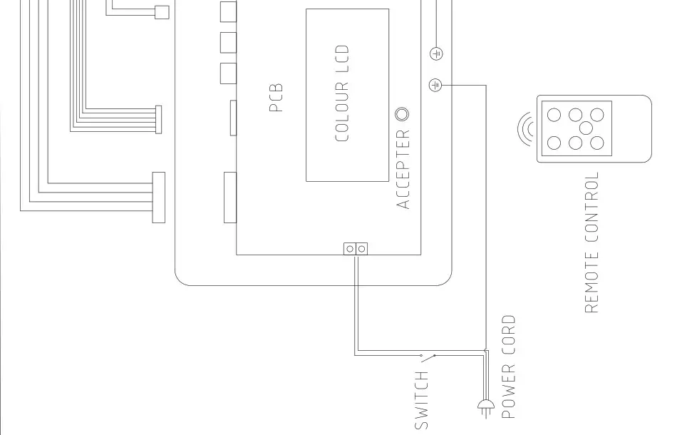 MODEL 10-100 M1
![]()
GENERAL INTERNATIONAL POWER PRODUCTS LLC
6243 Industrial Parkway I Whitehouse, Ohio 43571 (USA)
IMPORTANT
When ordering replacement parts, always give the model number, serial number of the machine and part number. Also a brief description of each item and quantity desired.


