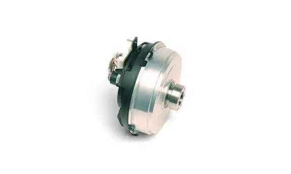
overview OVU20005 Artemis Servotorq Integrated Servo Motor User Guide
Thank you for purchasing Overview’s Artemis Integrated Servo Motor.
To quickly get up and running with your Artemis motor, please refer to the Technical Manual, I²C Protocol Guide and Application Notes located at:
http://www.overview.co.uk/technical-support/
Please observe the following precautions when handling and operating the Artemis motor:

- The Artemis motor uses semiconductors which can be damaged by electrostatic discharge (ESD). The motor must be handled and stored in an ESD safe environment.
- The Artemis motor’s nominal supply is 48V DC, using up to 1 A DC. Do not hot-plug the power supply.
Reference Information
The Artemis I²C control interface uses 12V signalling levels. Please see the Technical Manual for further details and a reference interface circuit.
When initially powered up, the motor will perform an initialisation routine as detailed in the Technical Manual. During initialisation, the unit will slightly rotate and temporarily draw a current less than or equal to the max rated current depending on the inertial load.
Artemis motor pinout reference (please see the Technical Manual for further details):
- Connector type: JST ZPD 24-way. Mating housing part # ZPDR 24V-S, crimp part # SZPD-002T-P0.3
- Mating housing part: https://www.digikey.co.uk/products/en?keywords=%23%20ZPDR-24V-S
- Pre-crimped leads: https://www.digikey.co.uk/product-detail/en/jst-sales-america-inc/SZPD002T-P0-3/455-2539-1-ND/2472595)
Connectors
| Pin | Signal | Pin | Signal |
| 1 | 48Vin | 2 | GND |
| 3 | 48Vin | 4 | GND |
| 5 | 48Vin | 6 | GND |
| 7 | PASS THROUGH PAIR 1+ | 8 | PASS THROUGH PAIR 4+ |
| 9 | PASS THROUGH PAIR 1- | 10 | PASS THROUGH PAIR 4- |
| 11 | PASS THROUGH PAIR 2+ | 12 | PASS THROUGH PAIR 5+ |
| 13 | PASS THROUGH PAIR 2- | 14 | PASS THROUGH PAIR 5- |
| 15 | PASS THROUGH PAIR 3+ | 16 | I 2C SDA |
| 17 | PASS THROUGH PAIR 3- | 18 | I 2C SCL |
| 19 | PASS THROUGH AUX 1 | 20 | I 2C ADDRESS SELECT (Not available via slip-rings) |
| 21 | PASS THROUGH AUX 2 | 22 | NOT CONNECTED |
| 23 | NOT CONNECTED | 24 | BODY (SPINDLE CONNECTION) |
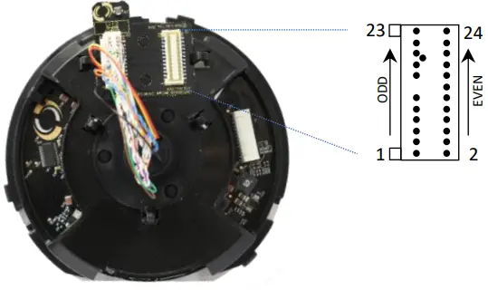
All ZPD connectors have the same pinout (on both PCBAs).
Note: I2C Address Select to be connected to GND for address 0x29, open for 0x28 (7-bit address). This is only available on the connectors on the large circular motor PCBA; this signal is not passed through the slip-rings supplied. (PAN/TILT address can be firmware selected in such cases.)
Overview Limited
Overview House Kingswey Business Park Forsyth Road Woking GU21 5SA United Kingdom
© Overview Ltd 2021
www.overview.co.uk


