![]()
installation Manual and Operating lnstructions


FOREWORD
This manual provides information intended for use by persons who, in accordance with current regulatory requirements, are qualified to install this equipment. If further information is required, please contact:
True Blue Power
c/o Mid-Continent Instrument Co., Inc.
Attn: Customer Service Dept.
9400 E. 34th St. N.
Wichita, KS 67226 USA
Phone 316-630-0101
Fax 316-630-0723
www.truebluepowerusa.com
www.mcico.com
We welcome your comments concerning this manual. Although every effort has been made to keep it free of errors, some may occur. When reporting a specific problem, please describe it briefly and include the manual part number, the paragraph/figure/table number, and the page number. Send your comments to:
True Blue Power
c/o Mid-Continent Instrument Co., Inc.
Attn: Technical Publications
9400 E. 34 th St. N.
Wichita, KS 67226 USA
Phone 316-630-0101
Fax 316-630-0723
http://www.truebluepowerusa.com/pdfs/TA202_InstallationManual.pdf
Download the current version of this installation manual using your smartphone or tablet.
© Copyright 2018
Mid-Continent Instrument Co., Inc.
REVISION HISTORY
| Rev | Date | Detail | Approved |
| A | 03/14/2016 | Initial release. | BAW |
| B | 04/25/2016 | Updated formatting, added AEH statement to table 1.3 | CAS |
| C | 05/10/2016 | Added single port unit mounting options, removed configurations table. | BAW |
| D | 06123/2016 | Added two screws (1/4″) to include a connector kit. | SCH |
| E | 01/04/2017 | Updated to include a new mounting option. Added 1.2.4. | BAW |
| F | 05/07/2019 | Added single rear mount with cover plate option. | VAA |
| G | 06/06/2019 | Updated figure 3.9 and added rear mount with circular cover plate options. | VAA |
| H | 05/14/2020 | Updated style and brand to meet Marketing and Engineering guidelines. Update Section 3.2, Optional Equipment names. | DLR |
| J | 06/30/2020 | Updated DO-160 qualifications in Section 5 based on additional testing. Updated wire length in Section 3.3.1. | DLR |
| K | 11/10/2020 | Updated DO-160 Section 21 to reflect Category M; typo from previous revision. | DLR |
SECTION 1 GENERAL DESCRIPTION
PURPOSE OF EQUIPMENT
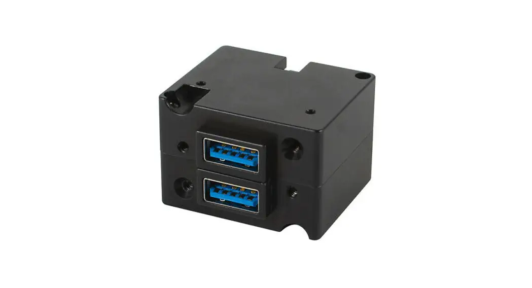
The TA202 Series High Power USB Charging Port is a certified accessory that converts 10 to 32 volts of DC electrical input from the aircraft to standard 5-volt power for any electronic product that charges using a USB connector. The TA202 provides one or two Universal Serial Bus-A or C (USB-A or USB-C) ports and can be rear-mounted or front-mounted in a variety of locations throughout the aircraft. The new “Type-C” USB port design is a smaller port that accommodates the latest consumer electronic devices on the market. Among other features, the Type-C connector accepts reversible cable plugging with no ‘up’ or ‘down’ requirement for cable orientation. The unit is certified to FAA TSO C71 and qualified to multiple RTCA DO-160 requirements, providing confidence and allowing installation in the cockpit or cabin.
This High Power USB Charging Port is designed as a DCP (Dedicated Charging Port) to industry-standard protocol per the USB Battery Charging 1.2 Compliance Plan. It also complies with the higher power requirements of USB Power Delivery 2.0. Newer electronics, such as the Apple iPad ®, other tablets, and larger devices can accept or may require 2.1 amps or more to charge and operate. As a high-power DCP, the TA202 can provide up to 3.0 amps of power to charge USB devices, including higher-demand products. Most dual USB chargers typically provide 1.0 amp on one port and 2.1 amps on the second port, but the TA202 can provide 3.0 amps to both ports simultaneously (for dual-port units). The unit has built-in protections for short circuits, over-current, and low voltage conditions. It is designed to protect against reverse polarity installation and has temperature monitoring and shutdown capability, allowing the unit to handle unforeseen conditions safely.
Small, compact, and powerful, with plenty of installation flexibility, the TA202 is an ideal choice as a highly useful and effective addition to any aircraft.
TECHNICAL SPECIFICATIONS
| Electrical Attributes | |
| Input Voltage | 10-32 VDC |
| Input Power | 35 watts max; 2.5 amps @ 14 VDC / 1.25 amps @ 28 VDC |
| Output Voltage | 5 VDC ±0.25 per port |
| Output Power | 3.0 amps max per port |
| Efficiency | -90% nominal |
Table 1.1
| Physical Attributes | |
| Weight | 1.3 oz. (38 q) (dual port), 0.8 oz. (23 q) (single port) |
| Dimensions (Dual Port Units) (not including connector) | 1.50 inches wide X 1.03 inches high X 1.25 inches deep |
| Dimensions (Single Port Units) (not including connector) | 1.50 inches wide X 0.52 inches high X 1.25 inches deep |
| Charging Ports Type | USB Standard-A or USB Standard-C |
| Connector Kit | MCIA P/N 9017960 |
| Mounting | Panel mount; rear or front |
Table 1.2
| Qualifications | |
| Certification | FAA TSO-C71 |
| EASA ETSO-C71 | |
| Environmental Qualification | RTCA DO-160G Environmental Category See Section 5.2 |
| Airborne Electronic Hardware | RTCA DO-254, Design Assurance Level E |
Table 1.3
| Configurations | ||||
| Non-Lighted | Lighted | Input Power Inp Location | USB Connector | |
| Part Numbers | 6430202-1 | 6430202-11 | Rear | Dual: Type A+Type C |
| 6430202-2 | 6430202-12 | Bottom | ||
| 6430202-3 | 6430202-13 | Rear | Dual: Type C+Type C | |
| 6430202-4 | 6430202-14 | Bottom | ||
| 6430202-5 | 6430202-15 | Rear | Dual: Type A+Type A | |
| 6430202-6 | 6430202-16 | Bottom | ||
| 6430202-7 | 6430202-17 | Rear | Single: Type C | |
| 6430202-8 | 6430202-18 | Bottom | ||
| 6430202-9 | 6430202-19 | Rear | Single: Type A | |
| 6430202-10 | 6430202-20 | Bottom | ||
Table 1.4
SECTION 2 PRE-INSTALLATION CONSIDERATIONS
COOLING
No external cooling is required. The unit will become warm when in use. This is normal and within operational parameters. No special mounting considerations are required; however, mounting to a metal surface can help dissipate any heat generated and extend the life of the product.
EQUIPMENT LOCATION
The TA202 High Power USB Charging Port is designed for mounting flexibility, allowing for installation in the cockpit or in the cabin. It is designed for panel mounting and can be installed in a rectangular configuration or, with an available installation kit, can be front-mounted with a cosmetic cover plate. An instrument mounting adapter bracket is also available to easily mount the unit in a standard 2-inch round instrument opening that may already exist in the cockpit panel. There are two versions to choose from which allow the input connector to be located either on the rear of the unit or from the bottom.
The unit can be mounted in any orientation. Clearance should be provided for the mating connector which may require an additional inch beyond the rear of the unit.
ROUTING OF CABLES
Avoid sharp bends in cabling and routing near aircraft control cables. Avoid close proximity and contact with aircraft structures, avionics equipment or other obstructions that could chafe wires during flight and cause undesirable effects.
LIMITATIONS
Environmental qualifications were verified per RTCA DO-160, Revision G in lieu of those identified within the minimum performance standards (MPS) of the TSO.
The conditions and tests for TSO approval of this article are minimum performance standards.
Those installing this article, on or in a specific type or class of aircraft, must determine that the aircraft installation conditions are within the TSO standards, specification of the article, and deviations as listed above. TSO articles must have separate approval for installation in an aircraft.
The article may be installed only according to 14 CFR part 43 or the applicable airworthiness requirements.
The USB Type-C interface is an exciting new connector for electronic devices. Beyond the physical format of the Type-C connector, it also allows for a variety of interface options when communicating with compatible devices. This device-to-charger communication is defined within the USB 3.1 Specification and Power Delivery 2.0 standards. However, manufacturers of consumer electronic devices and/or cables may choose to implement proprietary versions or modifications of the USB standards to operate specifically with their own charging equipment. The TA202 has been tested with and supports a wide variety of devices now emerging on the open market. However, compatibility with all devices may not be guaranteed. True Blue Power continues to be proactive in evaluating new devices and strives to continually improve the product as needed to serve the vast majority of USB Type-C electronic products.
MODIFICATIONS
This product has a nameplate that identifies the manufacturer, part number, description, certification(s), and technical specifications of the unit. It also includes the “MOD” or modification number representing notable changes in the hardware design of the unit.
Modification (MOD) 0 is the initial release of the product and is identified on the nameplate by the lack of marking on the MOD numbers 1 through 9 (i.e. 1-9 are visible). All subsequent modifications are identified on the nameplate by the marking/blacking out of that particular MOD number (i.e. for MOD 1, the number 1 is not visible and 2-9 are visible – see Figure 2.1 for examples). MODs do not have to be sequentially inclusive and may be applied independently of each other.
For additional details regarding specific changes associated with each MOD status refer to the product published Service Bulletins at www.truebluepowerusa.com.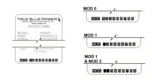
Figure 2.1
Nameplate and MOD Status Example
SECTION 3 INSTALLATION
GENERAL INFORMATION
This section contains interconnect diagrams, mounting dimensions, and other information pertaining to the installation of the TA202 Single and Dual USB Charger. After installation of cabling and before installation of the equipment, ensure that power and ground are applied to the proper pins specified in Section 3.3.2, Pin Assignment information.
UNPACKING AND INSPECTING EQUIPMENT
When unpacking this equipment, make a visual inspection for evidence of any damage that may have occurred during shipment. The following parts should be included:
A. High Power USB Charging Port
B. Installation Manual
C. Connector Kit
| i. Mating Connector, 2-pin ii. Pins (4) (2 required, 2 spares) iii. Screws, #4-40 x 1/4 flat-head (2) iv. Screws, #4-40 x 5/16 flat-head (2) | MCIA P/N 6430202-( ) MCIA P/N 9017899 MCIA P/N 9017960 |
Optional Equipment Available:
| A. Dual Port Front Mount Faceplate Kit B. Dual Port Instrument Mount Adapter Kit C. Dual Port Rear Mount Faceplate Kit D. Single Port Rear Mount Faceplate Kit E. Dual Port Rear Mount Circular Faceplate F. Single Port Rear Mount Circular Faceplate | MCIA P/N 9017897 MCIA P/N 9017947 MCIA P/N 9017958 MCIA P/N 9019351-1 MCIA P/N 9019384-4 MCIA P/N 9019384-3 |
Equipment Not Provided
| A. Cable Harness Wire B. Circuit Breaker Recommendation | See Section 3.3.1 for specifications 3 amp (2 amp may be sufficient for 28V aircraft) |
CABLE HARNESS
Construct the cable harness following the instructions outlined below and per Figure 3.1. Refer to Section 2: Pre-Installation Considerations, for routing precautions.
Wire Gauge Selection
Use of PTFE, ETFE, TFE, Teflon, or Tefzel insulated wire is recommended for aircraft use. The wire harness should utilize 20-24 AWG stranded wire. Refer to table 3.1 below. This table is provided to aid in the consideration of voltage drop due to harness length. Any other wiring standards that are applicable to the installation should also be considered.
| Wire Gauge | Wire Length |
| 20 AWG stranded wire | 24 ft |
| 22 AWG stranded wire | 14 ft |
| 24 AWG stranded wire | 9 ft |
Table 3.1
Wire Gauge and Length
Pin Assignment Information
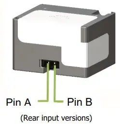
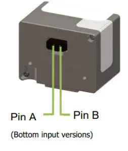
INPUT POWER:
Pin A (keyed) – Positive DC input +10 to 32 VDC power Pin B – Negative DC input/ground
Note: Pins should be crimped using Molex Hand Crimp Tool 63819-0000 (Preferred), 63811-2800 (obsolete) or 11-01-0200 (obsolete). See the Molex Hand Crimp Tool User Manual for crimp procedures.
Harness Verification
 Note:
Note:
The TA202 has built-in reverse polarity protection for the power connector. If Pins A and B are swapped, the unit will not be damaged, but will also not function.
Once the cable harness is prepared, prior to connecting the TA202, activate the aircraft power bus and use a multimeter to verify that aircraft power and ground are supplied with appropriate voltage on the proper pins within the mating harness.
MOUNTING
The TA202 can be installed in one of five ways:
- rear mount, rectangular
- instrument mount
- front mount, decorative faceplate
- rear mount, decorative faceplate
- rear mount, circular faceplate
Installation kit required. See Section 3.2, Optional Equipment Available for part number reference
Dual-port units only
Black anodized
Brushed aluminum, bare (appropriate for additional plating/finish)
Prepare the panel cutout as shown in Figures 3.4 thru 3.11 per the selected mounting option. - Countersinks shown in the panel cutouts for flat head screws are optional. However, flat head screws are provided for a flush appearance. For Rear Mount Cover Plate Installations, countersinks in the panel are required.
- For Rear Mount Installations:
The mounting screw’s length MUST be between (PT +0.150”) and (PT +0.210”). [PT = panel thickness] Mounting screws provided with the unit are 0.24” and 0.31”. (Accommodates 0.030” to 0.160” PT) For PT greater than 0.125, the USB connector will be below the surface of the panel (below flush). - For Front Mount Installations: Minimum panel thickness is 0.04”. Maximum panel thickness is 0.20”.
- For Rear Mount Installation with Cover Plate: Panel thickness greater than 0.065 will cause the USB connector to be below the surface of the Cover Plate (below flush).
INSTALLATION COMPLETION
Prior to operating the unit in the aircraft, it is recommended to verify the output and functionality of the unit. In order to prevent accidental damage to other systems, it is not recommended to attach the output to other equipment prior to verification. Verify the output of the unit at the terminating end of the cable with a multimeter to ensure proper voltage and polarity. Once verified, installation can be completed and functionality should be checked.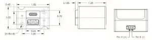
Figure 3.2
TA202 Outline Drawing
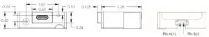
Figure 3.3
TA202 Outline Drawing
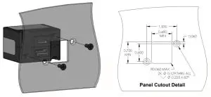
Figure 3.4
Dual Port Rear Mount Installation Kit
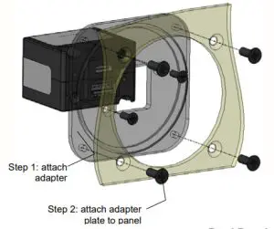
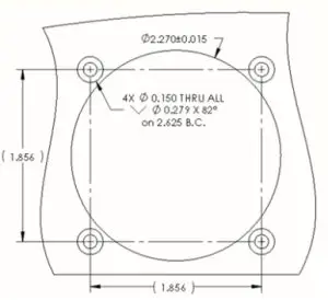
Figure 3.5
Dual Port Instrument Mount Adapter Kit
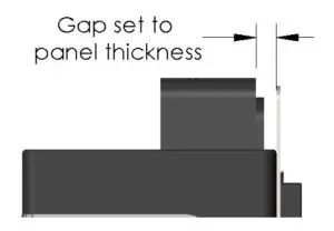
Gap Set Detail
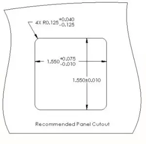
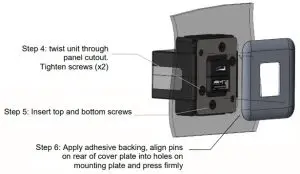
Figure 3.6
Dual Port Front Mount Installation
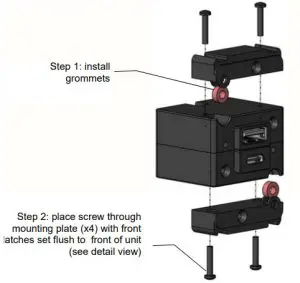
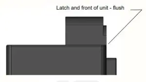
Flush Detail
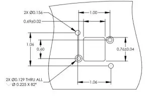
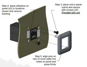
Figure 3.7
Dual Port Rear Mount Faceplate Kit
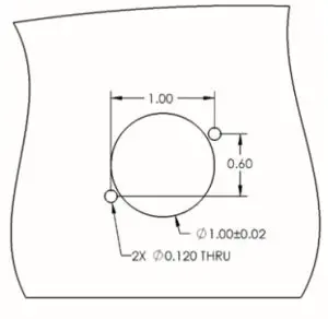
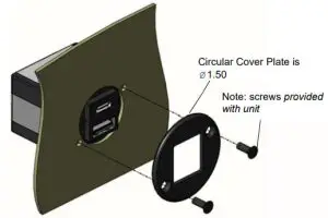
Figure 3.8
Dual Port Rear Mount Circular Faceplate 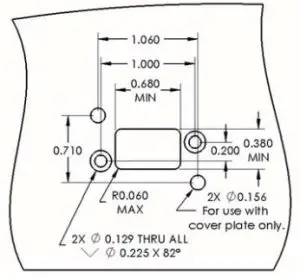
Port protrusion toward the top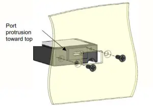
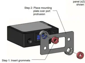
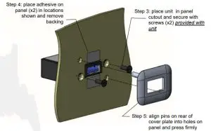
Figure 3.10
Single Port Rear Mount Faceplate Kit
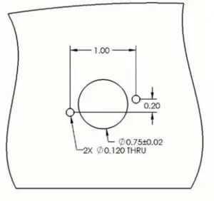
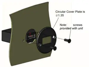
Figure 3.11
Single Port Rear Mount Circular Faceplate
SECTION 4 OPERATION
ELECTRICAL PERFORMANCE
The TA202 Series High Power USB Charging Port converts an aircraft (DC) input voltage within the range specified to a 5V (DC) output. This output power is applied to a single or dual USB-A or USB-C connector in accordance with the USB Implementers Forum.
The USB D+ and D- data lines communicate with the USB portable device to tell the device it is a dedicated charging port (DCP), capable of a higher current than a standard USB port. This allows the USB portable device to draw up to 3.0 Amps.
The unit is designed as a DC-to-DC converter with a series switch on each output to regulate the current applied to that output. Each series switch independently reduces the output current to a safe level if the USB portable device draws excess current, is shorted, or has a fault.
If the temperature of the TA202 becomes elevated due to a fault or excessive load, the device will seamlessly communicate with the USB portable device to lower the charge current. This allows the device to continue charging while the unit returns to a temperature within designed limits. When the temperature returns to a safe level the TA202 will automatically reestablish the higher charge current level with the device and continue charging.
PROTECTIVE FEATURES
Short Circuit Protection
The TA202 is capable of surviving a short circuit event without permanent damage. The unit goes into an over-current condition so that the average current is significantly reduced and the device is protected.
Over-Current Protection
The TA202 monitors the current draw individually on each port. During an overcurrent condition, the voltage is reduced. If the voltage falls below 3.8 VDC the output is turned off for a period of 12 seconds. The output is then checked for continued over-current conditions every 16 milliseconds. This condition is referred to as a hiccup mode. The device stays in this mode until the over-current condition is removed, then returns to normal operation.
Low Input voltage Shutdown
If the input voltage applied to the TA202 drops below 10 VDC the unit will shut down until the applied voltage returns to a level within range.
Over-Temperature
When the internal temperature of the TA202 exceeds designed thresholds, the unit will shut down and stop providing power. When the temperature returns to an acceptable level the unit will automatically begin providing power as required, up to a full charge of 3.0 amps.
SECTION 5 CONFORMANCE
INSTRUCTIONS FOR CONTINUED AIRWORTHINESS
No periodic scheduled maintenance or calibration is necessary for the continued airworthiness of the TA202 series Single and Dual USB Charger. If the unit fails to perform to specifications, the unit must be removed and serviced by Mid-Continent Instruments and Avionics or their authorized designee.
ENVIRONMENTAL QUALIFICATION STATEMENT
MODEL NUMBER: TA202 Series
PART NUMBER: 6430202-( )
DESCRIPTION: Single and Dual USB Charger CERTIFICATION: FAA TSO-C71
MANUFACTURER: True Blue Power, a division of Mid-Continent Instrument Co., Inc.
ADDRESS: 9400 E. 34 th St. North, Wichita, KS 67226, USA.
SPECIFICATION: Test Specification (TS) 365 Test Data Sheet (TDS) 365
STANDARD: RTCA DO- 160, Rev G, dated 12/08/10; MIL-STD-810E, dated 7/14/1989
| CONDITIONS | SECTION | DESCRIPTION OF TEST |
| Temperature and Altitude | 4 | Category Fl |
| Temperature Variation | 5 | Category S2 |
| Humidity | 6 | Category B |
| Operational Shock and Crash Safety | 7 | Category B |
| Vibration | 8 | DO-160: Category R; Curves C, C1 MIL-STD810E: See Remarks |
| Explosion | 9 | Category E |
| Waterproofness | 10 | Category W |
| Fluids | 11 | Category X |
| Sand and Dust | 12 | Category S |
| Fungus | 13 | Category F |
| Salt Spray | 14 | Category S |
| Magnetic Effect | 15 | Category Z |
| Power Input | 16 | Category B(XX) |
| Voltage Spike | 17 | Category B |
| Audio Frequency Conducted Susceptibility | 18 | Category R |
| Induced Signal Susceptibility | 19 | Category X |
| Radio Frequency Susceptibility | 20 | Category X |
| Emission of Radio Frequency Energy | 21 | Category M |
| Lightning Induced Transient Susceptibility | 22 | Category X |
| Lightning Direct Effects | 23 | Category X |
| Icing | 24 | Category X |
| ESD | 25 | Category A |
| Fire, Flammability | 26 | Category C |
REMARKS:
Section 4: Category F1 with excursions as declared by the manufacturer:
4.6.2: Decompression +8,000 to 50,000 feet
Section 7: Crash Safety Impulse: 11ms, 40g Shock Wave
Section 8: Vibration per MIL-STD-810E: Sine-On-Random, Method 514.4, Cat. 4, Procedure 1
truebluepowerusa.com
Manual Number 9017899
Revision K, November 10, 2020


