KICKER VML3Z18808A Amp and Subwoofer Instruction Manual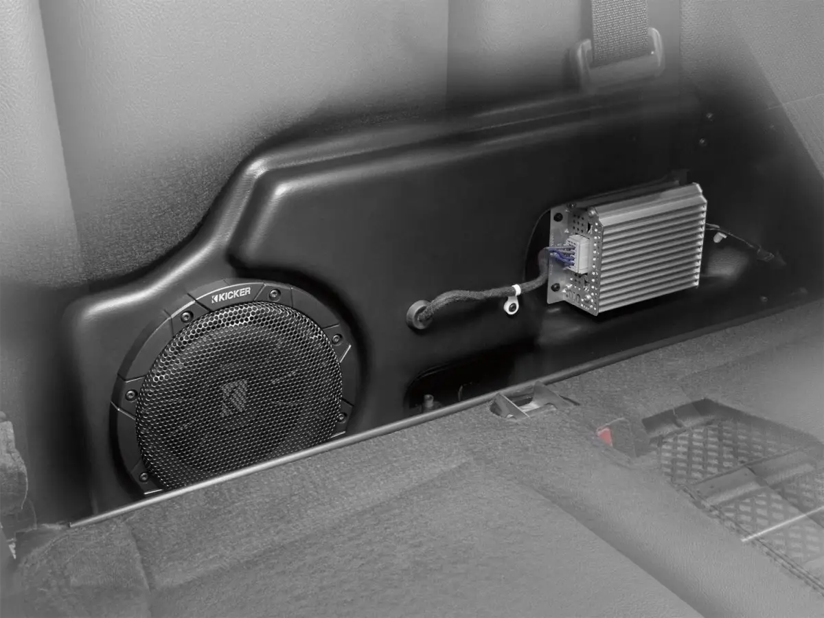
Compatible with radio code ICEHE and speaker code IDBAL or IDBAD in the following vehicles:
2021-present F150 CrewCab
2021-present F150 SuperCab
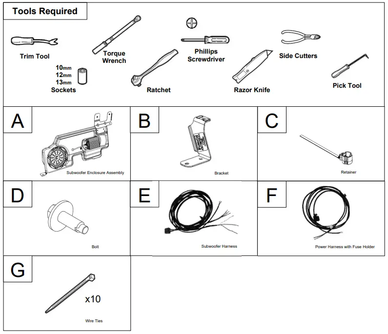
Tools Required
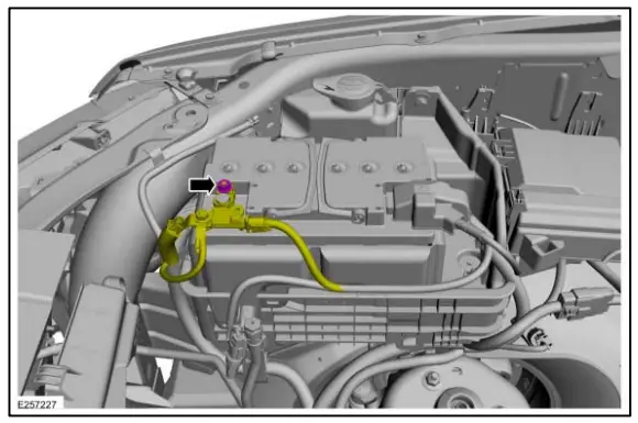
Battery Disconnect
NOTE: When the battery is disconnected and connected, some abnormal drive symptoms may occur while the vehicle relearns its adaptive strategy. The vehicle may need to be driven to allow the PCM to relearn the adaptive strategy values.
- NOTICE: Be careful not to damage the battery monitoring sensor when removing the terminal from the battery post. Do not pry on the terminals or component damage may occur.
NOTE: The following step is to interrupt power to the vehicle’s electrical system. It is not necessary to disconnect the positive battery cable terminal.
Loosen, but do not remove the nut. Position the negative battery cable aside. Torque: 55 lb.in (6.2 Nm)
Power Wire Installation
NOTE: Removal steps in this procedure may contain installation details.
- Release the retainers and remove the battery
junction box cover.
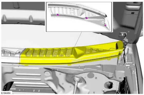
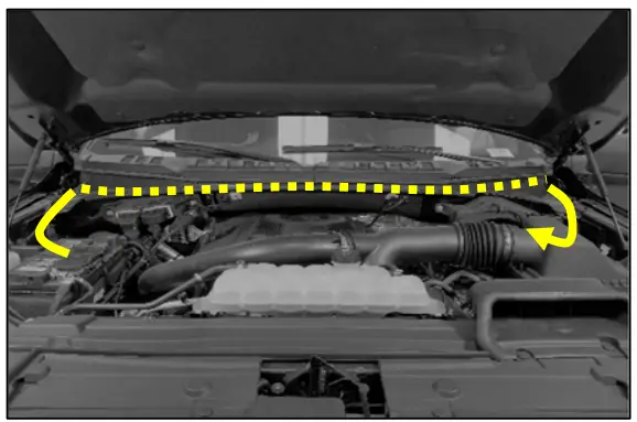
- Lift the cowl trim panel to release the underside pin-type retainers.
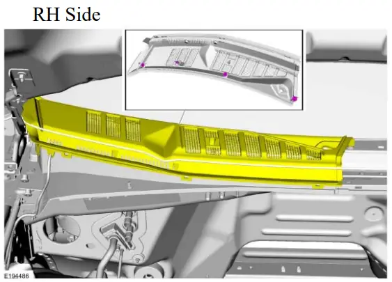
LH Side

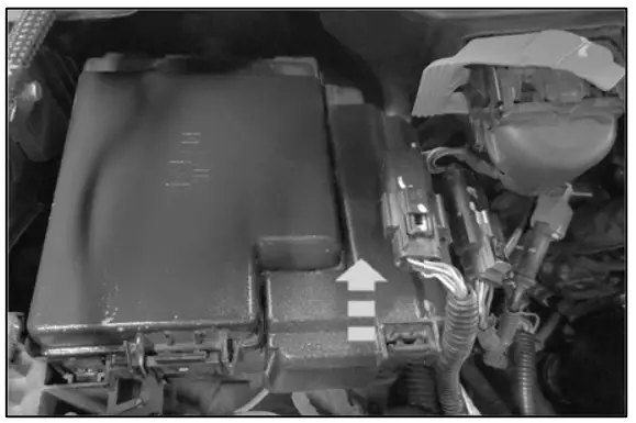
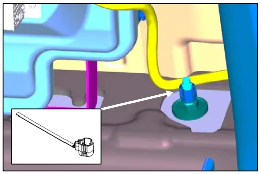
- Remove the Power Distribution Box terminal fastener indicated.
Connect the power harness to the terminal indicated.
Torque: 93 lb.in (10.5 Nm)
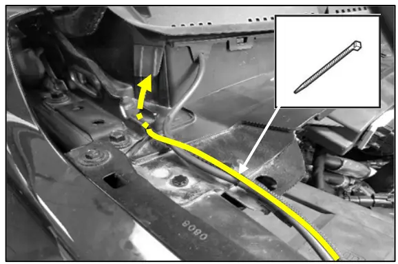
- Route power wire up to cowl opening. Secure with wire ties.

- Route power wire under cowl trim panel and out opening on opposite side.
- Route power wire under bracket and secure to sheet metal with incorporated retainer.
NOTE: Ensure hood hinge mechanism does not interfere with power wire.
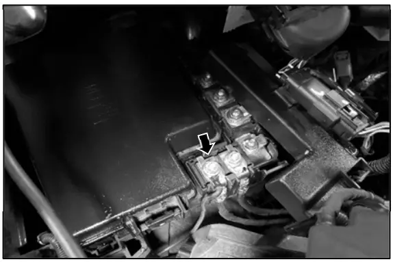
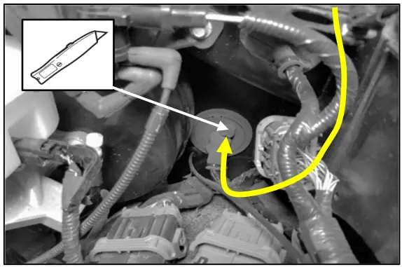
- Make an incision in the rubber grommet and route power wire into cabin.

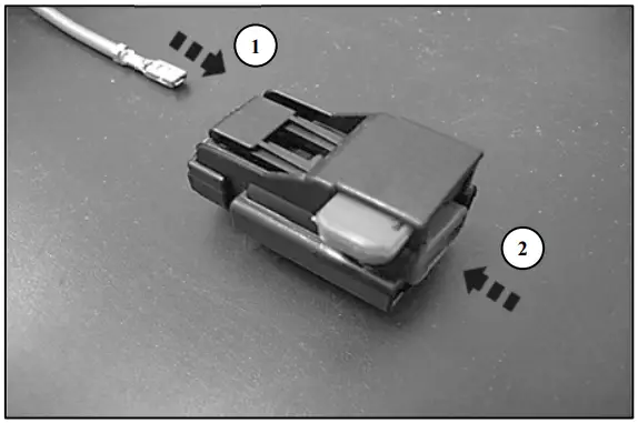
- Install the power wire connector housing on the power wire.
- Insert wires into connector housing.
- Close terminal retainer cap.
Front Controls Interface Module Removal
NOTE: Removal steps in this procedure may contain installation details.
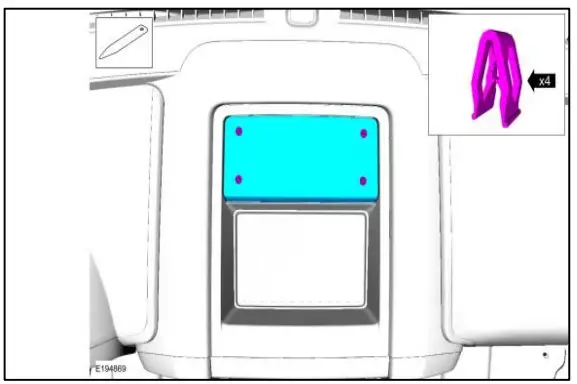
- Release the clips and remove the instrument panel speaker grill.
NOTE: Seven speaker models only Use the General Equipment: Interior Trim Remover. - Remove the bolts, release the clips and remove upper instrument panel storage tray.
Torque: 22 lb.in (2.5 Nm)
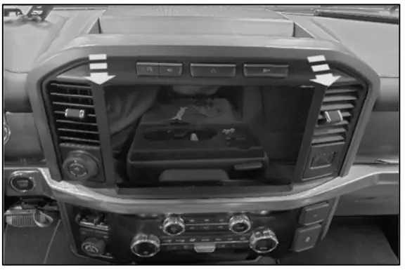
NOTE: Model with instrument panel grill shown. Model without instrument panel grill similar. - Pry loose the center dash trim bezel.
Use the General Equipment: Interior Trim Remover
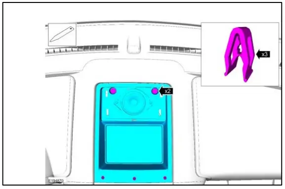
Audio Front Control Module Removal
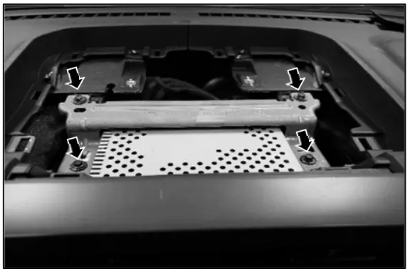
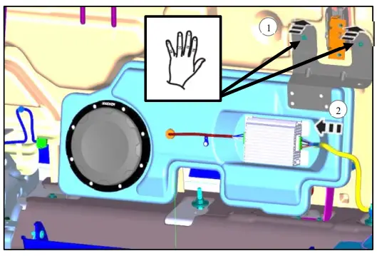
Audio Front Control Module Removal - Remove the four bolts pictured. There are two additional bolts securing the bottom of the module not pictured. Torque: 22 lb.in (2.5 Nm)
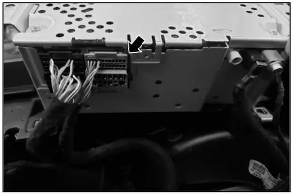
Wire Harness Connection to ACM Connector - Disconnect the connector indicated
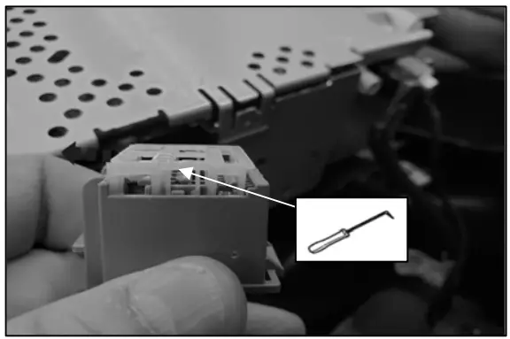
- Using a pick tool, slide the terminal retainer out on both sides until it stops.

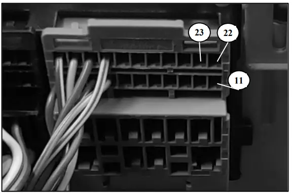
- Find locations 11, 22, and 23 in the connector housing and verify they are not populated. If these locations are populated, discontinue installation and verify system compatibility.
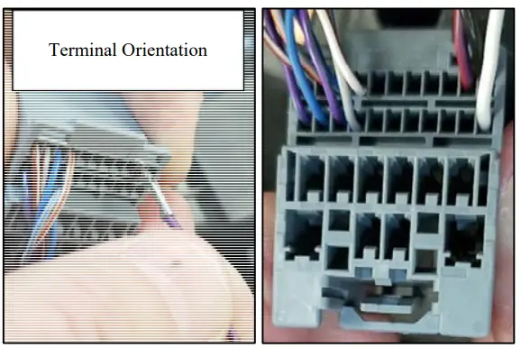
- Insert the terminals into the connector housing.
NOTE: Terminals will not lock into housing if they are not orientated correctly. If the terminal does not lock into housing, flip the terminal 180 degrees and re-insert.
Location 11 – White Wire
Location 22 – Black Wire
Location 23 – Purple Wire
- Press terminal retainer back into the locked position.
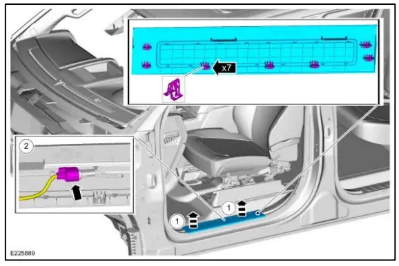
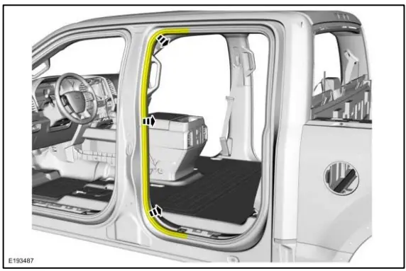
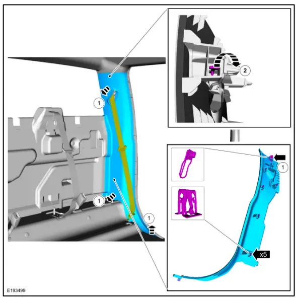
B-Pillar Trim Panel Removal – SuperCrew
NOTE: Removal steps in this procedure may contain installation details.
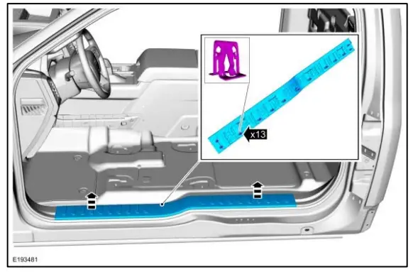
Lower B-Pillar Trim Panel - Remove the front door scuff plate trim panel.
- Release the clips and remove the front door scuff plate trim panel.
- If equipped. Disconnect the electrical connector.
- Release the clips and remove the rear door scuff plate trim panel.

- Position aside the front door weatherstrip.
- Position aside the rear door weatherstrip.
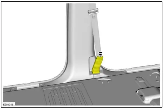
- Release the clips and disengage the safety belt pretensioner boot from the pretensioner bezel.

- Remove the pretensioner bezel.
- Release the clips and remove the lower Bpillar trim panel.


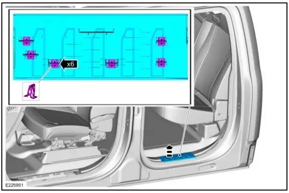
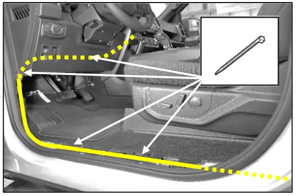
Scuff Plate Removal – Supercab
NOTE: Removal steps in this procedure may contain installation details. - NOTE: The seat is removed for clarity.
Release the clips and remove the scuff plate trim panel.
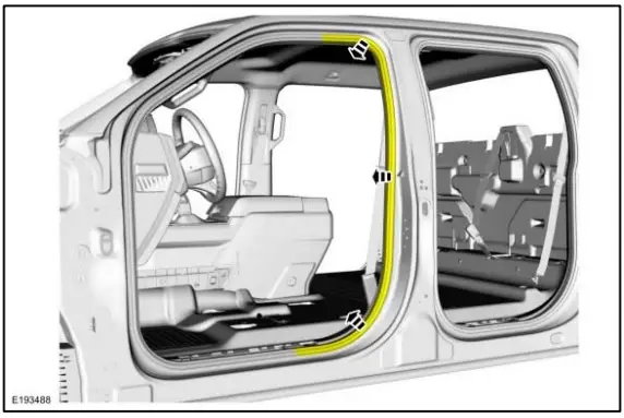
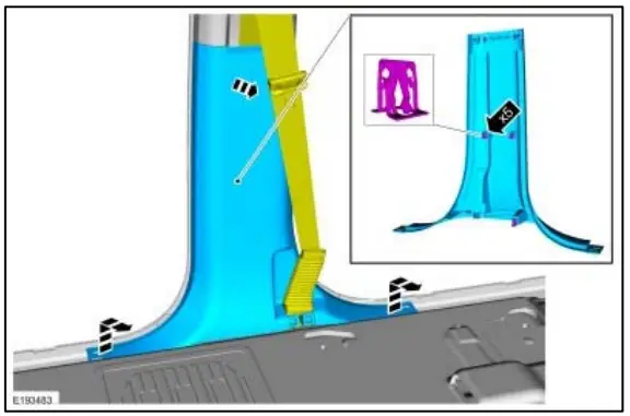
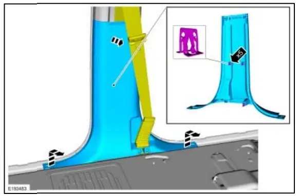
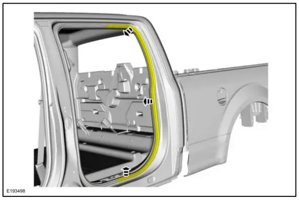
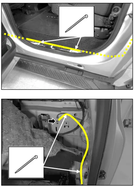
C-Pillar Trim Panel Removal - NOTE: The seat is removed for clarity.
NOTE: Removal steps in this procedure may contain installation details.
NOTE: During installation, make sure to attach the scuff plate trim panels at the lower B-pillar trim panel first. - Position aside the rear door weatherstrip.

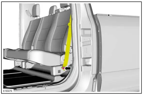
- Remove the bolt and position aside the seatbelt. Torque: 30 lb.ft. (40 Nm)
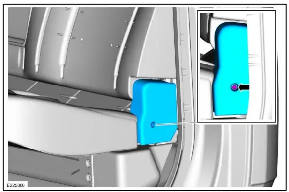
- Remove the retainer and the outboard cushion side shield.

- NOTE: If the tether clip is damaged during removal, a new clip must be installed prior to installation of the panel.
NOTE: During installation make sure to install the clip by the scuff plate trim panel first and work upward on the trim panel to connect the other clips.
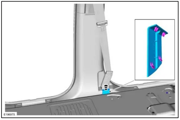
Remove the C-pillar trim panel.- Release the clips.
- Release the tether clip and remove the C-pillar trim panel.

- Route wire harness down the LH side of vehicle from ACM to C-Pillar area.
NOTE: Use supplied wire ties where needed.

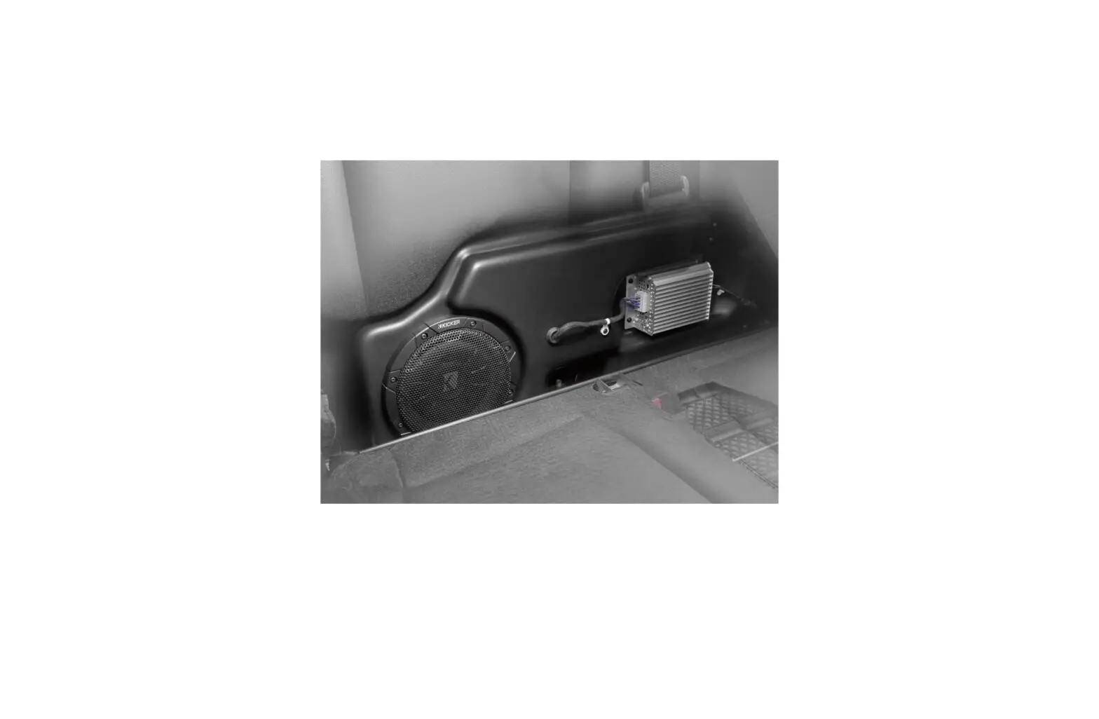
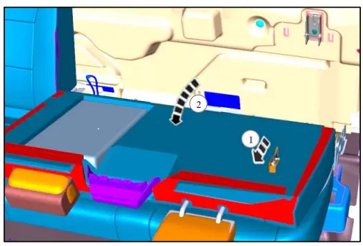
Kicker® Subwoofer Installation
NOTE: Release lever shown with seat in down position for clarity.Fold down the rear seat.
- Pull release lever
- Rotate seat back forward.

- NOTE: Some vehicles may have provisions for subwoofer brackets from the factory and therefore do not require this step.
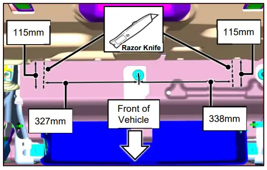
NOTE: It is only necessary to make a cut indicated by the dotted line to allow the vertical portion of the brackets to protrude through carpeting.
NOTE: Cuts must extend to the rear edge of carpet.
Make measurements from the center of the seatbelt stud and from the back wall. Cut the carpet and insulation to allow it to lie over brackets once installed.
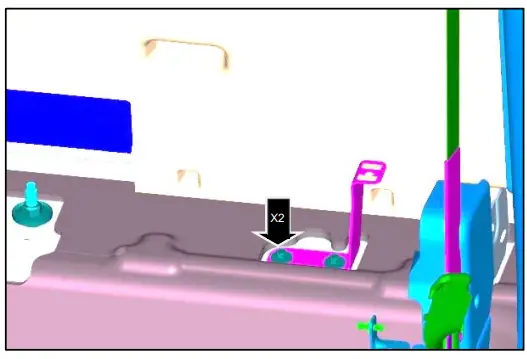
- Install bracket. Torque: 46 lb.in. (5.2Nm)

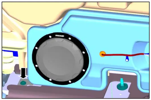
- Lower the subwoofer into position aligning the plastic fastener with bracket hole.

- Install bolt. Torque: 46 lb. in. (5.2 Nm)

- Install supplied retainer around harness at the position marked with blue tape. Trim the excess length of the retainer. Attach the retainer over the stud.

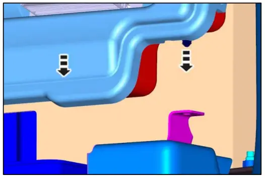
NOTE: Screws and metal retainers are preinstalled in upper bracket and designed to snap into sheet metal as assembled. Do not remove screws or metal retainers during installation. - Cut Carpet to allow upper bracket retainers to snap into metal.
- Press on upper bracket to snap metal retainers into sheet metal.
- Connect harness to amplifier.

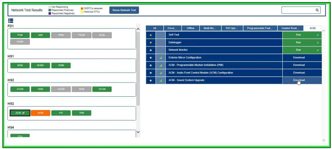
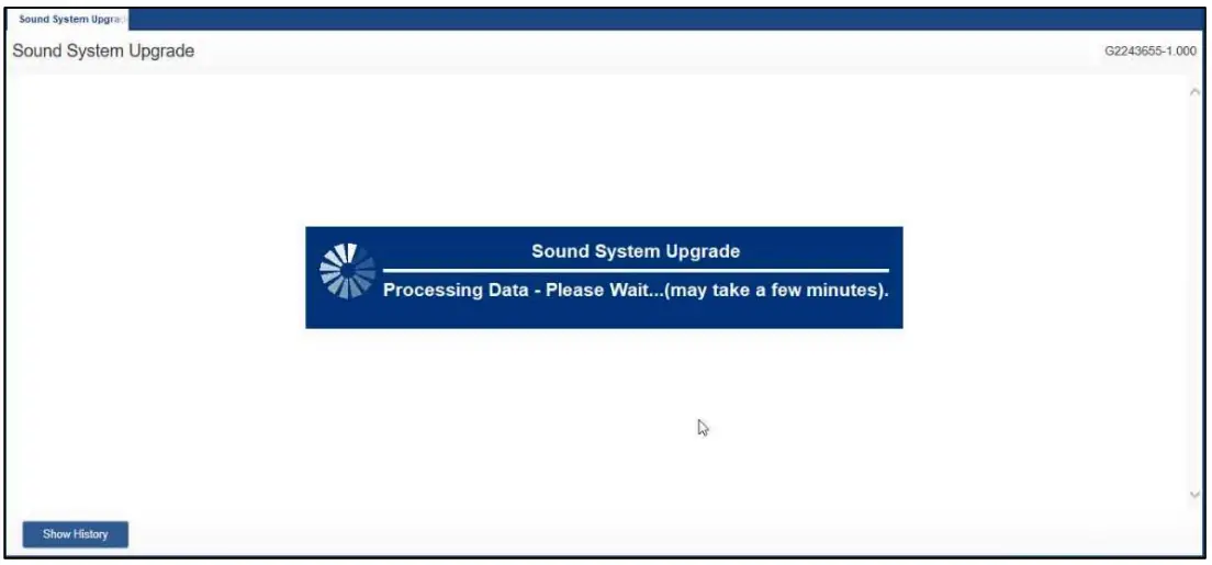
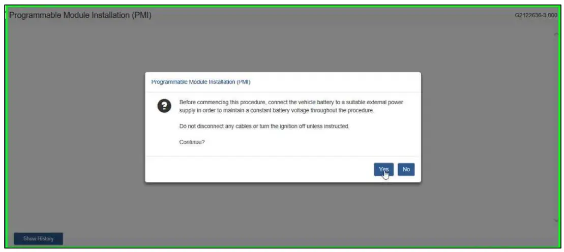
- Open FDRS software and connect to truck.
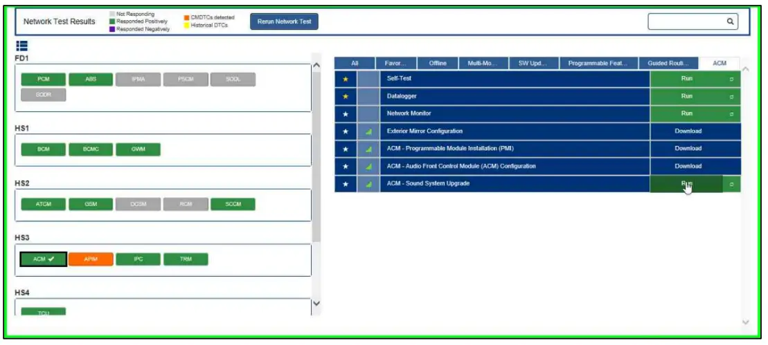
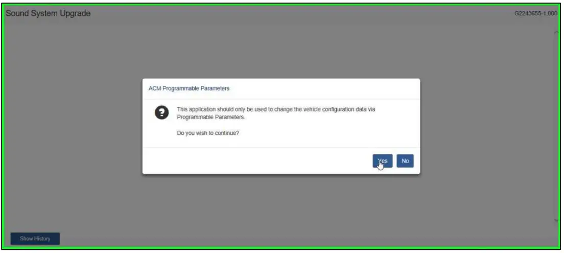
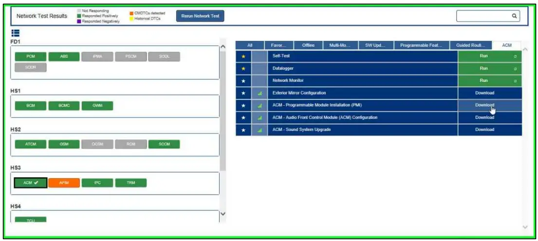
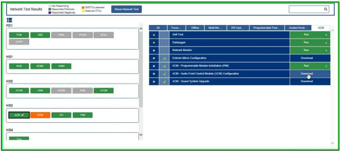
NOTE: Use FDRS software version 28.6.3 or later to complete programming steps. - In the Toolbox tab, select “ACM”. Then select “Download ACM – Sound System Upgrade”. Then select “Run”.


- Select “Yes”.

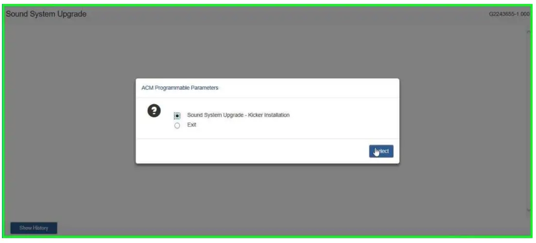
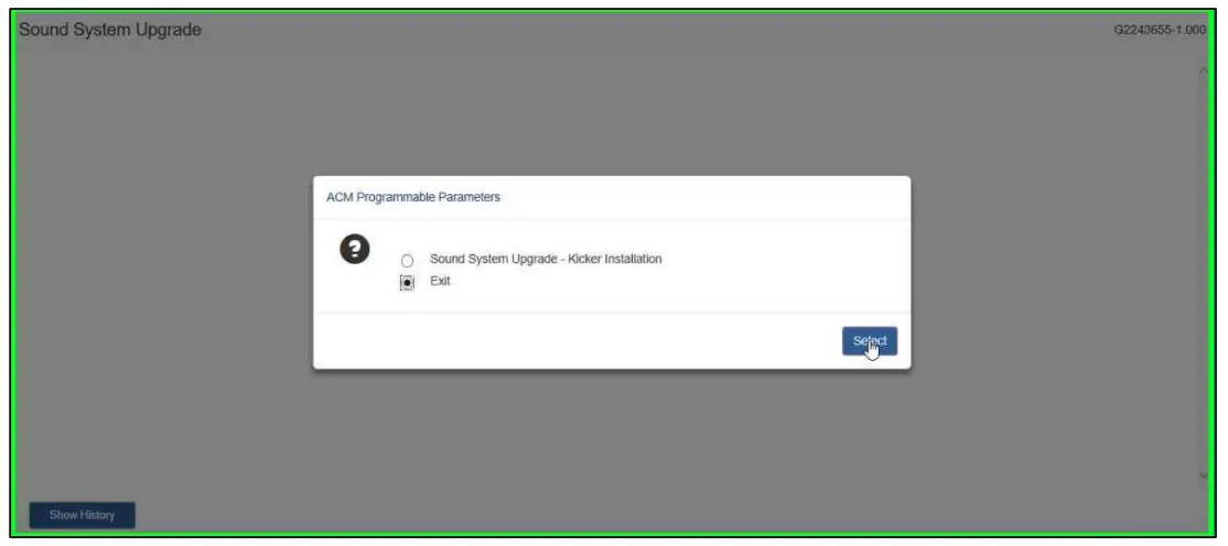
- Select “Sound System Upgrade”.

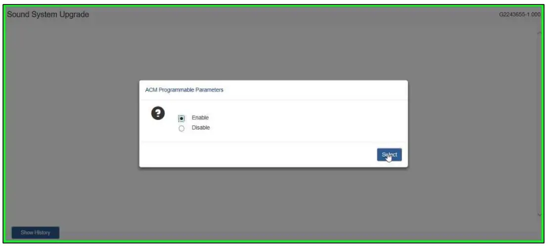
- Select “Enable”.

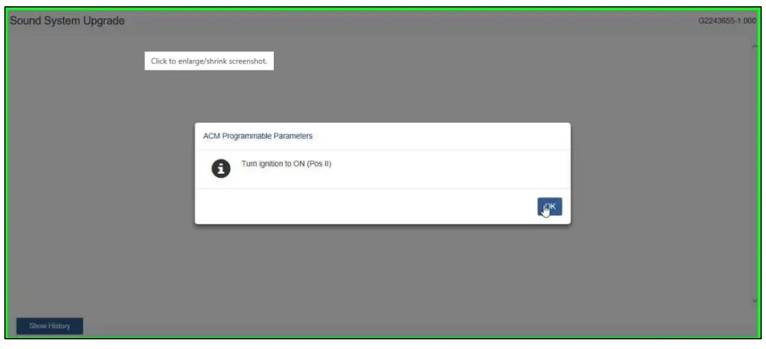
- Turn ignition to “ON (Pos II)” and select “OK”.


- Turn ignition to “OFF (Pos 0)”.

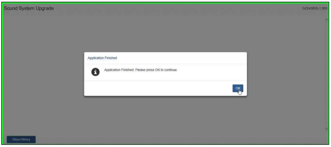
- Select “OK”.

- Select “Exit”.

- Select “OK”.


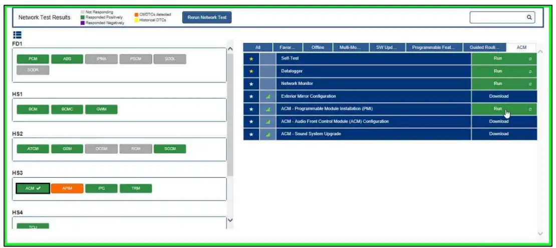
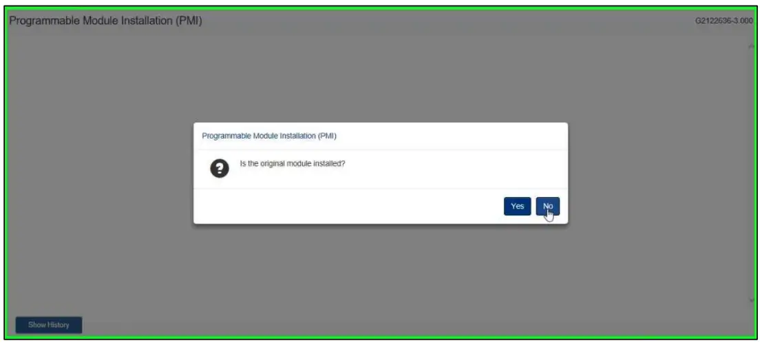
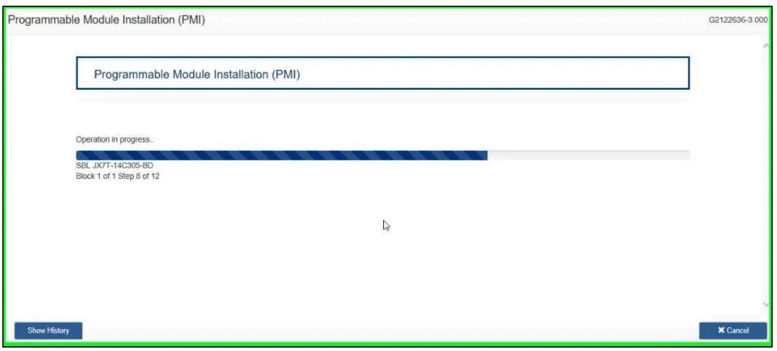
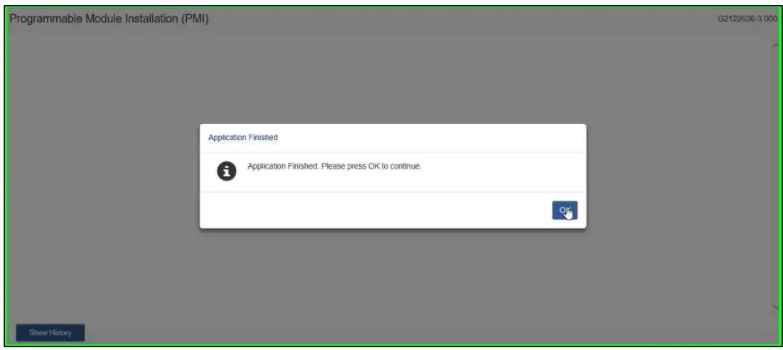
- Select “ACM – Programmable Module Installation (PMI)”. Then select “Download”. Then Select “Run”.


- Select “Yes”.

- Select “No”.

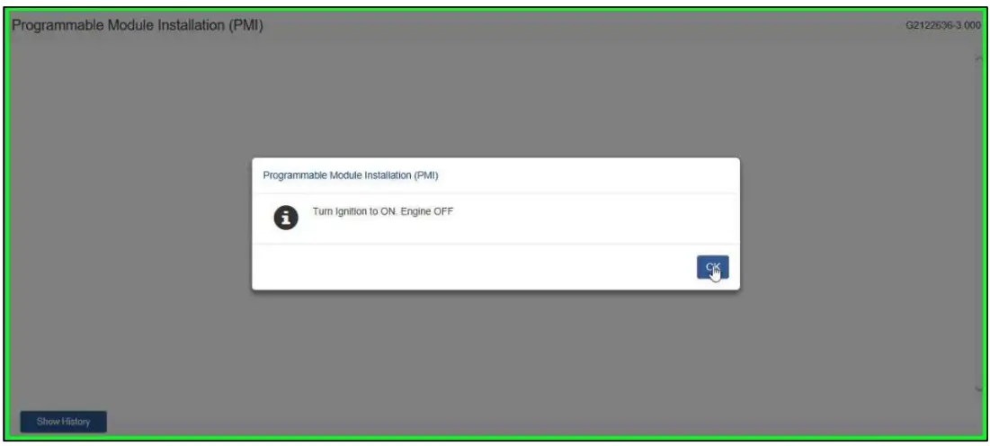
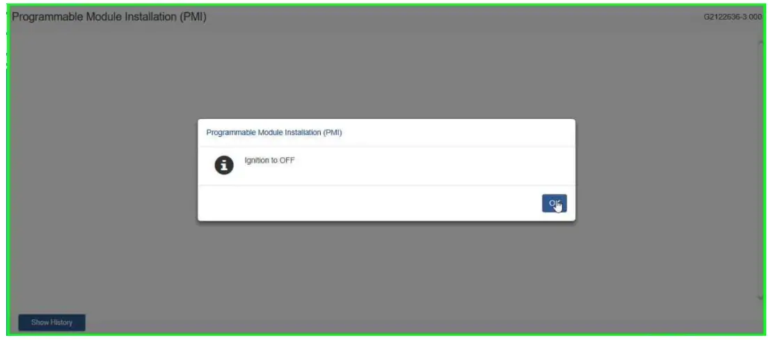
- Turn Ignition to ON. Engine OFF. Select “OK”


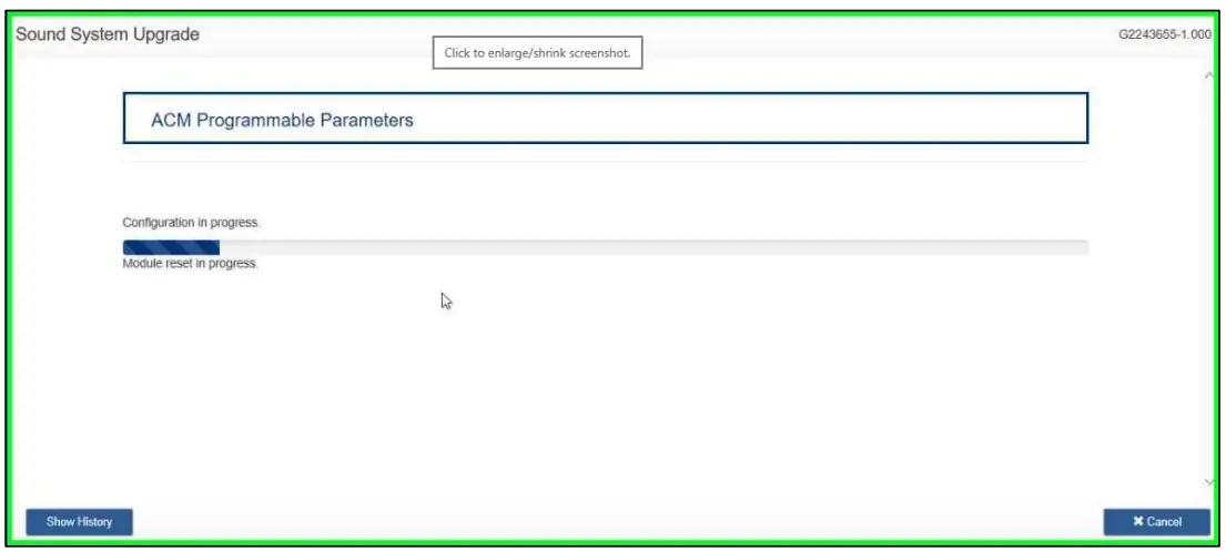
- Turn Ignition to OFF and select “OK”


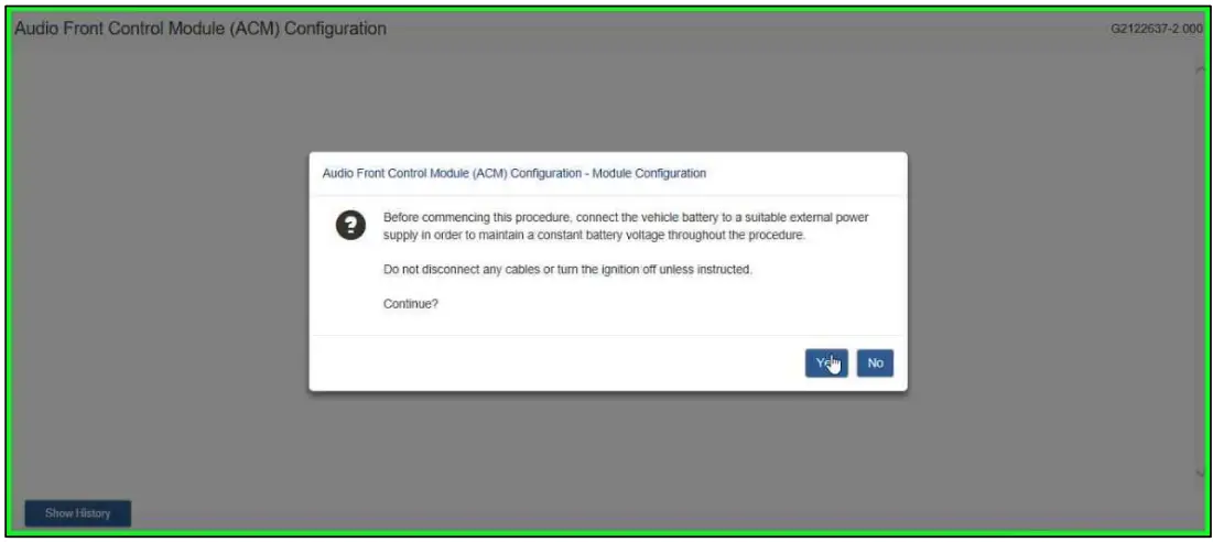
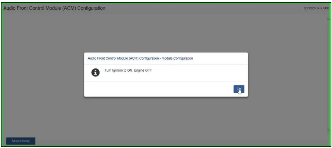
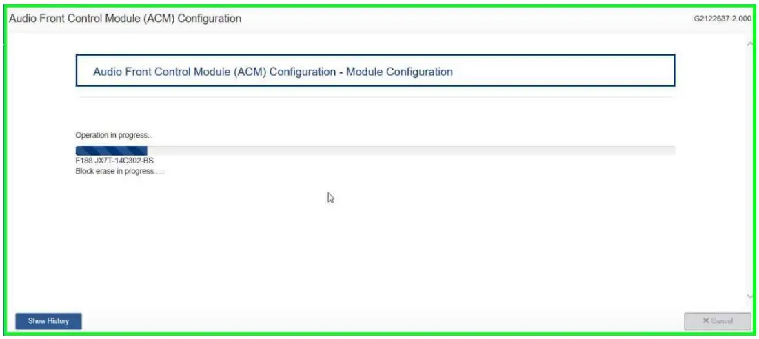
- Select “ACM – Audio Front Control Module (ACM) Configuration”. Then select “Download”.
Then Select “Run” - Select “Yes”.
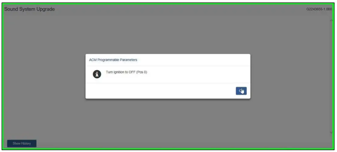
- Turn Ignition to ON. Engine OFF and select “OK”
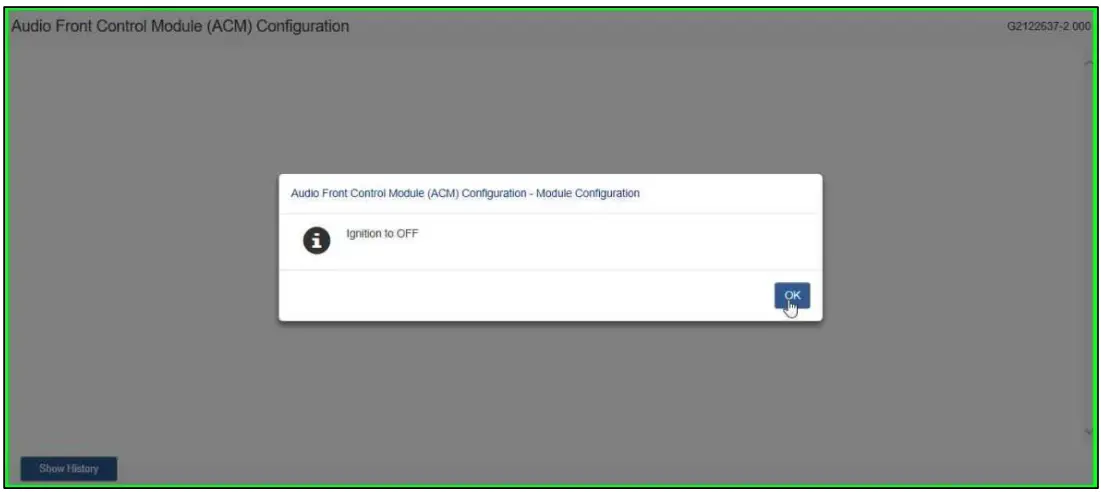
- Turn Ignition to OFF and select “OK”
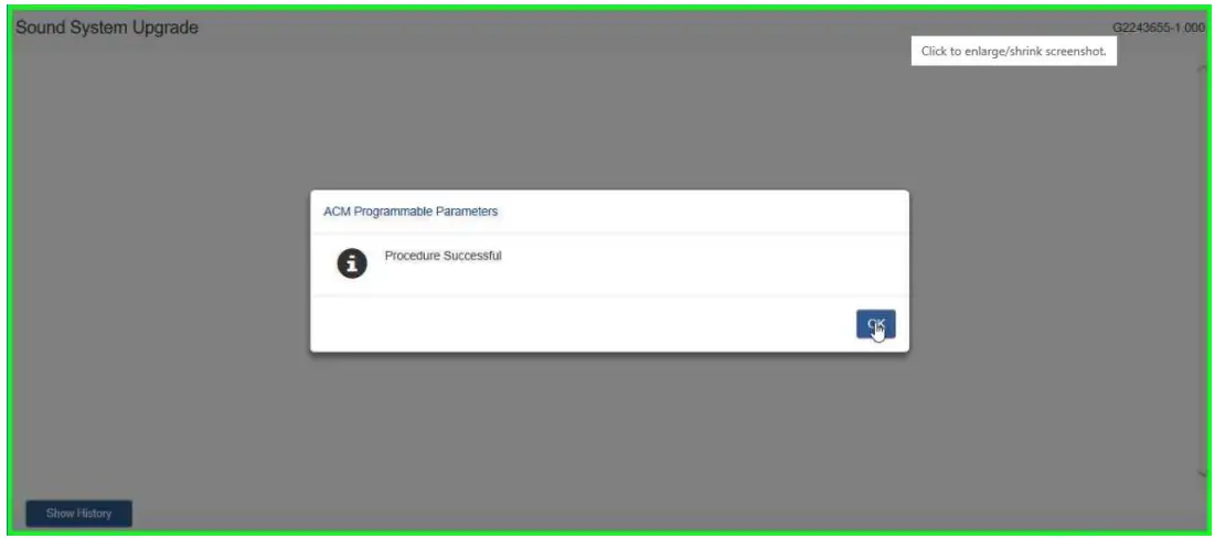
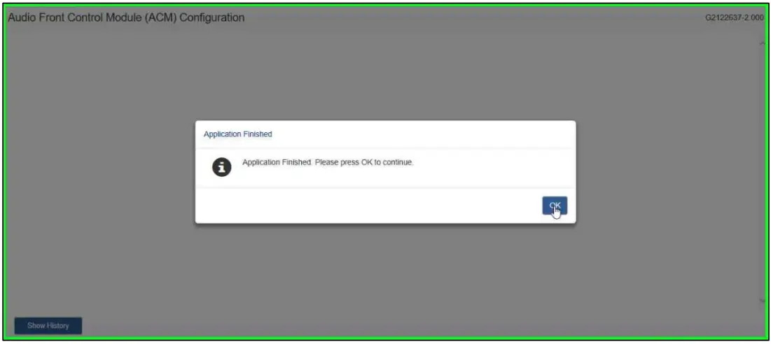
- Select “OK”.


AMML3J19A014AA
VML3Z18808A
Contact KICKER® Technical Support at (800) 256-0808 ext. 6009, or [email protected].
© Copyright Ford 2021 FoMoCo


