ROTENSO Control Series SMART Air Conditioner Detector
PRECAUTIONS
WARNING
Only qualified personnel should install and service the equipment. The installation, starting up, and servicing of heating, ventilating, and air-conditioning equipment can be hazardous and requires specific knowledge and training. Improperly installed, adjusted or altered equipment by an unqualified person could result in death or serious injury. When working on the equipment, observe all precautions in the literature and on the tags, stickers, and labels that are attached to the equipment.
Read the following if you use the device in European countries:
The device can not be operated by children over 7 years old, disabled people and oraz people without experience and knowledge. Instructions should include a description of the correct and safe handling of the device and oraz information about possible dangers. Children should not play with the device. Cleaning and servicing should be carried out by authorized persons.
UTILIZATION:
Do not dispose of this product together with unsorted municipal waste. It’s necessary to transfer this type of waste for special processing. It’s illegal to throw the device together with other household waste. There are several ways to get rid of this type of equipment:w
- The city organizes electronic waste collection, you can pass the device without the cost.
- When you buy a new device the seller will accept the old device without any fees.
- Manufacturers will take the product from the buyer product without charging it with costs.
- Products of this type, contain valuable elements, it can be sold sprzedane on purchase of metals.
Throwing the device,,on wild” exposes you to the risk of losing your health. Dangerous substances from the device can penetrate to groundwater creating a danger of getting through to people’s food chain.
FEATURES
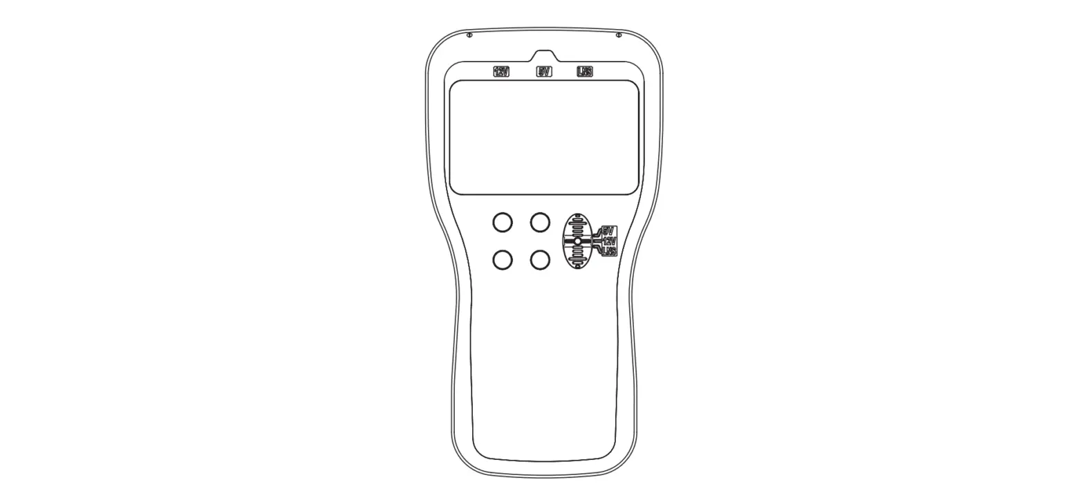
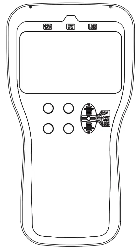
- Portable size with multi-function display
The size is only 180*95*30 mm. The multi-function matrix LCD display can show you complicated information. - Convenient for carrying and operation
The weight is only 400g so that you can carry it easily to the site. Magnet on the back so that you can put it on any metal surface. Menu-style operations make all the detecting, checking and troubleshooting much easier. - Easy connection
You can connect it to inverter air conditioner directly at the terminals without disassembling the indoor or outdoor unit. - Powerful functions
With it you can check the communication, running parameters, error codes and set the running parameters of inverter air conditioners.
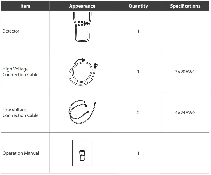
PACKING LIST
Please check if all items are inside the packing box when you get the detector.
PART NAME
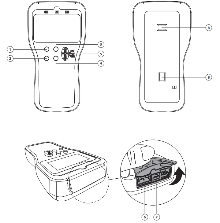
- UP button
- DOWN button
- OK button
- BACK button
- Connection selector
- Port for high voltage connection
- Port for low voltage connection
- Magnet
OPERATIONS
- UP and DOWN button:
For item selection, or page up and down in parameter inquiry mode, or increase and decrease the values in parameter setting mode. Press and hold them more than 5s if you want to adjust the values fast. - OK button
Confirm selection. Press and hold it for 3s, the device will directly go to the “Information Inquiry – Parameter Inquiry” function. - Back button
Back to the upper menu. Press and hold it for 3s, the device will go to the Primary Menu. - Connection Selector and Connection Ports
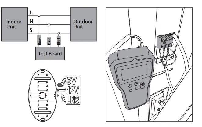
For selecting the right connection and power supply to the detector.- LNS: For a high voltage connection with the 3-core cable with a white connector, the other side is to be connected to the terminal of the inverter outdoor unit.
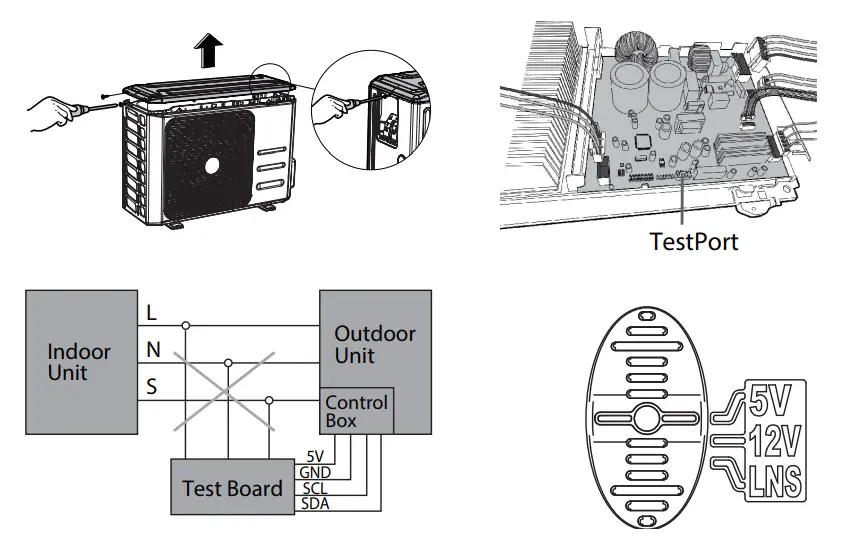
- 5V: For low voltage connection with the 4-core cable with a white connector, the other side is to be connected to the Westport on the main PCB of the inverter outdoor unit.
Abbreviations
| Designation | Description |
| IDU | Indoor unit |
| ODU | Outdoor unit |
| Temp. | Temperature |
| Freq. | Frequency |
| Ctrl. | Control |
| PMV | Electrical expansion valve |
| Err. | Error |
| 4WV | 4 way valve |
| Para. | Parameter |
| Volt. | Voltage |
| Curr. | Current |
| Comp. | Compressor |
| Commu. | Communication |
| T1 | Room temperature |
| T2 | Indoor coil temperature |
| T3 | Outdoor coil temperature |
| T4 | Ambient temperature |
| T5/Td | Compressor discharge temperature |
Menu Structure
| Primary Menu | Secondary Menu | 3rd level Menu | Remark |
|
Information Inquiry | Parameter Inquiry |
For 5V TestPort connection only | |
| AD Value Inquiry | |||
| Error Code Inquiry | |||
|
Parameter Setting | Target Frequency | ||
| Outdoor Fan Speed | |||
| Open Steps of PMV | |||
| 4-way Valve | |||
|
Commu. Error Analysis | Self-check |
For LNS connection only | |
| Online Check | |||
| Check Indoor PCB | |||
| Check Outdoor PCB | |||
|
Commu. Simulation | Information inquiry | IDU Query | |
| ODU Query | |||
|
IDU Simulator | Mode | ||
| Target Frequency | |||
| Fan speed | |||
| Indoor Temp. T1 | |||
| Evaporator Temp. T2 | |||
|
ODU Simulator | Mode | ||
| Running Frequency | |||
| Condenser Temp. T3 | |||
| Ambient Temp. T4 | |||
| Discharge Temp. T5 |
OPERATION INSTRUCTIONS
ATTENTION!
Before commencing any tests, SWITCH-OFF ALL POWER SOURCES and WAIT for a MINIMUM OF 3 MINUTES to allow all capacitor voltages to decay. Before disconnecting of connecting any terminals, check that all voltages are zero. For LNS connection (Suitable for AC units with S communication) Connect this device to the void pins of outdoor wiring terminal with LNS connection cable. Make the Connection selector to “LNS”.
Note:
- For convenience, you can move some wires from front pins to back pins so that you can connect the device on the front pins.
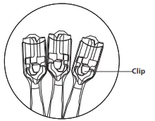
- There is a clip inside the terminal of the connection wire. Always make the front side face you when you insert the terminal into the pins. Or you cannot press the clip when you want to put the terminals out of the pins.

- Watch the sequence of L, N and S when you connect the device to the terminal.
Commun. Error Analysis
- When the device is connected and powered on, it will carry out the communication check automatically.
- You may get any of the below 3 feedbacks in about 40 seconds:
- IDU commu. fault, please check the IDU and communication wire;
- ODU commu. fault, please check ODU and communication wire;
- Communication normal, Please press OK for information. (When OK pressed, it will go to “Commu. Simulation—Information inquiry” directly)
Note: If you get c) result but E1 still shows, the indoor PCB is faulty and need to be replaced.
- If you want to check the communication again, go to “Commu. Error Analysis—Online check”.
- Self-check
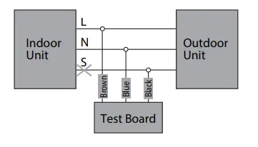
This function is to ensure the communication check function of the device is normal. Disconnect S (only L, N connected) and turn on the A/C unit, select “Commu. Error Analysis self-check”, you will get the feedback in about 10 seconds.
Note: Self-check is unnecessary for each analysis.
Information Inquiry
Select “Commu. Simulation—Information inquiry—IDU inquiry” to check the indoor unit running parameter. Select “Commu. Simulation—Information inquiry—ODU inquiry” to check the outdoor unit running parameter.
| IDU information | Data Range | ODU information | Data Range |
|
Mode | OFF COOL HEAT ONLY FAN DRY FORCE COOL DEFROST |
Mode | OFF COOL HEAT ONLY FAN DRY FORCE COOL DEFROST COOLDRY (Self-clean) ECO |
| Target Frequency | 0~255 | Frequency | 0~255 |
| Room Temp. | -66.0~255 | AC Input | 0~65535 |
| Coil Temp. | -66.0~255 | ||
|
Indoor Fan Speed | OFF High Middle Low Sneeze Turbo Supper Sneeze Auto |
Ambient Temp. |
-66.0~255 |
| Set Temp. | 17-30 | Coil Temp. | -66.0~255 |
| Discharge Temp. | -66.0~255 | ||
| ODU Fan speed | 0~65535 | ||
| PMW steps | 0~65535 |
Indoor Unit Simulator
In this mode, the device can work as an indoor unit. You can set necessary parameters like values of room temperature senor T1, coil temperature sensor T2, target running frequency of compressor, mode, fan speed, even fault information and send them to outdoor unit to change the working state of it.
Note: The communication cable S should be disconnected to the indoor unit.
Outdoor Unit Simulator (Reserved)
For 5V Test Port Connection (Suitable for all inverter AC units) Remove the top cover of the inverter outdoor unit and find the main PCB. Connect this device to the TestPort on the main PCB of the outdoor unit. Make the Connection selector to “5V”.
Note: Never connect LNS and Westport at the same time.
Information Inquiry
Select “Information Inquiry—Parameter Inquiry” to check the running parameters of the inverter unit.
| Information | Data Range |
| Indoor target frequency | 0~255 |
| Outdoor target frequency | 0~255 |
| Outdoor control frequency | 0~255 |
| Outdoor actual frequency | 0~255 |
| Room temp. T1 | -66.0~255 |
| Indoor coil temp. T2 | -66.0~255 |
| Outdoor coil temp. T3 | -66.0~255 |
| Ambient temp. T4 | -66.0~255 |
| Discharge temp. Td | -66.0~255 |
| IPM temp. | -66.0~100 |
| Outdoor Fan Speed | 0~65535 |
| PMV opening steps | 0~65535 |
| Set temp. Ts | -66.0~255 |
| Indoor mode | OFF, COOL, HEAT, ONLY FAN, DRY, FORCE COOL, DEFROST |
| DC bus volt. | 0~65535 |
| AC volt. | 0~65535 |
| Current | 0~65535 |
AD Value Inquiry (Reserved)
Error Code Inquiry
You can check the error code if there is any. When error occurs, the display will show error code and the information you’re checking alternatively every two seconds.
| Error Code | Explanation |
| E0 | Indoor EEPROM error |
| E1 | Communication error of indoor and outdoor unit |
| E2 | Error of zero cross detection of indoor unit |
| E3 | Indoor fan out of control |
| E5 | EERROM or temperature sensor error of outdoor unit |
| E50 | Temperature sensor error of outdoor unit |
| E51 | Outdoor EEPROM error |
| E6 | Temperature sensor error of indoor unit |
| Error Code | Explanation |
| E60 | Error of room temperature sensor of indoor unit |
| E61 | Error of evaporator temperature sensor of indoor unit |
| E7 | DC fan of outdoor unit out of control |
| Eb | Error of communication between indoor PCB and display PCB |
| P0 | IPM Module protection of outdoor unit |
| P1 | Voltage protection |
| P10 | Low voltage low protection |
| P11 | Over voltage protection |
| P12 | Error of 341MCE |
| P2 | Top temperature protection of compressor |
| P4 | Feedback protection of compressor in outdoor unit |
| P40 | Communication error between main control trip and drive chip |
| P41 | Error of current sampling circuit of compressor |
| P42 | Error of compressor start up |
| P43 | Phase lose protection |
| P44 | Zero speed protection |
| P45 | Synchronization error between 341 chip and PWM |
| P46 | Compressor speed out of control |
| P49 | Error of over current of compressor |
| P6 | High discharge temperature protection of compressor |
| P8 | Current protection |
| P80 | Current protection of indoor unit |
| P81 | Current protection of outdoor unit |
| P82 | Error of sampling of input AC |
| P9 | High and low temperature protection of evaporator |
| P90 | High temperature protection of evaporator |
| P91 | Low temperature protection of evaporator |
| PA | High temperature protection of condenser |
| L0 | Frequency limit caused by High or low evaporator temperature |
| L1 | Frequency limit caused by high condenser temperature |
| L2 | Frequency limit caused by high discharge temperature of compressor |
| L3 | Frequency limit caused by current |
| L5 | Frequency limit caused by voltage |
| PF | PFC circuit error |
Parameter Setting
Select “Parameter Setting”, you can set the frequency of compressor, outdoor fan speed, opening steps of electrical expansion valve and 4-way valve.
| Contents | Valid Range | Remark | ||
| Target Frequency | 0.1~200 | Please refer to recommended range | ||
|
Outdoor Fan Speed | 0~1599 | DC Motor | ||
|
0~1599 |
AC Motor | 0~Min. Speed rpm | Auto (by unit) | |
| Min. Speed ~800 rpm | Low | |||
| 800~1200 rpm | Med | |||
| 1200~1500 rpm | Hi | |||
| Open Steps of EEV | 0~1599 | |||
|
4-way Valve |
0~2 | 0 | Auto (by unit) | |
| 1 | On | |||
| 2 | Off | |||
WARNING!
DO NOT let compressor run at very high frequency or some certain frequency leading to resonance for a long time to avoid damage to compressor or the inverter control system.
Recommended set frequency range
| Unit size | Cooling Mode | Heating Mode | ||||
| Min | Suitable | Max | Min | Suitable | Max | |
| 12K and lower | 14 | 25-65 | 85 | 26 | 35-75 | 90 |
| 18-24K | 18 | 25-65 | 75 | 26 | 35-75 | 85 |
| 36-60K | 20 | 30-60 | 70 | 26 | 35-70 | 80 |
ATTENTION!
Any damage of inverter A/C units caused by the set frequency out of above range is the responsibility of the operators themselves.
email: [email protected]


