![]()
POWER COMMANDER 6
Installation Guide for PC6-17022
Model Coverage: 2010-2014 Kawasaki Concours 1400
PC6-17022 Power Commander 6
PARTS LIST
1 POWER COMMANDER 6
1 INSTALLATION GUIDE
1 USB CABLE
2 DYNOJET DECALS
2 POWER COMMANDER DECALS
2 VELCRO STRIPS
1 ALCOHOL SWAB
PLEASE READ ALL DIRECTIONS BEFORE STARTING INSTALLATION.
THE IGNITION MUST BE TURNED OFF BEFORE INSTALLATION.
INPUT ACCESSORY GUIDE
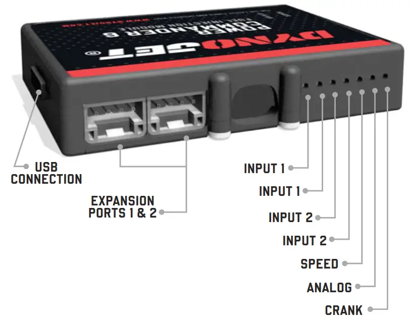
OPTIONAL ACCESSORY INPUTS
Map
(Input 1 or 2) The PC6 has the ability to hold 2 different base maps. You can switch on the fl y between these two base maps when you hook up a switch to the MAP inputs. You can use any open/close type switch. The polarity of the wires is not important.
Shifter
(Input 1 or 2) Used for clutch-less full-throttle upshifts. Insert the wires from the Dynojet quick shifter into either Input 1 or Input 2. The polarity of the wires is not important. Set to Input 2 by default.
Speed
If your application has a speed sensor then you can tap into the signal side of the sensor and run a wire into this input. This will allow you to calculate gear position in the Control Center Software. Once gear position is set up you can alter your map based on gear position and setup gear-dependent kill times when using a quick shifter.
Analog
This input is for a 0-5v signal such as engine temp, boost, etc. Once this input is established you can alter your fuel curve based on this input in the Power Core software.
Launch You can connect a wire to either Input 1 or Input 2 and then the other end to a switch. This switch when engaged (continuity) will only allow the RPM to be raised to a certain limit (set in the software). When released, you will have full RPM.
WIRE CONNECTIONS
To input wires into the PC6 first remove the rubber plug on the backside of the unit and loosen the screw for the corresponding input. Using a 22-24 gauge wire, strip about 10mm from its end. Push the wire into the hole of the PC6 until it stops and then tightens the screw. Make sure to reinstall the rubber plug.
NOTE: If you tin the wires with solder it will make inserting them easier.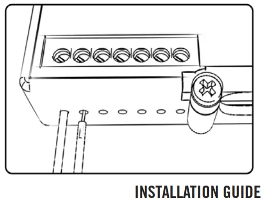
2 2010-2014 KAWASAKI CONCOURS 1400
INSTALLING THE POWER COMMANDER 6
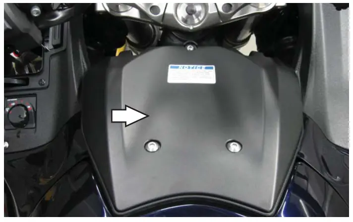
- Remove the left-hand fairing and inner fairing panel.
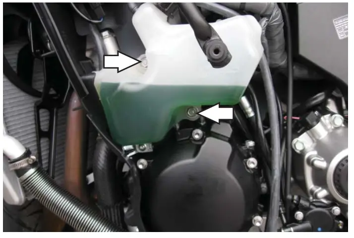
- Remove the cover on the top of the fuel tank.

- Remove the coolant reserve bottle by removing the two mounting bolts.
You do not need to disconnect the hoses. Just move the bottle out of the way for easier access to the wiring harness.
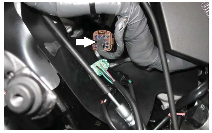
- Unplug the stock wiring harness from the throttle bodies.
This is a 16-pin BROWN connector pair.
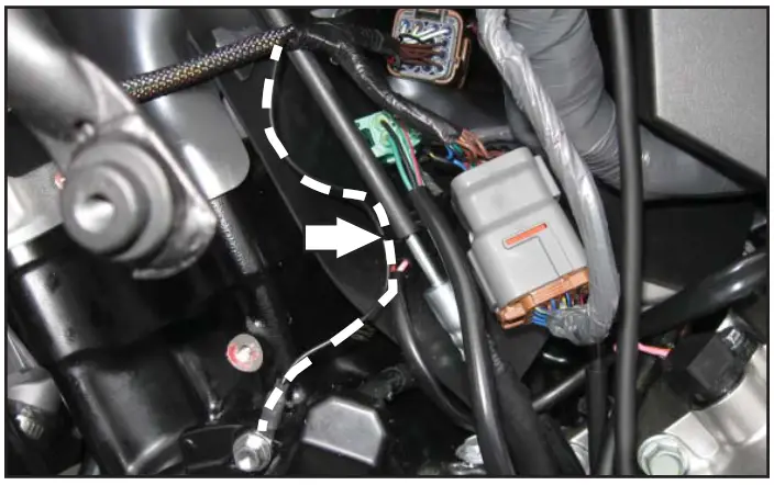
- Plug the PC6 harness in line with the stock wiring harness and throttle bodies.
- Attach the ground wire from the PC6 to the engine case bolt.
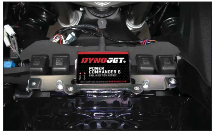
- Reinstall the coolant bottle.

- Using the supplied Velcro secure the PC6 to the relay bracket.
Clean both surfaces with the supplied alcohol swab prior to applying the Velcro adhesive. - Reinstall the bodywork.
Note: If using the software to reset the throttle position make sure the bike is up to full operating temperature before doing so.
Download the latest map files from our website at dynojet.com/tunes.
Optional Inputs:
Speed Input – PINK wire on speed sensor. Located on the left side of the engine near the output shaft.
12v Source for Autotune – RED/BLUE wire of tail light.
Use wire going to the fuse box.
4 2010-2014 KAWASAKI CONCOURS 1400
INSTALLATION GUIDE
PUSH THE LIMIT
2191 MENDENHALL DRIVE, NORTH LAS VEGAS,
NV 89081 – 800-992-4993 – DYNOJET.COM
© 2010-2022 DYNOJET RESEARCH ALL RIGHTS RESERVED![]()


