Godox WMicS1 Pro TX UHF Full Metal Dual-Channel Wireless Microphone System Instruction Manual
Thank you for purchasing!
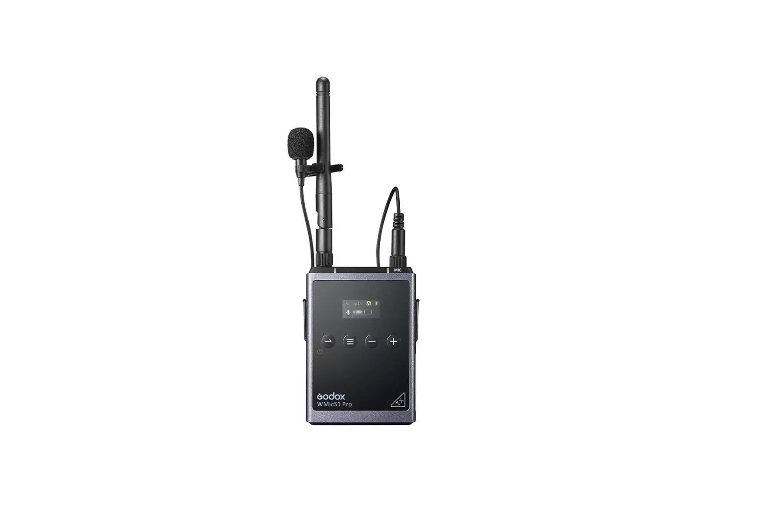
WMicS1 Pro is the metal UHF wireless microphone system, which is suitable for video recording, journalistic shooting, audio recording, etc.
Please read this manual carefully before using to make sure the correct operation and exert the optimum function. And well keep it for future reference.
Safety Instructions
Warning
![]() Do not disassemble. Should repairs become necessary, this product must be sent to an authorized maintenance center.
Do not disassemble. Should repairs become necessary, this product must be sent to an authorized maintenance center.
![]() Always keep this product dry. Do not use in rain or in damp conditions.
Always keep this product dry. Do not use in rain or in damp conditions.
![]() Keep out of reach of children.
Keep out of reach of children.
![]() Do not use the flash unit in the presence of flammable gas. In certain circumstance, please pay attention to the relevant warnings.
Do not use the flash unit in the presence of flammable gas. In certain circumstance, please pay attention to the relevant warnings.
![]() Do not leave or store the product if the ambient temperature reads over 40°C.
Do not leave or store the product if the ambient temperature reads over 40°C.
![]() Turn off the flash trigger immediately in the event of malfunction.
Turn off the flash trigger immediately in the event of malfunction.
![]() Observe precautions when handling batteries.
Observe precautions when handling batteries.
- Use only batteries listed in this manual. Do not use old and new batteries or batteries of different types at the same time.
- Read and follow all warnings and instructions provided by the manufacturer.
- Batteries cannot be short-circuited or disassembled.
- Do not put batteries into a fire or apply direct heat to them.
- Do not attempt to insert batteries upside down or backwards.
- Batteries are prone to leakage when fully discharged. To avoid damage to the product, be sure to remove batteries when the product is not used for a long time or when batteries run out of charge.
- Should liquid from the batteries come into contact with skin or clothing, rinse immediately with fresh water.
Features
- All-metal construction, professional recording microphone system
- High and stable sound quality like broadcast
- UHF Frequency Range: 514MHz-596MHz
- There are 96 wireless channels which can be freely switched without interference
- The maximum wireless distance up to 100m
- With OLED display to show the parameters setting
- Achieve real-time monitoring with 3.5mm earphone
- With output volume control and silence function
- The power of transmitter is adjustable
- Support two transmitters and one receiver to work simultaneously
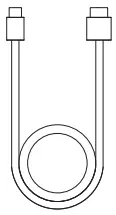
- Two power supply modes: Type-C power supply or 2 pieces AA size batteries (not included)
(Note: as the max. support frequency is 514MHz-596MHz which includes the 96 wireless channel’s frequency, there are parts of frequency may not be utilized.)
Names of Parts
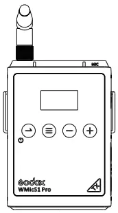
Transmitter (TX)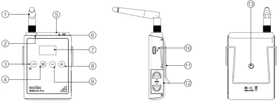
- Antenna
- Power Indicator
- Green light: full battery level
- Red light: Low battery level, replace the batteries
3. Power Source/Mute Button - Long press to power on/off
- Short press to turn Mute mode on or off
- Power Source/Mute Button
- Long press to power on/off
- Short press to turn Mute mode on or off
- Menu Button
- Microphone Input Port
- Audio Indicator
- Green light: Pick-up Sound mode
- Red light: Silent mode
- OLED Display
- Menu +
- Menu –
- USB Type-C Port
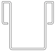
- Metal Clip Port
- Battery Holder
- 2×AA Battery
- 1/4″Shoe Mount Port
OLED Display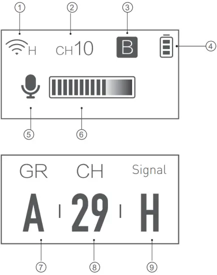
- Transmitter Power
- Transmitter Channel
- Wireless Group
- Battery Level Indicator
- Pick-up Sound/Mute Icon
- Input Volume Indicator
- Transmitter Group A/B
- Transmitter Channel 01-48
- Transmitter Power L/H
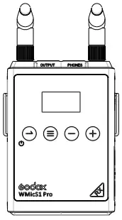
Receiver (RX1)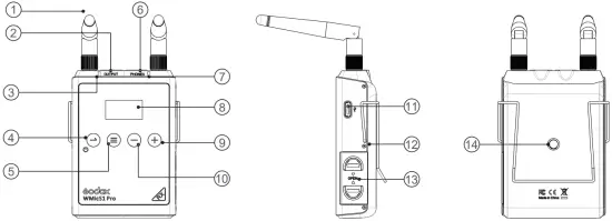
- Antenna
- 3.5mm Audio Output Port
- Power Indicator
- Green light: full battery level
- Red light: Low battery level, replace the batteries
- Power Source/Return Button
- Menu Button
- 3.5mm Earphone Monitoring Port
- RF Indicator
- Green light: Strong RF signal
- Red light: Week or disconnected RF signal
- OLED Display
- Menu + button
- Menu – button
- USB Type-C Port
- Metal Clip Port
- Battery Holder
- 2×AA Battery
- 1/4″Shoe Mount Port
OLED Display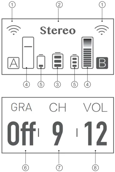
- A/B Group Frequency Signal (indicate Disconnection)
- Mono/Stereo Mode
- A/B Transmitter Battery Level Indicator
- A/B Transmitter Input Volume
- Receiver Battery Indicator
- A/B Group Frequency Signal On/Off
- Receive Channel 01-48
- Output Volume 00-15
Included Item
- Transmitter

- Receiver
- Belt Clip

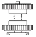
- 1/4″Shoe Mount Adapter

- USB to Type-C Cable

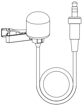
- Omnidirectional Lavalier Microphone LMS-12B AXL

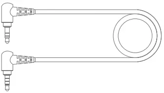
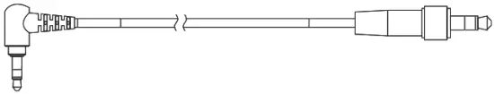
- 3.5mm TRS-TRRS Audio Connect Cable

- 3.5mm TRS-TRS Audio Connect Cable

- XLR To 3.5mm Audio Cable

| Name | Model | Included Items | |
| Transmitter | WMicS1 Pro TX | WMicS1 Pro TX x1 Omnidirectional Lavalier Microphone LMS-12B AXL×1 USB to Type-C Cable ×1 | Belt Clip x1 |
| Receiver | WMicS1 Pro RX | WMicS1 Pro RX x1 3.5mm TRS-TRS Audio Connect Cable ×1×1 XLR To 3.5mm Audio Cable×1 1/4″Shoe Mount Adapter x1 3.5mm TRS-TRRS Audio Connect Cable x1 USB to Type-C Cable ×1 | Belt Clip x1 |
| Metal UHF Wireless Microphone System Kit 1 | WMicS1 Pro Kit 1 | WMicS1 Pro TX x1 Omnidirectional Lavalier Microphone LMS-12B AXL ×1 3.5mm TRS-TRS Audio Connect Cable ×1×1 XLR To 3.5mm Audio Cable×1 1/4″Shoe Mount Adapter x1 3.5mm TRS-TRRS Audio Connect Cable x1 USB to Type-C Cable ×2 | WMicS1 Pro RX x1 Belt Clip x2 |
| Metal UHF Wireless Microphone System Kit 2 | WMicS1 Pro Kit 2 | WMicS1 Pro TX x2 Omnidirectional Lavalier Microphone LMS-12B AXL×2 3.5mm TRS-TRS Audio Connect Cable ×1×1 XLR To 3.5mm Audio Cable×1 1/4″Shoe Mount Adapter×1 3.5mm TRS-TRRS Audio Connect Cable x1 USB to Type-C Cable ×2 | WMicS1 Pro RX x1 Belt Clip x3 |
Note: Packing lists of all models also include the instruction manual(with warranty).
Optional Items (Sold Separately)
- Wireless Handheld Microphone Transmitter WH-M1

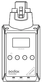
- Plug-On XLR Transmitter TX3-XLR


Power Supply
There are two modes of power supply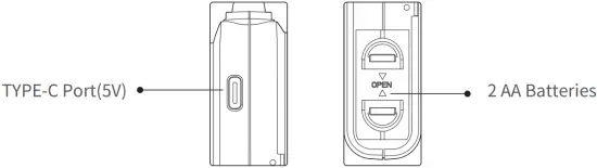
Operation Instruction
Transmitter Setting
![]() Power/Mute Button
Power/Mute Button
Power ON/OFF: Long press this button for 2 seconds to power on/off.
Mute Mode: Short press this button to turn on/off mute mode.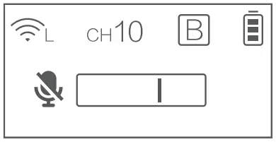
Language Setting: After the first power-on, the language selection is displayed, English/Chinese, press + /- to select, and then press the Menu ![]() button to confirm and exit.
button to confirm and exit.
Note: After selecting the language, if you need to switch the language, you can reset it and select again. Long press the + and – buttons at same time, this operation will reset the device.
Select English language, the operation is following:
![]() Menu Button: Group/Channel/Power settings: long press the menu button to enter the setting interface. Then short press the menu button to switch the next setting.
Menu Button: Group/Channel/Power settings: long press the menu button to enter the setting interface. Then short press the menu button to switch the next setting.
Note: When the group, channel and power are successfully set, short press the menu button won’t change, please long press to enter the setting interface again.
Group Setting: Select the GR (the letters under the GR blinking), press +/- button to select the A/B group, after selecting, short press the menu button to exit and switch to the next setting.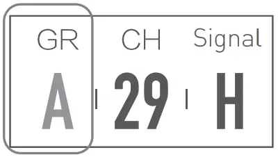
Channel Setting: Select the CH (the number under CH blinking) press the +/- button to set the channel from 01 to 48, then press the menu button to exit and switch to the next setting.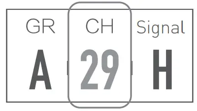
RF Power Setting: Select the (the letter under Signal blinking ), press +/- to switch H(high) and L(low), then short press the menu button to exit.
Note: When the group, channel and power are successfully set, short press the menu button and there is figure blinking, please long press to enter the setting interface again.
Display Brightness Setting: short press +/- button until OLED Light is displayed. Then, long press the menu button until the figure under OLED Light is blinking, and then short press +/- button to choose brightness from 1 to 8 levels.
Firmware Version: short press +/- button until Version is displayed, and this is the version of firmware.
Backlighting Time: Short press +/- button until Screen Dormancy is displayed. Then,long press the menu button until the figures under th Screen Dormancy is blinking. Short press the +/-button to choose backlighting time: ON means with backlighting on, OFF means backlighting off, 10S/30S/60S means delay 10S/30S/60S.
Reset: short press the + and – button at same time for 3 seconds, then Reset… is displayed which means the device is in the progress of reset. After reset, the device back to language selection page and short press +/- button to select, then press MENU button to return to the main interface.
Receiver Setting
![]() Power/Return Button
Power/Return Button
Power ON/OFF: Long press this button for 2 seconds to power on/off. Short press this button to back to main page.
Language Setting: After the first power-on, the language selection is displayed, English/Chinese, press + /- to select, and then press the Menu ![]() button to confirm and exit.
button to confirm and exit.
Note: After selecting the language, if you need to switch the language, you can reset it and select again. Long press the + and – buttons at same time, this operation will reset the device.
Select English language, the operation is following: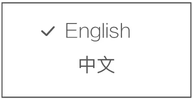
![]() Menu Button: Group/Channel/Volume settings: long press the menu button to enter the setting interface. Then short press the menu button to switch the next setting.
Menu Button: Group/Channel/Volume settings: long press the menu button to enter the setting interface. Then short press the menu button to switch the next setting.
Note: When the group, channel and power are successfully set, short press the menu button and there is figure blinking, please long press to enter the setting interface again.
Group A/B Settings: Long press menu button, GRA displayed, it is settings of group A.
When setting the Group B Settings: first short press the ![]() to return main page and short press +/- button until the GRB displayed, then long press menu button to enter the settings of group B.
to return main page and short press +/- button until the GRB displayed, then long press menu button to enter the settings of group B.
Note: Please set the receiver and transmitter to the same channel during usage, thus achieving recording and real-time monitoring.
Group A/B ON/OFF: Select the GRA/GRB (the letters under the GRA/B blinking), press +/- button to select the ON/OFF, after selecting, short press the menu button to exit and switch to the next setting.
Channel Setting: Select the CH (the number under CH blinking) press the +/- button to set the channel from 01 to 48, then press the menu button to exit and switch to the next setting.
Volume Setting: Select the VOL (the number under VOL blinking) press the +/- button to set the channel from 00 to 15, then press the menu button to exit and switch to the next setting.
Mono/Stereo Output Selection: short press +/- button until Output Mode is displayed. Then, long press the menu button until the Mono/Stereo under Output Mode Light is blinking, and then short press+/- button to switch Mono and Stereo.
Display Brightness Setting: short press +/- button until OLED Light is displayed. Then, long press the menu button until the figure under OLED Light is blinking, and then short press +/- button to choose brightness from 1 to 8 levels.
Firmware Version: short press +/- button until Version is displayed, and this is the version of firmware.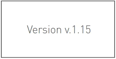
Backlighting Time: Short press +/- button until Screen Dormancy is displayed. Then,long press the menu button until the figures under th Screen Dormancy is blinking. Short press the +/-button to choose backlighting time: ON means with backlighting on, OFF means backlighting off, 10S/30S/60S means delay 10S/30S/60S.
Reset: short press the + and – button at same time for 3 seconds, then Reset… is displayed which means the device is in the progress of reset. After reset, the device back to language selection page and short press +/- button to select, then press MENU button to return to the main interface.
Transmitter Port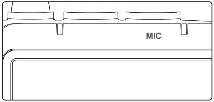
MIC: to connect with lavalier microphone.
Receiver Port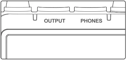
OUTPUT: to connect with external audio signal output.
PHONES: to connect with earphone cable.
Operation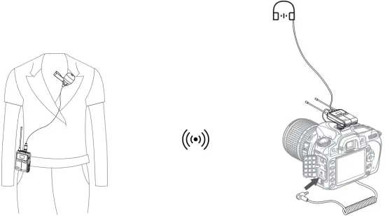
Transmitter
- Insert the omnidirectional lavalier microphone into the transmitter’s MIC port.
- Turn on the transmitter to set the relevant parameters.
- Clip the transmitter onto the belt or put it into your pocket.
Receiver
- Connect the 1/4” cold shoe onto the receiver, and install them on the camera or shooting equipment.
- Insert one end of the 3.5mm cable into the receiver’s OUTPUT port and the other end into camera’s MIC port.
- Turn on the receiver to set relevant parameters.
Note: Please set the group and channels of transmitter and receiver to the same when setting parameters. When a receiver is connecting to two transmitters, A transmitter must be set and used in A group while B transmitter must be set and used in B group.
Technical Data
Name | Body-pack Transmitter TX1 | Portable Receiver RX1 | |
| Model | WMicS1 Pro TX | WMicS1 Pro RX | |
Channel Group | A/B | A/B | |
| Selectable Channel | 96(Group A: 48; Group B: 48) | 96(Group A: 48; Group B: 48) | |
RF Frequency Range | 514MHz – 596MHz | 514MHz – 596MHz | |
| Oscillator Type | Crystal Controlled PLL Synthesizer | Crystal Controlled PLL Synthesizer | |
Audio Frequency Range | 50Hz-20KHz | 50Hz-20KHz | |
| Sound Delay | 12ms | 12ms | |
Antenna (Fold 90°, rotate 360 °) | 1/4λ | 1/4λ | |
| Audio Input Port | 3.5mm Port | 3.5mm Port | |
Power Supply | USB Type-C | 5V 0.2A | 5V 0.2A |
Battery | Two AA batteries | Two AA batteries | |
| Working Temperature Range | 0℃-50℃ | 0℃-50℃ | |
Signal Noise Ratio | ≈70dB | ≈70dB | |
| Receive Sensitivity | \ | -47dBV | |
Distortion | \ | Below 0.5% | |
| Material | Metal | Metal | |
Size | 63*21*198 mm | 63*24*198 mm | |
| Net Weight | 212 g | 226 g | |
Troubleshooting
- Unable to receive audio signal. Make sure batteries are installed correctly and Power
- Switch is turned on. Check if the transmitter and the receiver are set to the same channel, if the microphone or earphone is well connected, or if the devices are set to the correct mode.
- Check if the transmitter is set to silent mode or not.
- Signal disturbance or shooting interference. Change a different channel of the transmitter and receiver.
- Operating audio distance limited or signal missing. Check if batteries are exhausted. If so, replace them.
Maintenance
Avoid sudden drops. The device may fail to work after strong shocks, impacts, or excess stress.
Keep dry. The product isn’t water-proof. Malfunction, rust, and corrosion may occur and go beyond repair if soaked in water or exposed to high humidity.
Avoid sudden temperature changes. Condensation happens if sudden temperature changes such as the circumstance when taking the transmitter and receiver out of a building with higher temperature to outside in winter. Please put the transmitter and receiver in a handbag or plastic bag beforehand.
Keep away from strong magnetic field. The strong static or magnetic field produced by devices such as radio transmitters leads to malfunction.
This product, except consumables e.g. lapel microphone, is supported with a one-year warranty.
Unauthorized service will void the warranty.
If the product had failures or was wetted, do not use it until it is repaired by professionals.
Changes made to the specifications or designs may not be reflected in this manual.
Declaration of Conformity
GODOX Photo Equipment Co,Ltd. hereby declares that the This equipment are in compliance with the essential requirements and other relevant provisions of EU Directive 2014/53/EU. They are allowed to be used in all EU member states.

For more information of DoC, Please click this web link:http://www.godox.com/DOC/Godox_WMicS1Pro_DOC.pdf-
FCC Caution
This device complies with part 15 of the FCC Rules. Operation is subject to the following two conditions:
- This device may not cause harmful interference, and
- this device must accept any interference received, including interference that may cause undesired operation.
Any Changes or modifications not expressly approved by the party responsible for compliance could void the user’s authority to operate the equipment.
Note: This equipment has been tested and found to comply with the limits for a Class B digital device, pursuant to part 15 of the FCC Rules. These limits are designed to provide reasonable protection against harmful interference in a residential installation. This equipment generates uses and can radiate radio frequency energy and, if not installed and used in accordance with the instructions, may cause harmful interference to radio communications. However, there is no guarantee that interference will not occur in a particular installation. If this equipment does cause harmful interference to radio or television reception, which can be determined by turning the equipment off and on, the user is encouraged to try to correct the interference by one or more of the following measures:
- Reorient or relocate the receiving antenna.
- Increase the separation between the equipment and receiver.
- Connect the equipment into an outlet on a circuit different from that to which the receiver is connected.
- Consult the dealer or an experienced radio/TV technician for help.
The device has been evaluated to meet general RF exposure requirement.
Warranty
Dear customers, as this warranty card is an important certificate to apply for our maintenance service, please fill in the following form in coordination with the seller and safe keep it. Thank you!
| Product Information | Model | Product Code Number |
| Customer Information | Name | Contact Number |
| Address | ||
| Seller Information | Name | |
| Contact Number | ||
| Address | ||
| Date of Sale | ||
| Note | ||
Applicable Products
The document applies to the products listed on the Product Maintenance information (see below for further information). Other products or accessories (e.g. promotional items,giveaways and additional accessories attached,etc.) are not included in this warranty scope.
Warranty Period
The warranty period of products and accessories is implemented according to the relevant Product Maintenance Information. The warranty period is calculated from the day(purchase date) when the product is bought for the first time,and the purchase date is considered as the date registered on the warranty card when buying the product.
How to Get the Maintenance Service
If maintenance service is needed, you can directly contact the product distributor or authorized service institutions. You can also contact the Godox after-sale service call and we will offer you service. When applying for maintenance service, you should provide valid warranty card. If you cannot provide valid warranty card, we may offer you maintenance service once confirmed that the product or accessory is involved in the maintenance scope, but that shall not be considered as our obligation.
Inapplicable Cases
The guarantee and service offered by this document are not applicable in the following cases:
- The product or accessory has expired its warranty period;
- Breakage or damage caused by inappropriate usage, maintenance or preservation, such as improper packing, improper usage, improper plugging in/out external equipment, falling off or squeezing by external force, contacting or exposing to the improper temperature, solvent, acid, base, flooding and damp environments, etc;
- Breakage or damage caused by non authorized institution or staff in the process of installation, maintenance, alternation, addition and detachment;
- The original identifying information of product or accessory is modified, alternated, or removed;
- No valid warranty card;
- Breakage or damage caused by using illegally authorized, nonstandard or non-public released software;
- Breakage or damage caused by force majeure or accident;
- Breakage or damage that could not be attributed to the product itself. Once met these situations above, you should seek solutions from the related responsible parties and Godox assumes no responsibility. The damage caused by parts, accessories and software that beyond the warranty period or scope is not included in our maintenance scope. The normal discoloration, abrasion and consumption are not the breakage within the maintenance scope.
Maintenance and Service Support Information
The warranty period and service types of products are implemented according to the following Product Maintenance Information:
| Product Type | Name | Maintenance Period(month) | Warranty Service Type |
| Parts | Product Main Body | 12 | Customer sends the product to designated site |
| Battery | 3 | Customer sends the product to designated site | |
| Charger, Power Cable,Sync Cable, Electrical Parts etc. | 12 | Customer sends the product to designated site | |
| Other Items | Battery Case, Windscreen Foam, Wind Cap, Locking Device, Lanyard, Tie, Velcro Tape, Clip, Bag, Package etc. | No | Without warranty |
CUSTOMER SUPPORT
Godox After-sale Service Call 0755-29609320-8062
GODOX Photo Equipment Co., Ltd.
Add: Building 2, Yaochuan Industrial Zone,Tangwei Community, Fuhai Street,
Bao’an District, Shenzhen 518103, China
Tel: +86-755-29609320(8062)
Fax: +86-755-25723423
E-mail: [email protected]