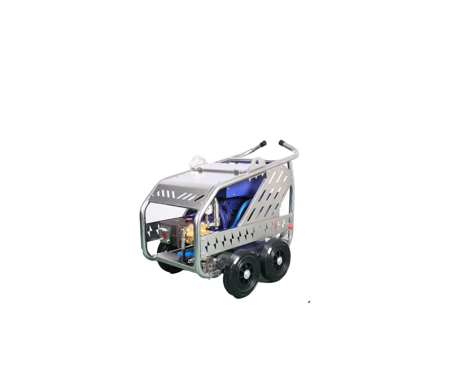
SAMPSONE SMP5021D High-Pressure Water Jet
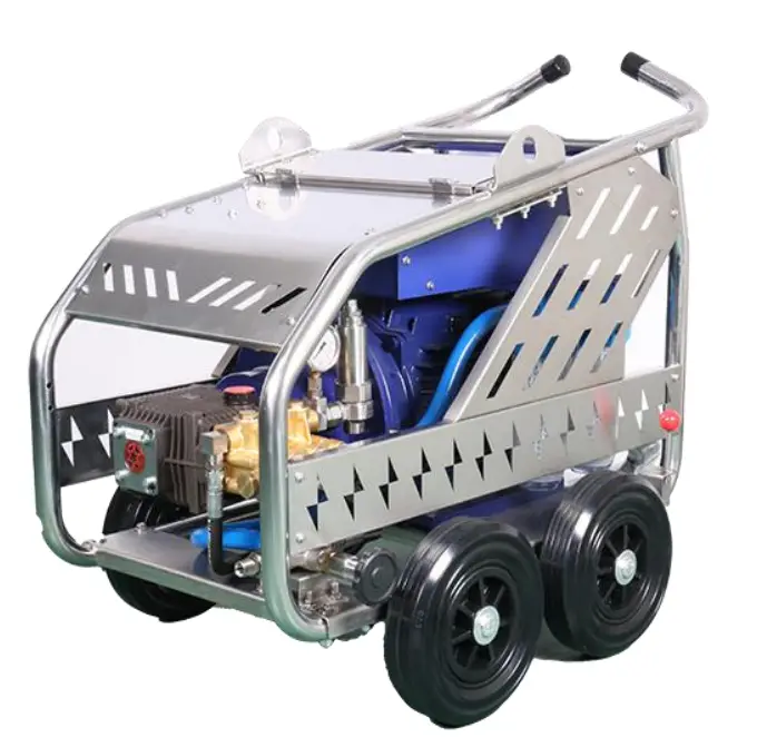
Intoroduction
In order to operate this machine correctly and for your safety, please carefully read this User and Parts Manual in advance.
wisent offers one year’s warranty, but it is only limited to there placement or repair of faulty items caused during the manufacture. If the defects or damage are caused by the misuse of customers, wisent has no responsibility or liability for providing free replacement or repair.
| TYPE | SMP 5021 |
| Working pressure | 500bar/7250psi |
| Flow rate | 18.51pm/4.9gpm |
| Motor protection | IP 55/Class F |
| Motor capacity | 22KW/29HP |
| Power supply | 440v/60hz/4phase |
| Dimensions | 46X 29 X37 in. |
| Weight | 7261bs |
WARNINGS
- Please read this manual carefully before you start.
- Always keep in mind that the high-pressure water jet is very dangerous, so do not direct the nozzle at any people or animals.
- It is highly recommended to use this appliance outdoors only. If it must be used indoors, make sure that the area is well-ventilated and spacious.
- When operating this machine, it must be grounded to protect the user from electric shock effectively.
- Two people are suggested for the operation of this machine.
- After finish cleaning work, electricity and water should be disconnected.
- Before you begin: check the oil level and replace the oil cap. Change the lubrication oil (full-synthetic oil) after first the 30 hours’ work and then change the oil every 500 hours.
- Check the status of this machine before operation every time. Do not use it if any critical parts such as cords, pressure gauge, or trigger gun are damaged.
- The operator must wear protective gear including helmet, visor, ear muffs, overall, gloves and boots.
- Do not use acid materials, gasoline, or other flammable materials to clean this machine. Use the household detergent only.
- When operating this machine, other people should keep a safe distance unless they wear protective gear. The safe distance is Sm.
- Be alert to ricocheting parts. it also can hurt you, so wear protective clothing all the time.
- Do not touch the power supply, the plug, the wires, and other electric devices with wet hands.
- This machine was tested in our factory, so it is normal that there is some water left inside it.
- The water jet is under high pressure. When switching on the machine, hold the gun firmly and be prepared to take the kickback pressure.
- Use only high-pressure hoses, nozzles, cables, fittings, and couplings that are provided with this machine or recommended by the manufacturer. Protect them from any damage.
- Whenever the operator leaves this machine, even temporarily, switch it off.
- Do not operate it when you are drunk, sleepy, or not familiar with it. This machine is intended for non-disabled persons (excluding children). Keep it away from children.
- When winding the hose, make sure the machine has been turned off and the pressure in the hose has been released.
- Prevent fire and explosion. Shut down the motor before filling the pump with oil. When using the machine, keep it away from fuels. Do not spray flammable liquids.
- Use only the spare parts provided by the manufacturer. It is strongly suggested to keep more spare parts when using onboard than using onshore.
- Do not use it to clean clothes or footwear, especially when they are being worn.
- During maintenance, such as cleaning or replacing spare parts, the power supply should be disconnected.
- If the cord needs to be extended, must use a watertight plug and socket.
- If the power supply runs out when the machine is running, switch off themachine.
- Before functioning, check if the machine is positioned on a horizontal base. Please note that the base must be horizontal and stable.
- Prevent the appliance from slipping or moving when operating it. Engage the built-in brake of the caster before connect it to the power supply.
EMERGENCY INFORMATION
Operating this machine is a dangerous job. It is essential to give immediate medical attention to personnel who operate this cleaner when injuries happen. In this case, it will be very beneficial to let the medical personnel know all the facts that are related to such injuries. It is suggested that the following medical alert tag should be provided to the operating personnel. It describes the nature of their work and possible injuries. This tag should be printed and carried by the personnel.
![]() Medical Alert
Medical Alert
This card is for the operati ng personnel who are subject to injuries. Immediate medica l treatment is very essent ial for any accidents.
The facts that are related to t his person’s job are: This person has been working with a high pressure water jet cleaner and the highest pressure is up to 60Mpa. The highest water speed is around 1000mps. A local medical center should be contacted immediately for further treatment.
PERSONAL PROTECTIVE EQUIPMENT SUGGESTION
Due to the high pressure caused by this machine, professional equipment should be provided to the operating personnel. Never start the machine unless the following protection gear has been worn.
 | Protective clothing | It is recommended to wear protective clothing that can withstand high pressure, not just waterproof. they must take care never to point the gun at themselves even the operators are wearing protective clothing. |
 | Eye protection | Visor and goggles are very important for operators because they can protect the operators from being injured by spray and flying debris. |
 | Hearing protection | The noise caused by this machine is harmful to operators, so always wearing ear muffs is recommended, especially when they have to work for a long time. |
 | Head protection | The operators must wear a safety helmet all the time. The helmet must be able to withstand high-pressure water jet up to 50 Mpa. |
 | Hand protection | Gloves that can withstand high pressure must be worn all the time. The outer surface is non-slip designed is preferable. |
 | Foot protection | Safety boots must contain steel toecaps. The length that the steel toecaps cover must be not less than 30% of the whole footwear length. |
SET-UP AND USE
Place this machine in a horizontal and safe location, and then engage the built-in brake on the caster wheel. Then follow these steps to use this machine.

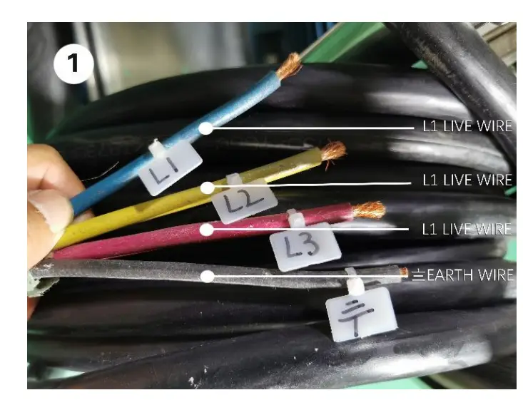
- Connect the power cable plug to a 380v or 440v power socket. The power socket should be grounded. Please note that it is very important to make sure that the machine has been grounded before switch on it. The black line is the earth line.

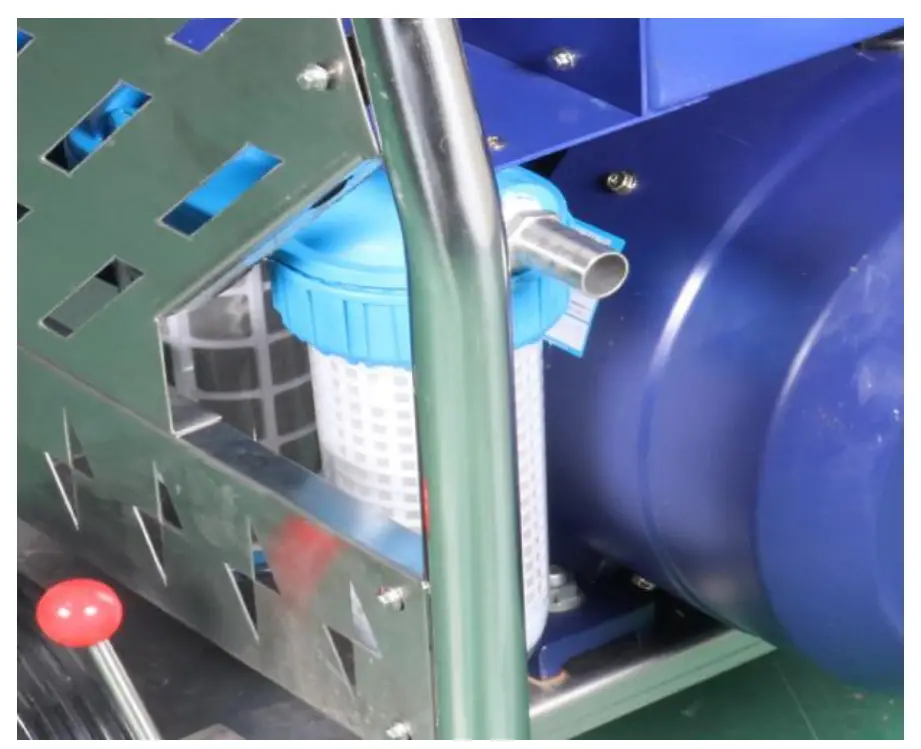
When using additional cords, the plugs and sockets must be watertight. The following guidelines are useful when the extension of power wire is needed.Length of cable (m) Size of cable (G x mm) 100-200 4 X 16 50-100 4 X 10 0-50 4×6 - Connect the freshwater supply by attaching a hose to the inlet of the filter. Please note that the inlet is low-pressure. Do not confuse the inlet and the outlet.

When using the water supply from the water main, connect a supply hose to the water main and then open the water supply. If this machine must be connected to potable water mains, make sure that the water main is separated by a backflow preventer.
Please note that the delivery of the water main must be at least twice the maximum pump flow. For this machine, the recommended minimum delivery rate of the water main is 30LPM.
It is better to place the cleaner as near to the water mains as possible. This can ensure enough water supply.
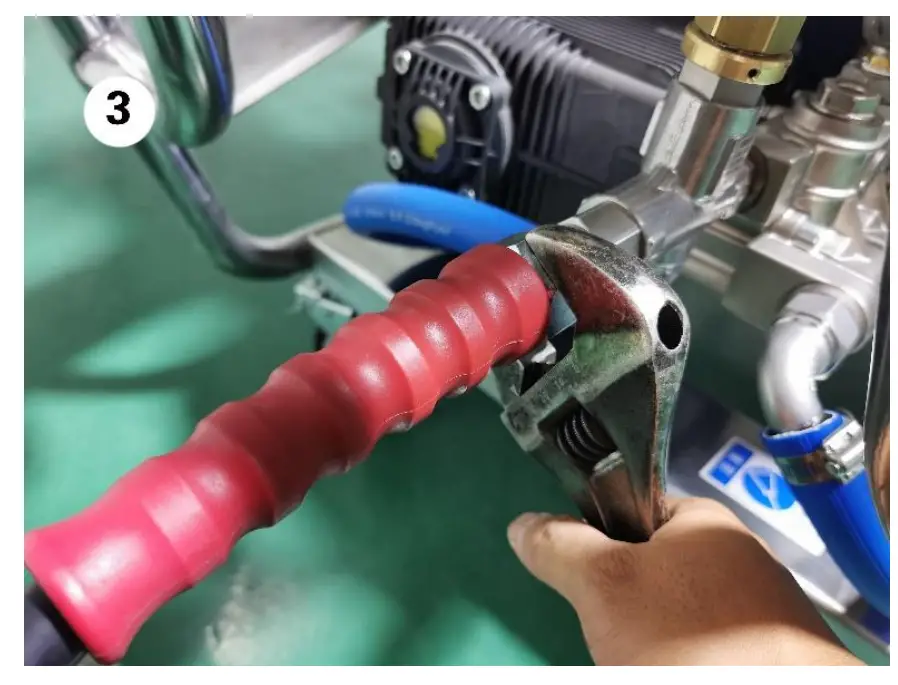
If the appliance is connected to a water supply that is from an open container, please follow the steps below. First, unscrew the high-pressure hose at the high-pressure end of the pump. Then, turn on this machine and run it for a while until there are no water bubbles at the outlet. Lastly, switch off this machine and screw on the hose at the high-pressure end again. These steps must be repeated if the machine is inactive for a certain period. These steps are crucial because the machine may be damaged by the air inside the inlet hose. - Connect the high-pressure hose. Mount the high-pressure hose to the outlet of the pump head, then use a wrench to tighten the connection. If additional high-pressure hoses are needed, use nipples male-male to connect them.

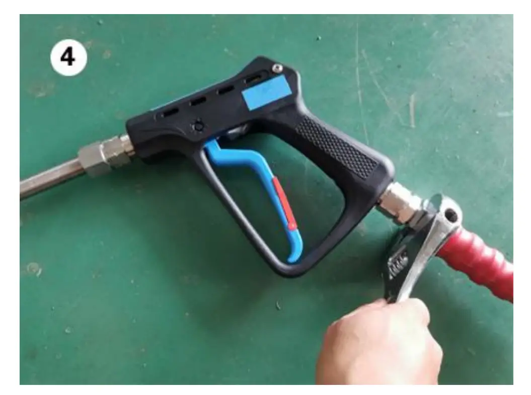
- Connect the gun. The gun has been equipped with a lance. Mount the trigger gun with the lance to the high-pressure hose. Use wrenches to tighten their connection.

- At last mount a correct nozzle at the lance’s end. For different work, there is a range of nozzles that can be chosen.

- Start the operation. Now the machine is ready for operation. First, make sure that the water supply is open. Then switch on the main power. Once press the START button, the machine will start. There is a handle on both trigger gun and lance. Please hold them firmly. When pressing the trigger, the blasting will start
(Note: Always keep in mind that Do not direct the gun at other people. Do not let the machine run idle more than 10 minutes because the machine may be damaged by the heated water.). - Shut down the machine. After finish the work, press the STOP button, then the machine will stop. Keep pressing the trigger to release the pressure inside the hose. At last, turn off the water supply.
- Store this machine. Unwind the hoses and the cords. Unscrew the nozzle. Put them as well as the gun in a safe place. Store this machine under a shield. If it is used on board, position it on the poop deck or behind the superstructure.
MAINTENANCE
For the safe and lasting use of this machine, it is very important to do daily inspections from time to time. The items that should be checked include but not limited to the following:
Check the oil level in the pump’s crankcase. Fill it up if necessary. Change the lubrication oil (full-synthetic oil) after the first 30 hours’ work and then change the oil every 500 hours. The recommended oils are SAE 30, lSW-40, 20W-40.

Check the high-pressure hoses. Replace them if they have cracks.
Check the strainer. Clean it if necessary. This can avoid damage to the pump.
Check if there are air bubbles in the suction hose. Tighten the hose clips if bubbles are found between the water supply and the pump.
Check leakage, especially from the high-pressure connections. If there is leakage, stop the machine, release the pressure, and then tighten the connections.
Check the air intake grill of the motor. Clean it if necessary.
Check the wires. If wear or cracks are found, replace them.
Check the spray nozzle. Replace the nozzles when there are cracks on them or the pressure drops below the normal values. It is recommended to store some spare nozzles because they may be damaged by accidental collision.
Descaling must be carried out periodically, and this operation must be carried out by our after-sales service. Must use the specific descaling products since other inappropriate products may cause wear of the components. The interval of descaling depends on the water quality used and the frequency of use.
Frequent cleaning can keep the machine in good working conditions. Do not use acid materials, gasoline, or other flammable materials to clean this machine. Use the household detergent only. Never clean the machine itself with the high-pressure jet.
Storage for long periods. If this machine is left unused for long periods, it should be shielded against damage. Before storage, use non-alcoholic antifreeze products to flush the pump thoroughly.
When filling the pump with anti-corrosion emulsion, operate as the following steps.
Prepare a diaphragm pump.
Clean the connection pipe and connect it to the high-pressure outlet port.
Connect a suction hose to the diaphragm pump. The other end of the suction hose is connected to the cleaner’s pump suction end.
Fill the container with anti-corrosion emulsion. Before filling, close it if open.
Put both the free ends of the suction pipe and the high-pressure pipe into the container.
Start up the diaphragm pump.
Keep running the pump until there is anti-corrosion emulsion coming out of the high-pressure pipe.
Run the diaphragm pump for another minute.
Switch off the diaphragm pump and remove the pipe from the suction end. Close it with a plug.
Remove the pipe from the high-pressure end and plug it.
Storage of the pipes. Dry the connections by compressed air. Apply polyethylene to their surfaces. Do not wind them too tightly. Do not fold them.
Restart after inactivity of long periods. Before turn on this machine after a long period of storage, check the oil level and the conditions of other important parts such as cords, high-pressure hoses, the gun, and valves.
During the periods when there is a freezing risk, do not use this unit and keep it in a safe place. Remember that if it operates when the weather is very cold, serious damage may be caused to the pump.
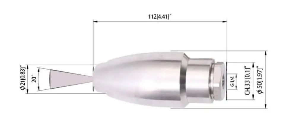
HIGH-PRESSURE NOZZLE
The high-pressure nozzle is one of the most important parts of this machine. It can produce more powerful water jet than normal nozzles. Its dimensions and technical specifications are shown below.
| CODICE CODE | FATTORE DI Prolacta Capacitor SIZE |
| 25.1460.20 | 02 |
| 25.1460.30 | 03 |
| 25.1460.35 | 035 |
| 25.1460.40 | 04 |
| COOICE COOE | FATTORIE Dill PORTATA Cavalry SIZE |
| 25.1460.50 | 05 |
| 25.1460.60 | 06 |
| 25.1460.65 | 065 |
| 25.1460.70 | 07 |
| 25.1460.80 | 08 |
| – PRESSIONE NOMINALE RATED PRESSURE | 600 bar – 60 MPa (8700 psi) |
| – PRESSIONE MINIMA DI UTLIZZO MIN . OPERATING PRESSURE | 180 bar – 18 MPa (2600 psi) |
| PORTATAMINIMA MIN . FLOW RATE | 6.2 Umin (1.6 USGp.m.) 180 bar – 18 MPa (2600 psi) ugello (nozzle) 02 |
| -PORTATA MASSIMA MAX FLOW RATE | 44.6 Umin (11.8 USGp.m.) 600 bar – 60 MPa (8700 psi) ugello (nozzle) 08 |
| – TEMPERATURA MINIMA MIN WORKING TEMPERATURE | 5° c (41° F) |
| – TEMPERATURA MASSIMA MAX WORKING TEMPERATURE | 90 ° C (195° F) |
| -MASSA WEIGHT | 540 g (19 oz.) |
PROCEDURE FOR USING A ROTATING NOZZLE
The operators should pay attention to the correct procedure for operating the rotating nozzle. Please read the following introduction carefully before you start since the wrong operation may cause incidents.
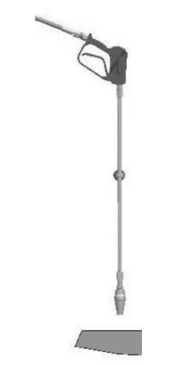
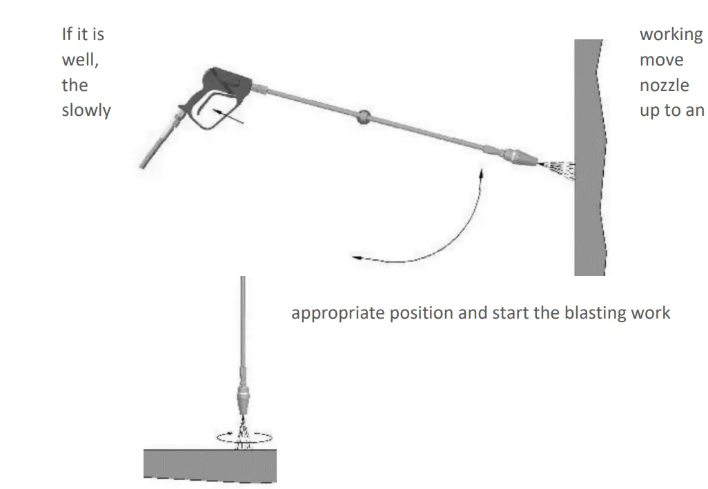
First, hold the gun upright and make the nozzle facing down. If it is well, the slowly
Then, press the trigger and observe the nozzle’s working state.
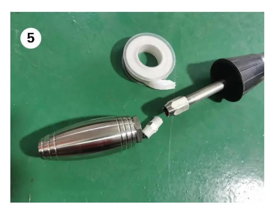
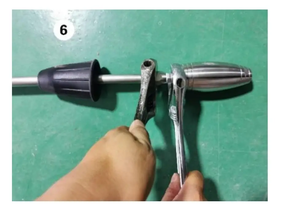
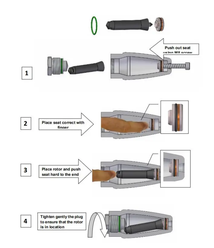
REPAIR PROCEDURE FOR ROTATING NOZZLE
WET SANDBLASTING ACCESSORY (OPTIONAL)
BEFORE YOU BEGIN
- Always point the sand nozzle downward before the operation because this can avoid the water entering the sand supply.
- Make sure that the sand hose is always dry before using it.
- Keep in mind that the sand should not be wet during the operation, so the sand should be covered to prevent the overspray from wetting the sand.
- Be careful not to let small pieces of paper or other foreign bodies enter the sand. The invasion of impurities could block the flow of the sand.
- Do not change any part of this equipment.
- Stop the machine first when you want to disassemble the accessories.
OPERATION
a) Locate the sand container at a safe location that is away from water and other impurities.
b) Put the sand probe into the sand container.
c) Attach a quick-connection nozzle to the gun’s lance.
d) Connect the sandblaster to the end of the lance.
e) Turn on the water supply and release the air left in the system by triggering the gun.
f) Start the machine by following the above-mentioned instructions.
g) Change the lance’s angles and distances from the workpiece and make yourself comfortable with the sandblaster.
h) At last, you can start your work.
MACHINE TROUBLESHOOTING & REPAIR
| Malfunction | Troubleshooting | Repair |
| The machine does not start working when pressing the START button | The power supply went off | Seek help from the organization or person who is in charge of the power supply. |
| The plug is loose. | Insert the plug into the socket properly. | |
| The pump is stuck | Try it again. If the problem persists, contact the manufacturer. | |
| The voltage of power mains is too low. | Change the power supply or check the power mains’ stability. | |
| The pressure is lower than normal pressure | Regulator valve is set on minimum | Increase the pressure by adjusting the pressure regulator knob. |
| The water supply is insufficient. | Make sure that the water supply is at least 30% higher than the delivery rate stated on the nameplate. | |
| The filter is clogged. | Clean the filter. | |
| The nozzle is broken or worn out. | Replace the nozzle. | |
| Inlet or outlet valves are clogged | Seek help from the manufacturer. | |
| The pressure fluctuates. | Gaskets are worn. | Seek help from the manufacturer. |
| The filter is dirty. | Clean the filter. | |
| Valves are clogged or worn out. | Seek help from the manufacturer. | |
| The nozzle is broken or worn out. | Replace the nozzle. | |
| The machine stops suddenly. | The plug is loose. | Check the connection between the plug and the socket. |
| Earth leakage circuit breaker is triggered. | Check the circuit. | |
| Water shortages protection is triggered. | Check the water supply. |
| Overcurrent protection is triggered. | Check the circuit. | |
| Overload protection is triggered. | Check the working state of the pump. | |
| The noise is abnormal. | Valves are clogged. | Seek help from the manufacturer. |
| The filter is clogged. | Clean the filter. | |
| The water temperature is very high. | Check the water temperature and make sure that the temperature is below 50 degrees. | |
| Bearings are worn. | Seek help from the manufacturer. | |
| There is a water leak. | Water leaks from the gun. | Tighten the connection between different parts of the gun. If the problem persists, contact the manufacturer. |
| Water leaks from the pump. | Contact the manufacturer. | |
| Water leaks from the hose. | Tighten the connections between different parts. | |
| Water leaks from valves. | Contact the manufacturer. | |
| There is water in the oil. | 0-rings are worn. | Contact the manufacturer. |
WARRANTY CONDITIONS
Every product is tested strictly and is covered with a warranty against any defects.
The effective date of the warranty is valid from the first day of purchase.
There are some circumstances in which the warranty will not cover:
Normal wear of parts such as nozzles, hoses, filters, and other consumable accessories.
Damage caused by misuse or inadequate treatment.
Accidental damage caused during transport.
Damage caused by wrong installations.
DISPOSAL
When the machine is discarded, the disposal must be in accordance with local laws. It is also can be disposed of by returning it to the manufacturer. Please note that the disposing of it carelessly in the environment will cause severe damage to the environment.
Do not dispose of it in the urban waste containers.
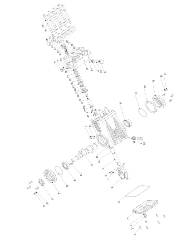
PUMP STRUCTURE
| POS. | PART NO | DESCRIPTI0N | POS. | PART NO | DESCRIPTION |
| l | 590201102 | Hexagon socket head screw | 29 | 501001130 | support ring |
| 2 | 500010003 | 0-ring | 30 | 590104001 | main ·waterleaf |
| 3 | 590101019 | Tanveer head | 31 | 501001270 | main V.‘afterdeal gasket |
| 4 | 301031001 | flack Cover Assembly | 32 | 501001260 | main \Yaterseal spring |
| 5 | 590101017 | 0-ring | 33 | 501001250 | ·water seal spring seat |
| 6 | 501002050 | Connecting Rod Assembly | 34 | 590207101 | Hexagon socket locking screws with flat end |
| 7 | 501002110 | Plunger Pin | 35 | 501001230 | inlet check valve cover |
| 8 | 590206001 | Axle collar | 36 | 501001210 | Inlet Check Valve Spring |
| 9 | 501002100 | plunger | 37 | 501001220 | Inlet Check Valve |
| 10 | 501002070 | oil-free bearing | 38 | 501001240 | inlet one-way seal |
| 11 | 501002010 | crankcase | 39 | 590103008 | Open collar |
| 12 | 501002220 | crankshaft21-N21 | 10 | 590101052 | 0-ring |
| 13 | 500011003 | Flal Key | 41 | 590101065 | 0-ring |
| 11 | 590303001 | Tapered roller bearing | 12 | 590101100 | 0-ring |
| 15 | 590101102 | 0-ring | 43 | 500010002 | Plug Up |
| 16 | 501002030 | Exlcndcd End Flange | 44 | 590101035 | 0-ring |
| 17 | 590108003 | Skeleton Seal | 15 | 501001200 | bonnet |
| 18 | 590204103 | Double-sided Tooth Pad | 46 | 590201033 | Hexagon socket head screw |
| 19 | 590201006 | Ilexagon socket head screw | 47 | 590204101 | Double-sided Tooth Pad |
| 20 | 590107004 | TC4 framework oil seal | 48 | 501001020 | pump head |
| 21 | 501002091 | Support | 49 | 590101025 | 0-ri ng |
| 22 | 501002120 | Baffle | 50 | 301191001 | high pressure check Valve Assembly |
| 23 | 501002160 | DS18 ceramic tube | 51 | 590101033 | 0-ri ng |
| 24 | 501002060 | Ceramic Pipe Lacking llolt | 52 | 501001160 | check valve screw’ |
| 25 | 590101114 | 0-ring | 53 | 501002080 | Clearance Adjustment Gasket |
| 26 | 501001090 | rear guide ring | 54 | 301041001 | Side Cover Assembly |
| 27 | 590101079 | 0-ring | 55 | 101702010 | Oil Plug |
| 28 | 590105002 | Auxiliary water seal | 56 | 301150101 | Bl! Oil Mark Assembly |
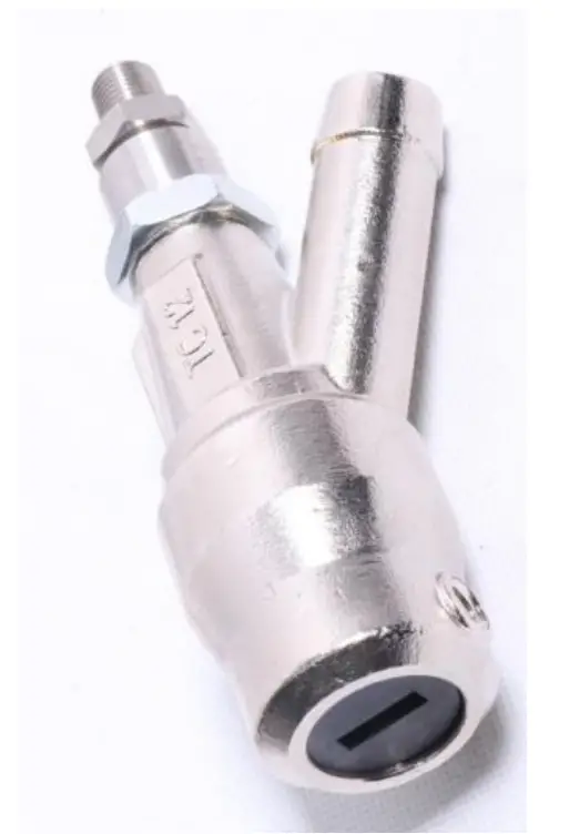
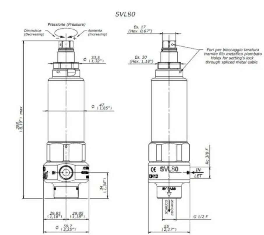
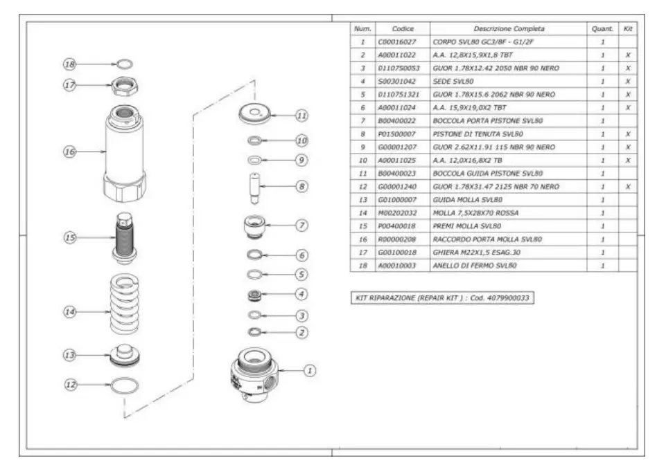
SAFETY VALVE STRUCTURE
PRESSURE REGULATOR STRUCTURE
| Num. | I Description | Quant. I |
| 1 | CORPO VHP60 G1/2F | 1 |
| 2 | GUOR 1.78X15.6 2062 NBR 90 NERO | 1 |
| 3 | SEDE VHP50 | 1 |
| 4 | OTTURATORE DI TENUTA VHP50 – VHP60 | 1 |
| 5 | GUOR 1.78X17.17 2068 NBR 90 NERO | 1 |
| 6 | DISTANZIALE I NF. PER PISTON E VHP50 | 1 |
| 7 | A.A. 10X14,7X1,8 TB | 1 |
| 8 | GUOR 2.62X9 . 92 112 NBR 90 NERO | 1 |
| 9 | GUOR 1. 78X20 .35 2081 NBR 90 NERO | 2 |
| 10 | DISTANZIALE SUP. PER PISTONE VHP50 | 1 |
| 11 | PISTONE VHP50 | 1 |
| 12 | GUOR 2.62X13.95 3056 NBR 90 NERO | 1 |
| 13 | A.A. 14X18,7X1,8 TB | 1 |
| 14 | RACCORDO PISTON E VHP50 | 1 |
| 15 | SFERA 11/32 AIS/440 C GR10 ISO 3290 | 1 |
| 16 | PERNO PORTAMOLLA VHP50 | 1 |
| 17 | MOLLA 5,4X16,6X65 GRIGIO | 1 |
| 18 | GHIERA DI BLOCC. M27X1,25 – VHP60 | 1 |
| 19 | GRANO STE! M4X4P. CON.UNI 5927 Z.B. | 1 |
| 20 | MANOPOLA DI REG. M27X1,25 ESAG. 30 | 1 |
| 21 | GUOR 3.53X7.52 4028 NBR 90 NERO | 1 |
| 22 | OTTURATORE VHP70 | 1 |
| 23 | MOLLA OTTURATORE VHP70 | 1 |
| 24 | A.A. 20,8X23,7X1,4 TBT | 1 |
| 25 | RACCORDO RITEGNO G1/2F VHP70 | 1 |
ROTATING NOZZLE STRUCTURE
| POS. 1 | KIT | DESCRIPTION CASING | QTY 1 |
| 2 | X | SUPPORT RING | 1 |
| 3 | X | O-RING | 1 |
| 4 | X | PICK-UP BEARING | 1 |
| 5 | X | BEARING | 1 |
| 6 | X | NOZZLE | 1 |
| 7 | X | SLEEVE | 1 |
| 8 | X | ROTOR SLEEVE | 1 |
| 9 | X | RECTIFIER | 1 |
| 10 | X | RING | 1 |
| 11 | X | RUNNER | 1 |
| 12 | X | O-RING | 1 |
| 13 | GRUB SCREW NOZZLE | 1 | |
| 14 | DRIVE PLUG | 1 |
GUN STRUCTURE
| Pos. | Caddice | !Descrizione | Q.ta |
| 1 | 30.5815.84 | Tappan G1/4M DIN259 Plats. Nero | 1 |
| 2 | 30.5408.31 | Tappan porta olla | 1 |
| 3 | 10.4041 .00 | Andantes. 19,3x22x1,2 mm PTFE | 1 |
| 4 | 10.3070.02 | An. OR 1,78×18,77 mm Ni 85 | 1 |
| 5 | 10.2027.00 | Guar. stele 10x15x2,2 mm +OR | 5 |
| 6 | 30.4040.31 | An. distensile 10, 1×15,8×3,8 mm ott. | 1 |
| 7 | 30.4042.51 | Mollag 2,4×15,3×30 mm inox | 1 |
| 8 | 30.5411 .24 | Piston+ sede RL84 | 1 |
| 9 | 10.3066.01 | An.OR 1,78×15,6 mm Ni 85 | 1 |
| 10 | 10.4042.00 | An.anties.16,3x19x1 ,2 mm | 1 |
| 11 | 30.4038.31 | Tappo ant. M18x1 ,.5 ott. | 1 |
| 12 | 30.4041.31 | Spina cil. 6×25,8 mm ott. | 1 |
| 13 | 30.5405.35 | Coro RL84 ott. | 1 |
| 14 | 30.5403.51 | Riccardo G1/2″ inox | 1 |
| 15 | 30.1510.84 | Sicora PA rossa | 1 |
| 16 | 30.0674.51 | Leva nera | 1 |
| 17 | 30.0674.51 | Peron di Battuta 8×6,9mm inox | 1 |
| 18 | 30.2517.31 | Spina cil. 5×27,5 mm ott. | 1 |
| 19 | 30.5412.24 | Kit sconce RL 84 + viti | 1 |
| 20 | 16.3075.51 | Viet autofil.3,5×18 mm in. | 7 |
| 21 | 30.5407.56 | Tuba M16Mx1,5M-141,5 mm in. | 1 |
| 22 | 30.5406.51 | Record G1/2″ inox | 1 |
| 23 | 14.3802.00 | Rosetta 12x18x1,5 mm Cu | 2 |
| 24 | 30.5016.569 | Tuba G1/2 MM 390 mm inox (1) ** | 1 |
| 24 | 30.5026.569 | Tuba G1/2 MM 790 mm inox (2) .. | 1 |
| 24 | 30.5037.569 | G1/2 MM 1250mm inox (3) ** | 1 |
| 25 | 30.5017.35 | Support per tuba G1/2″ | 1 |
| 26 | 30.5015.51 | Portaugello G1/2F-1/4F Npt inox | 1 |
| 27 | 13.5305.(l) | Disco 8×1 ,5 Cu | 2 |
| 28 | 11.4627 .00 | Dado es. M1 0 | 1 |
| 29 | 14.3799.00 | Rosetta 10x21x2 mm | 1 |
| 30 | 41.0409.84 | Monopole 32×115 mm PP nero | 1 |
| 31 | 16.2035.00 | Vite DIN933 M10x35 mm zinc. | 1 |
| 32 | 41.0411 .84 | Tappomanopola PPnero | 1 |
| 33 | 30.5018.51 | Nipomo p/ug.inox RL84-RL204 G1/2M … | 1 |
| 34 | 15.3815.00 | Etiquette “56MPa Tubo inox – PA” | 1 |
| 35 | 30.5060.00 | App .spalla -RL600 G1/4 M 300mm ** | 1 |
| 36 | 13.5009.51 | Nipomo G 1/4 M – 1/4 Npt M inox ** | 1 |
ELECTRICAL SCHEMATIC OF THE CONTROL PANEL
PERSONAL PROTECTIVE EQUIPMENT (OPTIONAL)

| No. | Description | Quantity |
| 1 | Protective overall (normal) | Optional |
| 2 | Protective overall (highlight) | Optional |
| 3 | Protective apron | Optional |
| 4 | Protective helmet (with earmuffs, visor) | Optional |
| 5 | Protective boots | Optional |
| 6 | Protective gloves | Optional |