Assembly instructions for Designer Radiators
Please read the instructions carefully, before starting assembly.
– The radiator must be installed by a qualified plumber or another competent specialist.
– Note that the dimensions and panel-/pipe layout of the radiator may differ from the respective illustrations.
– Do not dispose of the packaging until you have secured small parts such as wall brackets and mounting accessories.
– We recommend wearing suitable protective clothing such as gloves and reinforced work shoes for assembly.
Required tools:
(not included in the delivery!)
![]()


Phillips screwdriver Tape measure Drilling machine
![]()
![]()
![]()
Flat screwdriver Wrench Drill bit
1. Determination and scope of use of the products
– The radiators are designed to be used in a closed central heating system.
2. Maximimum operating pressure
– Please note the maximum operating pressure specified in the assembly dimension table. Use above this level can damage the radiator and void any warrantee.
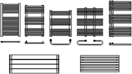
3. Scope of delivery of a standard packaging:
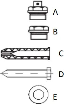
– 1 pc. radiator
– 1 pc. Air vent (A)
– 1 pc. Blanking plug (B)
– 4 pcs. Masonry wall plug(C)
– 4 pcs. Screws (D)
– 4 pcs. Washers (E)
– 4 pcs. Wall bracket
4. General assembly instructions
– Check the contents of the packaging for completeness.
– Make sure that you have the appropriate connection fitting.
– Before drilling the holes, make sure there are no hidden water, electric or gas lines behind the wall.
– The distance between the Floor and the bottom of the radiator should be at least 150 mm so that efficient heating and ventilation is possible.
– Prepare the necessary tools before and make sure that there is enough space and a clean, dry environment for assembly.
– Make sure that you are using the correct type of wall for mounting. The wall plugs supplied are only suitable for solid masonry. For other wall types please obtain the correct wall fixings.
– The specified dimensions are for the main mounting holes on the brackets. Some brackets also require a second fixing hole.
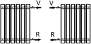
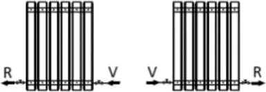
Typical connection options
Scheme for vertical and horizontal tube radiators
|
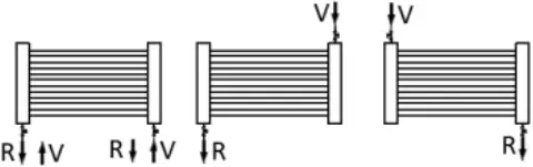 For radiators with standard connection |
 For radiators with offset or standard center connection |
 For radiators with side connection |
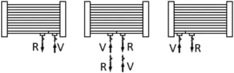
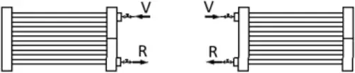
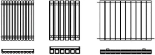
Scheme for vertical and horizontal panel and profile radiators
|
 |
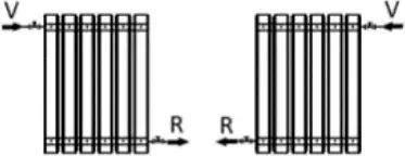 |
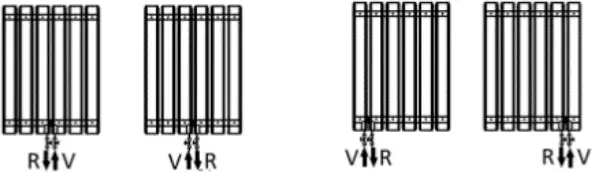 |
 |
Assembly diagram:
| (1) For radiators where brackets are positioned between the cross tubes:
Bracket: | (2) For radiators where brackets are positioned on the manifold:
Bracket: |
| (3) For radiators that are mounted with a bracket on the fixed bracket on the back: | |
Vertical | Horizontal |
 |  Bracket: |
| (4) For radiators that are mounted on the fixed pins with mounting sleeves: | |
 |  Bracket: |
5. Assembly Instructions:
- If you use the supplied masonry wall plugs, use the dimensions for the main holes (see assembly dimension table) to drill 4 holes with a depth of approx. 60 mm and a diameter of 8 mm.
- Place the wall plugs (C) in the drilled holes (only in solid walls).
- Attach the screw (D) and washer (E) to the bracket for fixing to the wall. Be careful not to overtighten the screw.
- Some radiators are fitted with a baffle. These radiators will be marked with a sticker to advise the correct way up to install the radiator. To be sure you can look inside the horizontal tubes, the baffle will be visable and must be at the bottom. If both horizontal tubes are clear the baffle is not required on that type of radiator and the direction of installation is universal.
- Hang the radiator on the bracket.
- Mount the supplied air valve (A) and the blanking plug (B) in the upper threaded openings of the radiator.
- Connect the flow and return to the selected side of the radiator using radiator valves (not included). Seal the threads watertight. We recommend use of PTFE tape or similar sealing product on all connections. Leaks as a result of incorrect sealing are not covered under the warrantee.
- How to first fill and vent the radiator:
– Open the air vent
– Slightly open the inlet valve (about 10%) while leaving the outlet valve totally closed.
– Allow the system to fill the radiator. If possible fill without use of the heating pump, it is important that the radiator is filled slowly.
– When the radiator has been filled close the air vent.
– Open both inlet and outlet valves totally and use the heating system for about 2 hours.
– Totally close both inlet and outlet.
– Open the air vent and let out all air.
– This should clear all air from the radiator. If you are still having problems, on some systems it may be necessary to fit an automatic air vent.
Care and use
– After installation, you MUST be absolutely certain that the system has been RINSE thoroughly before using it to flush out metal, flux and foreign debris. The system must also be completely vented.
– To prevent internal rust and limescale formation, a suitable inhibitor should be added to the central heating system when filling.
– Clean the radiator with a soft, damp cloth. Never use a scouring pad, scouring agent or chemical cleaning agent.
Troubleshooting
– If some pipes in your radiator are not warm, check and vent them again using the air vent. If some tubes persist in remaining cold the radiator may have been filled too quickly. Try to run it on its own to force the air out of the tube. If this does not work it may be necessary to drain and refill again slowly.
– If the radiator is generally patchy heat or takes a long time to heat it may have been fitted upside down. To check lock off the radiator on both valves, then drain water from the air valve until the top tube is empty and you are able to remove the air valve and blanking nut. Look inside the tube, it should be totally clear. If you can see the baffle it is on the wrong way up. If the radiator is fitted the correct way it may be necessary to rebalance the heating system.
Troubleshooting for electric radiators
It is normal upon first use that you may see a small amount of water discharge from the pressure valve mounted on the side at the top of the radiator. After a short time all panels on the radiator should heat up. If this does not happen, it may be necessary to top up the radiator. To do this, place the radiator on its side and undo the top side nut. Top up with normal water and replace.
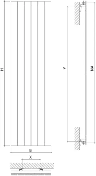
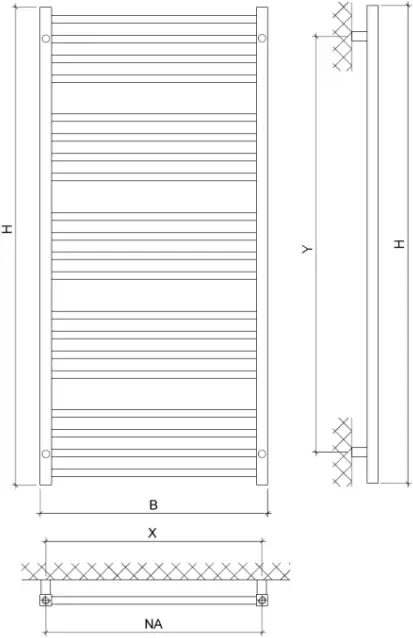
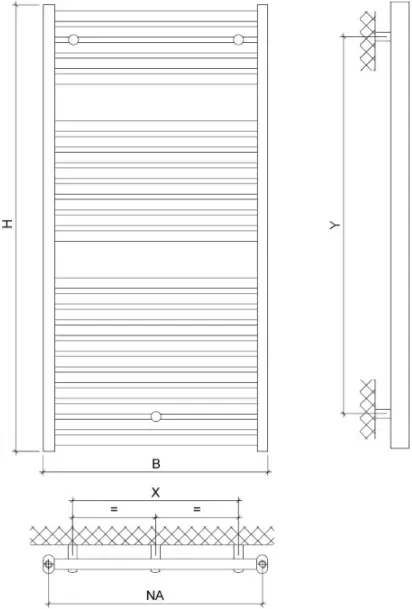
Installation dimension table for bathroom radiators | ||||||
| Model / label (See packing) | Drill hole spacing horizontal “X” | Drill hole spacing vertical “Y” | Hub spacing (NA) | Connection type | Max. Operating pressure in bar | Assembly diagram |
| PU / MT / P2O | 50 mm | H – 220 mm | 50 mm | 50 mm connection | 4 | 4 |
| PUE / MTE / P2OE | 50 mm | H – 220 mm | – | electric | 4 | 4 |
| MAG / K2D | B – 55 mm | H – 240 mm | B – 30 mm | default | 10 | 4 |
| SC / HE / K3 | B – 300 mm | H – 156 mm | 50 mm | Center connection | 10 | 1 |
| FORS / NOPR / NES | B – 50 mm | H – 178 mm | B – 50 mm | default | 10 | 4 |
| SD / PAR | 200 mm | H – 180 mm | 50 mm | Center connection | 10 | 4 |
| PAS / MAPR / P2 | B – 50 mm | H – 220 mm | B – 50 mm | default | 4 | 4 |
| PASD / MAPRD / P2D | B – 200 mm | H – 145 mm | B – 50 mm | default | 4 | 3 |
| VE / SI / PU | B – 30 mm | H – 180 mm | 50 mm | Center connection | 10 | 4 |
| FOU / NOT / FOO | 50 mm | H – 178 mm | 50 mm | 50 mm connection | 10 | 4 |
| CHA / KAL / CAD | B – 50 mm | H – 140 mm | B – 50 mm | default | 4 | 4 |
| CLC / CHG / C1 | B – 200 mm | H – 196 mm | B – 50 mm | default | 10 | 1 |
| CLC / CHG / C1 MA | B – 200 mm | H – 196 mm | 50 mm | Center connection | 10 | 1 |
| VEL / CHGB / C2 | B – 200 mm | H – 196 mm | B – 50 mm | default | 10 | 1 |
| VEL / CHGB / C2 MA | B – 200 mm | H – 196 mm | 50 mm | Center connection | 10 | 1 |
| RO / BAC / C3 | B – 120 mm | H – 172 mm | B – 50 mm | default | 10 | 1 |
| UR / VER / C4 | B – 30 mm | H – 164 mm | B – 30 mm | default | 10 | 4 |
| JAC / CEC / C5 | 100 mm | H – 124 mm | 50 mm | 50 mm connection | 5 | 1 |
| SVC / PVC / C6 | B – 32 mm | H – 120 mm | B – 32 mm | default | 5 | 4 |
| SCC / PRC / C7 | B – 60 mm | H – 300 mm | B – 60 mm | default | 5 | 4 |
| BO / MA / C8 | 72 mm | H – 168 mm | 72 mm | 72 mm connection | 10 | 4 |
| SI / CEP / HE | 50 mm | H – 124 mm | 72 mm | Center connection | 10 | 4 |
| ZE / RO | B – 160 mm | H – 170 mm | B – 30 mm | default | 10 | 1 |
| PO / FO | B – 180 mm | H – 165 mm | B – 50 mm | default | 10 | 1 |
| LU / FI / K4 | B – 76 mm | H – 180 mm | B – 80 mm | default | 10 | 4 |
| LUE / FIE / K4E | B – 76 mm | H – 180 mm | – | electric | 10 | 4 |
| POR / PRI / JOK | B – 160 mm | H – 223 mm | B – 30 mm | default | 10 | 1 |
| PORE / PRIE / JOKE | B – 160 mm | H – 223 mm | – | electric | 10 | 1 |
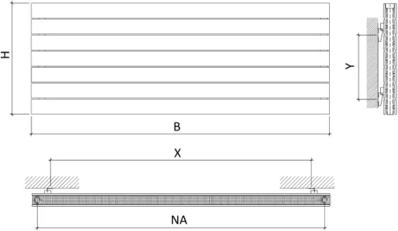
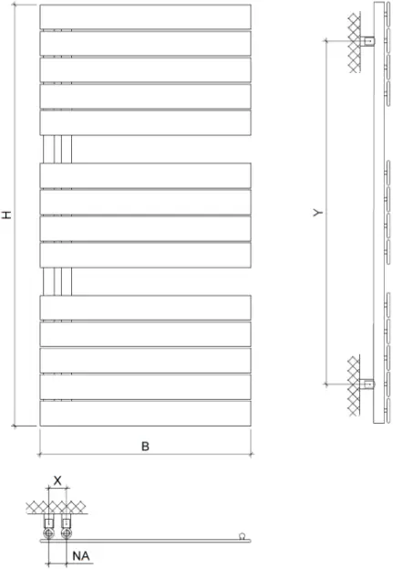
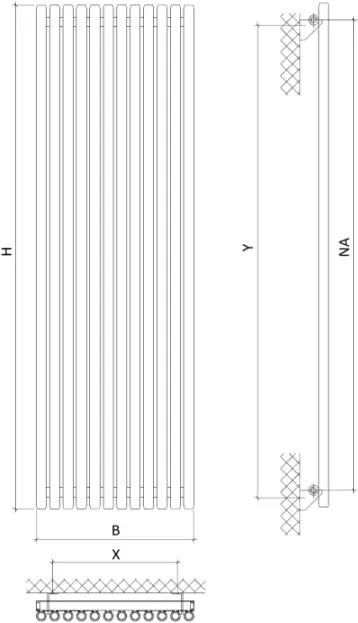
Mounting dimensions table for room heaters | ||||||
| Model / label (See packing) | Drill hole spacing horizontal “X” | Drill hole spacing vertical “Y” | Hub spacing (NA) | Connection type | Max. Operating pressure in bar | Assembly diagram |
| FOR / NO / BRI | B – 208 mm | H – 100 mm | H – 50 mm | default | 10 | 3 |
| FORD / NOD / BRID | B – 208 mm | H – 200 mm | H – 50 mm | default | 10 | 3 |
| FORH / NOH / BRIH | B – 100 mm | H – 163 mm | B – 50 mm | default | 10 | 3 |
| FORDH / NODH / BRIDH | B – 200 mm | H – 178 mm | B – 50 mm | default | 10 | 3 |
| FORM / NOM / BRIM | B – 208 mm | H – 105 mm | H – 50 mm | default | 10 | 3 |
| FORMD / NOMD / BRIMD | B – 208 mm | H – 200 mm | H – 50 mm | default | 10 | 3 |
| FORT / NOL / BRIL | B – 103 mm | H – 50 mm | H – 50 mm | default | 10 | 2 |
| SAT / AT / TA | B – 80 mm | H – 50 mm | H – 50 mm | default | 4 | 2 |
| TA4 / AT4 / AT4 | B – 167 mm | H – 50 mm | H – 50 mm | default | 4 | 2 |
| SHW / HW / OX | B – 250 mm | H – 110 mm | H – 50 mm | default | 4 | 3 |
| SHWD / HWD / OXD | B – 250 mm | H – 150 mm | H – 50 mm | default | 4 | 3 |
| SHWDS / HWDS / OXDS | B – 250 mm | H – 150 mm | H – 50 mm | default | 4 | 3 |
| SHWDHS / HWDHS / OXDHS | B – 180 mm | H – 220 mm | B – 50 mm | default | 4 | 3 |
| SHWX / HWX / OXX | B – 250 mm | H – 110 mm | H – 50 mm | default | 4 | 3 |
| SHWDX / HWDX / OXDX | B – 250 mm | H – 150 mm | H – 50 mm | default | 4 | 3 |
| SHWHX / HWHX / OXHX | B – 142 mm | H – 200 mm | B – 50 mm | default | 4 | 3 |
| SHWDHX / HWDHX / OXDHX | B – 180 mm | H – 215 mm | B – 50 mm | default | 4 | 3 |
| SHWP / HWP / OXP | B – 250 mm | H – 110 mm | H – 50 mm | default | 4 | 3 |
| SHWPDX / HWPDX / OXPDX | B – 250 mm | H – 150 mm | H – 50 mm | default | 4 | 3 |
| SHWM / HWM / OXM | B – 175 mm | H – 110 mm | H – 50 mm | default | 4 | 3 |
| SHWE / HWE / OXE | B – 250 mm | H – 110 mm | – | electric | 4 | 3 |
| SHWV / HWV / OXV | B – 250 mm | H – 110 mm | H – 50 mm | default | 4 | 3 |
| SAUR / CH / TR | B – 150 mm | H – 50 mm | 50 mm | center connection | 10 | 2 |
| SAURD / CHD / TRD | B – 150 mm | H – 50 mm | 50 mm | center connection | 10 | 2 |
| SAURE / CHE / TRE | 204 mm | H – 50 mm | 50 mm | center connection | 10 | 2 |
| SAURC / CHC / TRC | 182 mm from corner | H – 50 mm | 50 mm | center connection | 10 | 2 |
| SAURM / CHM / TRM | B – 150 mm | H – 50 mm | 50 mm | center connection | 10 | 2 |
| SAURCM / CHCM / TRCM | B – 145 mm | H – 50 mm | 50 mm | center connection | 10 | 2 |
| ES / SU / KA | B – 100 mm | H – 100 mm | H – 100 mm | default | 10 | 2 |
| ESQ / SUS / KAS | B – 100 mm | H – 100 mm | H – 100 mm | default | 10 | 2 |
| DU / VU / ER | B – 160 mm | H – 100 mm | H – 100 mm | default | 10 | 2 |
| DUV / VUQ / ERQ | B – 165 mm | H – 100 mm | H – 100 mm | default | 4 | 2 |
| SVIO / VIO / MI (H = 500) | B – 200 mm | 375 mm | 450 mm | default | 4 | 3 |
| SVIO / VIO / MI (H = 650) | B – 200 mm | 525 mm | 550 mm | default | 4 | 3 |
| DUE / VUE / ERE | B – 160 mm | H – 100 mm | – | electric | 10 | 2 |
| SHWHE / HWHE / OXHE | B – 105 mm | H – 220 mm | – | electric | 4 | 3 |
| TIHE / GAHE / KIHE | B – 300 mm | H – 220 mm | – | electric | 10 | 1 |
| FORHE / NOHE / BRIHE | B – 100 mm | H – 163 mm | – | electric | 10 | 3 |
| STP / BUP / S1P | B – 147 mm | H – 104 mm | H – 104 mm | default | 10 | 2 |
| TI22 / GA22 / KI22 | B – 85 mm | H – 50 mm | H – 50 mm | default | 10 | 2 |
| TID22 / GAD22 / KID22 | B – 85 mm | H – 50 mm | H – 50 mm | default | 10 | 2 |
| TIH22 / GAH22 / KIH22 | B – 200 mm | H – 155 mm | B – 50 mm | default | 10 | 1 |
| TIDH22 / GADH22 / KIDH22 | B – 230 mm | H – 155 mm | B – 50 mm | default | 10 | 3 |
V0422


