![]()
Visit telephone transmitter
 http://www.bellman.com/be1431/
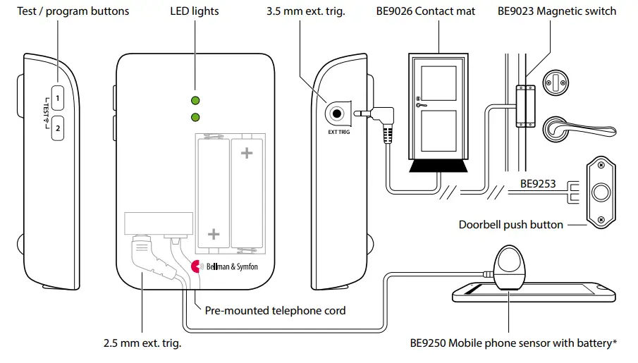
Buttons and connections
Technical specifications
In the box
- BE1431 Visit telephone transmitter
- 2×1.5 V AA alkaline batteries
- Telephone cord and adapter
- Screw and wall plug
Power and battery - Battery power: 2×1.5 V AA lithium or alkaline type batteries
- Power consumption: Active < 70 mA, Idle position < 15 μA
- Operation time:
Alkaline batteries ~ 5 years
Lithium batteries ~ 10 years
Environment - For indoor use only
- Temperature: 0° to 35° C, 32° to 95° F
- Relative humidity: 15% to 90%, non condensing
Dimensions and weight
- Height: 100 mm, 4.0″
- Width: 65 mm, 2.6″
- Depth: 27 mm, 1.1″
- Weight: 120 g, 4.2 oz. incl. batteries
Activation
- The test buttons
- A landline telephone
- A smartphone or tablet via the mobile phone sensor *
- A contact mat or magnetic switch
- A doorbell connected to the exttrig
Inputs
- RJ11 analogue telephone input
- 2.5 mm external trigger input
- 3.5 mm external trigger input
Accessories
- BE9023 Magnetic switch
- BE9026 Contact mat
- BE9250 Mobile phone sensor *
- BE9253 Ext. trig. cable, 3.5 mm
Frequency and coverage
- Frequency: 315 MHz, 433.92 MHz or 868.3 MHz, depending on region
- Coverage by region:
315 MHz: Up to 50 m (164 ft) 433 MHz: 30 – 80 m (98 – 260 ft) 868 MHz: 50 – 250 m (55 – 273 yd) - Coverage depends on the radio frequency, building’s characteristics and the combination of transmitters and receivers.
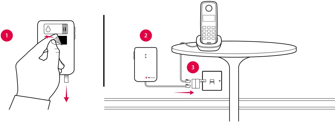
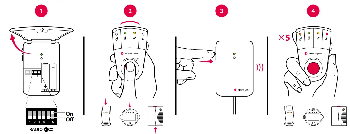
Setting up the transmitter
- Remove the battery pull tab to start the unit.
Clean the wall with the wet wipe and remove the protective film from the Velcro. - Mount the transmitter on the wall. You can also use the supplied screw and plug.
- Connect the telephone adapter as shown below.
Note: The appearance of the adapter may differ with territory.
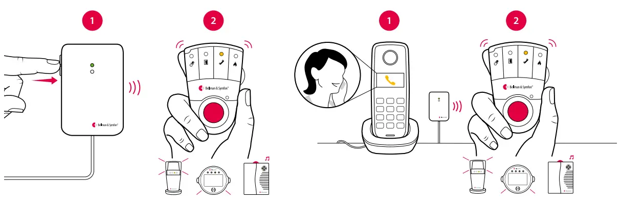
Testing the connection
Using the test button
- Press both test buttons simultaneously on the telephone transmitter. The top LED lights up in green to show that a radio signal is being transmitted.
- The yellow Visit LED on the receiver lights up to show that the signal was received. In addition, it starts to sound, flash or vibrate depending on the receiver.
Note: If you have changed the signal pattern, it will react in accordance with the table on the following spread.
Using a mobile phone
- Use for instance a mobile phone to call the landline telephone. The top LED on the transmitter lights up in green to show that an incoming call is detected.
- The yellow Visit LED on the receiver lights up to show that the radio signal was received. In addition, it starts to sound, flash or vibrate depending on the receiver.
Note: If you have changed the signal pattern, it will react in accordance with the table on the following spread.
Default signal pattern
When the telephone transmitter is activated by an incoming call or a triggered accessory, the following happens:
- The LED on the transmitter lights up to show that it’s signalling the receiver.
- The Visit LED on the receiver lights up and it starts to sound, flash or vibrate with a certain pace, called signal pattern.
The transmitter and the connected accessories determine the signal pattern. The default is as follows:
| Transmitter | |
| Source | LED |
| Landline phone | Green, top |
| Mobile phone sensor | Green, top |
| Other accessory | Green, bottom |
Receiver signal pattern
| LED | Sound | Vibration | Flash |
| Yellow light | 1xring signal, low | Medium | |
| Yellow blinks | 2xring signal, high | Medium | |
| Green light | 1xdoor chime, low | Slow |
Changing the signal pattern
The transmitter controls the signal pattern. Open the transmitter front cover and move the signal switches according to the table below to change it:
![]()
Transmitter
| Switch | Source |
| Landline phone / test button Mobile phone sensor * Other accessory | |
| Landline phone / test button Mobile phone sensor * Other accessory | |
| Landline phone / test button Mobile phone sensor * Other accessory | |
| Landline phone / test button Mobile phone sensor * Other accessory | |
| Landline phone / test button Mobile phone sensor * Other accessory | |
| Landline phone / test button Mobile phone sensor * Other accessory | |
| Landline phone / test button Mobile phone sensor * Other accessory | |
| Landline phone / test button Mobile phone sensor * Other accessory |
Receiver signal pattern
| LED | Sound | ibration | Flash | |
| Yellow light Yellow blinks Green light | 1x ring signal, low 2x ring signal, high 1x door chime, low | Medium Medium Slow | Yes Yes Yes | |
| Yellow light Yellow blinks 2x green blinks | 1x ring signal, low 2x ring signal, high 2x door chime, low | Medium Medium Slow | Yes Yes Yes | |
| Yellow light Yellow blinks 3x yellow blinks | 1x ring signal, low 2x ring signal, high 1x ring signal, high | Medium Medium Medium | Yes Yes Yes | |
| Yellow light Yellow blinks 2x orange blinks | 1x ring signal, low 2x ring signal, high Baby melody | Medium Medium Fast | Yes Yes Yes | |
| 2x yellow blinks Yellow light 3x orange blinks | 2x ring signal, low 1x ring signal, low Baby melody | Medium Medium Fast | Yes Yes Yes | |
| 2x yellow blinks Orange blinks Green blinks | 2x ring signal, low Baby melody 2x door chime, high | Medium Fast Slow | Yes Yes Yes | |
| Orange blinks 3x yellow blinks 2x green blinks | Baby melody 1x ring signal, high 2xdoor chime, low | Fast Medium Slow | Yes Yes Yes | |
| 3x yellow blinks 2x yellow blinks Green blinks | 1x ring signal, high 2x ring signal, low 2 x door chime, high | Medium Medium Slow | Yes Yes Yes |
Changing the radio key
If your Visit system is activated for no reason, there is probably a nearby system that triggers yours. In order to avoid radio interference you need to change the radio key on all units. The radio key switches are located under the transmitter cover.
Here is how you change the radio key:
- Open the transmitter front cover and move any radio key switch to the up (on position) to change the radio key. By default, all radio key switches are positioned down (off).
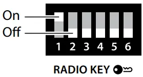
- Press and hold the test/function button on the receiver until the green and yellow Visit LEDs blink alternately. Release the button.
- Press both test buttons simultaneously on the transmitter within 30 seconds to send the new radio key.
- All Visit LEDs on the receiver blink 5 times to show that the radio key has been changed. It then returns to normal mode.
Note: All Visit units must be set to the same radio key in order to operate as a group.
Troubleshooting
| If | Try this |
| The LEDs blink in orange every minute | • Replace the batteries. Only use 1.5 V AA (LR6) lithium or alkaline batteries. |
| The transmitter LED lights up in green but the receiver doesn’t respond | Check the the transmitter batteries and the receiver batteries and connections. • Move the receiver closer to the transmitter to make sure it’s within radio range. • Check that the units are set to the same radio key, see Changing the radio key. |
| The transmitter LED doesn’t light up when the phone rings or when an accessory is triggered | • Press the test buttons on the transmitter. If the LED lights up in green, check all connections. If the LED doesn’t light up in green, replace the batteries. Only use 1.5 V AA (LR6) lithium or alkaline batteries. |
| The transmitter LED doesn’t light up when I press the test buttons | • Replace the batteries. Only use 1.5 V AA (LR6) lithium or alkaline batteries. If the LED still doesn’t light up, contact your retailer for service information. |
| The receiver is activated for no apparent reason | • There is probably another Visit system installed nearby that triggers your system. Change the radio key on all units, see Changing the radio key. |
![]() Visit_001ART011-EN
Visit_001ART011-EN
* Not available on all markets.


