
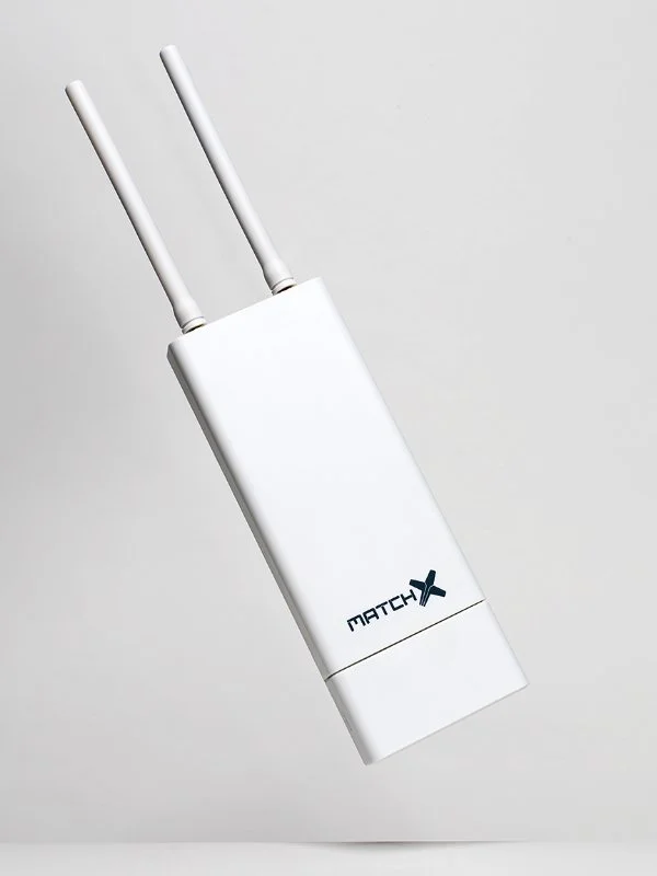
MatchX M2 Pro 16 Channels LPWAN Gateway
Introduction
Product overview
MX190x is an outdoor LPWAN gateway equipped with dual LoRa radio capable of simultaneously receive on 16 frequency channels. It is based on the newest SX1302 LoRaWAN Gateway chip which allows it to use spreading factors from SF5 to SF12. This greatly improves the throughput and decreases the data collisions in dense networks with many sensor nodes compared with previous generation of gateways based on older SX1301. Improvement on performance comes together with significant reduction of power consumption which reduces the cost of operation and increases long time reliability of the devices.
This guide covers the MX1901 and MX1902 version of MatchX M2 Pro Gateway, with the MatchX LPWAN controller version 1.0 or above. The main differences between them are listed in the Table 1.1:
| Item | MX1902 | MX1901 |
| Band Maximum Conducted Power LBT No. of Channels SF Certification
IP Rating | 902-928MHz
+27dBm Yes 16 5-10 IEC 60950 -1 FCC PART 15.247 IP66 | 863-873MHz
+27dBm Yes 16 5-12 EN 300200 EN 301489 IP66 |
Product overview
- Dual LoRa radio with 16 Rx channels
- Half-duplex LoRa communication with 2 Tx paths
- 2 LoRa antenna connectors
- Build-in GNSS receiver with GNSS engine for GPS/QZSS, GLONASS
- Build-in WiFi module with full function of 802.11b/g/n over 2.4GHz
- 100Mbase Ethernet connection with passive PoE 24V power supply
- USB-C interface for debug with Power Delivery capability for power supply
- USB-A general purpose interface
- Internal storage on SD-Card or optional flash SSD
- Secure element for key storage, secure boot and provisioning
- Accelerometer and pressure sensor for temper detection
- Auto diagnostic functions
- IP66, outdoor enclosure
- Industrial temperature range -40◦C to +85◦C
Lora
The MatchX M2 Pro fully supports LoRaWAN protocol, covering a massive vicinity of up to 20km+ in open spaces. Thanks to 16 frequencies channels and Spreading Factors as low as SF5 this gateway provides exceptionally good coverage in places with huge number of sensor devices. Based on the newest LoRa chipset SX1302 the Gateway is able to simultaneously demodulated more data packets then it was possible before reducing data collision and allowing for more dense sensor deployment in applications like smart farming, home automation or asset tracking.
WiFi
The MX1901/2 Gateways provide build in WiFi connectivity according to 2.4GHz 802.11b/g/n specification. Thanks to build in antenna no extra installation is needed. WiFi connection can be used to provide internet connection to the Gateway or to access the Web UI configuration page to manage the Gateway. If WiFi connection is not needed it can be disabled to save power.
GPS
The Gateway is equipped with Ublox MAX-7Q GNSS receiver with additional LNA to improve sensitivity and lower time to fix. The GNSS is not only used for location finding of the Gateway but also for time synchronization and precise time stamping of the received LoRa packets.
Processor Subsystem
MatchX M2 Pro gateways are based on the industry-standard i.MX6 MCIMX6G2CVM05AB processor from NXP equipped with 256MB of DDR3 RAM and 256MB of Flash memory and it is rated for extended temperature range. The low power consumption, high reliability and security options make this processor ideal for industrial application where those features are at most important. 
Interface and Connectors
Connector panel of the Gateway
The get access to the connector box of the gateway the cover needs to be removed. The cover is fixed with two screws which secure the cover from falling off during strong winds or when or during interaction with wildlife. After unscrewing the screws and pulling down the cover the connector box is easily accessible and shown on Figure 1.1. The following interfaces are available:
- Grounding screw connector – connect this with a copper wire to to ground.
- User button – used for resetting the Gateway to the factory settings.
- RGB LED – this is the status LED. Description of the possible status can be found in Table 1.2.
- USB-C connector – can be used for accessing the console terminal and to power the Gateway.
- Ethernet connector with passive 24V PoE capability for internet connection and powering the Gateway.
- USB-A 2.0 – USB host for connecting extension devices like mass storage.
Led status
The Gateway uses an RGB LED to indicate a various status and its condition. Description of the LED status can be found in Table 1.2.
| LED Color | Activity |
| Flashing Blue | Initializing |
| Steady Blue | Connected to Internet, no LoRaWAN is configured |
| Alternative Blue and Red | Device is busy, don’t unplug power |
| Steady Red | No Internet connection or LoRaWAN sever not available |
| Flashing Green | Configuring Box |
| Steady Green | Indicates that the Gateway is connected and working normally |
Console access
On default the console terminal of the Gateway can be accessed through USB-C connector. Internally CP2104 UART-USB converter is used, if the drivers for this device are not automatically installed of the PC operating system they can be downloaded from Silicon Labs website. The PC should detect the Gateway as Virtual COM port. Any terminal software capable of communicating through COM port can be used e.g. PuTTY or RealTerm. The default settings are:
- Baud rate – 115200
- Parity – none
- Stop bit – one
- Data bits – 8 bits
If the console output on USB-C port is not desirable it can be disabled in software.
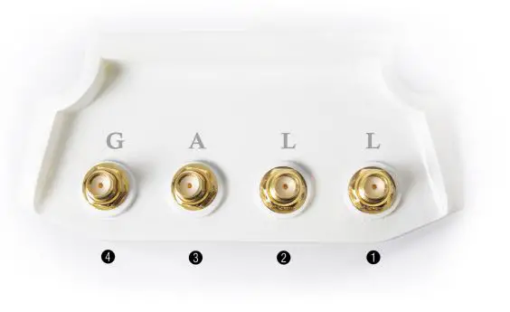
Antenna connectors
The Gateway is equipped with four high-grade SMA connectors. The connectors are waterproof and located on the top of the Gateway. The RF antennas can be attached directly to SMA connectors or can be connected with RF cable if the antenna is to be mounted in a different location or the physical size of the antenna doesn’t allow for direct connection. The location and numbering of the connectors can be seen on Figure 1.2. The functions are as follows:
- LoRa radio 1
- LoRa radio 2
- Spare connector – can be used for optional 3G/4G modem or WiFi
- GPS/GNSS
Quick Installation Guide
The MX1901/2 Gateway is preconfigured “Plug ’n Play” device, which mean installation is extremely easy. At first power up the Gateway will connect to MatchX network without any need of setup. This installation guide will guide through process of configuring the Gateway and it’s LoRa parameters. Every Gateway comes with a unique serial number and QR code placed under the cover of cable compartment. Ether of them can be used for setting up the GW on the Cloud server. The list and links to the Cloud servers can be found on MatchX website under https://www.matchx.io/
Software requirements
To use the MatchX M2 Pro Gateway no special software is required, as the Gateway is preconfigured to connect to the MatchX Cloud server. To access the Cloud Server a computer or mobile devices with a web browser such as Chrome or Firefox is sufficient. To make the installation easy it is possible to use a mobile device with QR code reader for easy registration on the chosen Cloud Server.
Hardware requirements
The hardware of the MatchX M2 Pro Gateway is design in such a way that it needs minimum number of external components to make it functional. The user has few different connection options he/she can choose from to make the installation easy and convenient. Depending on the installation option (described in next sections) the following components can be needed:
- PC computer or Mobile device
- Ethernet cable
- USB-C cable
- Access to AC power outlet
- WiFi router or Ethernet switch
- Screw driver and similar tools
Power connection
The Gateway offers two ways of supplying power:
- Passive 24V DC PoE
- USB-C
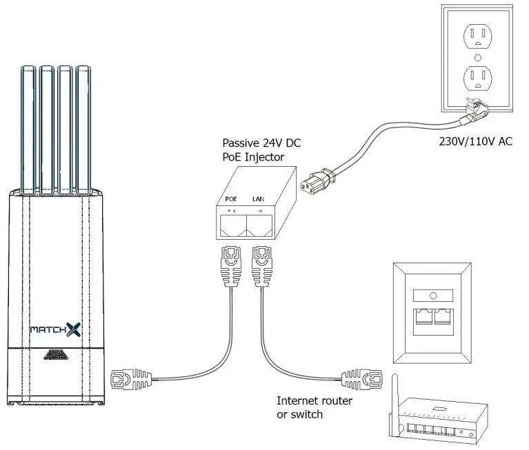
PoE power supply
On Figure 2.1 the PoE connection is illustrated. The injector has two RJ45 connectors marked as POE and LAN. It is important to pay attention to correct connection of this connectors:
- POE connector needs to be connected with Ethernet cable to the RJ45 connector of the Gateway.
- LAN connector needs to be connected with Ethernet cable to Internet router or switch.
The PoE injector needs to connected to 230/110V AC power outlet.
USB-C power supply
MX1901/2 Gateways can be powered from USB-C connector. It does implement USB PD rev 2.0 and is interoperable with USB PD rev 3.0 standard up to 22V. It is recommended to use a dedicated USB-C power supply which implements USB PD standard and has enough power capability. Powering the Gateway from USB port of PC or similar is not recommended because of limited current capabilities of those ports.
Accessing the Gateway and Internet connection
The Gateway needs internet connection in order to communicate with LoRaWAN server such as MatchX Cloud Server. There are two primary ways to provide such connection: Ethernet cable (preferred) orWiFi. For 3G/4G connection option please contact MatchX support or sales department.
Ethernet connection
Ethernet cable is a preferred way of connecting because it provides more reliable internet access and the same cable can be used to deliver 24V DC power to the Gateway. The PoE injector power supply is included together with Gateway so the user doesn’t need to spend time searching for compatible model. The connection between Gateway, PoE injector and Internet router should look like the one depicted on Figure 2.1.
After power up the Gateway should automatically get IP address assigned by the DHCP server usually running in the network. To find out the assigned IP address user can login to the router and see the list of assigned IP addresses or scan the entire local network using any available software tool like AngryIP, the gateway will appear with its serial number as hostname. After obtaining the IP address it can be used directly in the web browser like Chrome or Firefox to get access to Gateways web configuration interface if needed. If gateways autoconfiguration process was successful and internet access is available the LED should turn steady green.
WiFi connection
The WiFi interface of the Gateway works in Access Point mode by default. The SSID of the network generated by the device has a general format of: MatchX_MX190x_yyyy, where: yyyy – 4 last bytes of MAC address. The default password of the WiFi network is the serial number of the Gateway. After connecting to the network IP address will be automatically assigned to the PC or mobile device. The Web User Interface of the Gateway can be accessed by its IP address (192.168.0.1).From the Web Interface it is possible to configure the Gateway to connect to other WiFi network and use it for internet connection. In this case there is no need to connecting a Ethernet cable between LAN port of the PoE injector and Internet router.
3G/4G/LTE Option
The MatchX M2 Pro supports a optional 3G/4G/LTE modem installed inside of the gateway. MatchX offers a globally certified LTE Cat 1 module optimized for M2M and IoT applications with a worldwide LTE, UMTS/HSPA(+) and GSM/GPRS/EDGE coverage. The antenna port 3 (marked “A” on the enclosure, see Fig. 1.2) is used to connect the LTE antenna. For further information and installation guide contact MatchX or visit the WWW.MATCHX.IO website.
Mounting
This device must be professionally installed by qualified person. The Gateway is IP67 rated and can be mounted outside in vertical position. Vertical position is crucial to ensure the environmental resistance of the Gateway. Keep in mind that PoE power injector is not waterproof and has to be additionally protected if it is to be placed outside.
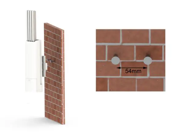
Wall Mounting
The screws and screw anchors are included in the package, users can drill two 6mm hole on the wall and apply screw anchors to them.
- Determine the place of mount, it should be an even surface.
- Mark two holes that are going to be drilled, the distance between them. should be 54mm, and they should be horizontally aligned .
- Drill two 6mm hole, apply screw anchors and screws.
- Adjust the screw spacing.
- Push the screws heads through the larger opening hole of the Gateways fixture and then pull the Gateway down so the screws get locked in position.
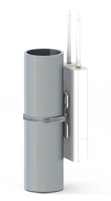
Pole mounting
The Gateway can be easily connected to a pole using a stainless steel clamp included in the box. The Gateways fixture is specially designed to fit to poles curvature. To make the mounting even more stable it is a good idea to use two clamps spaced as far apart as possible.
- Determine the place of mount, we recommend a round pole
- Position the Gateway on desired place, and fasten the stainless steel clamp.
- Tighten the screw of the clamp enough to make the mounting stable but not to much to brake the plastic fixture of the Gateway.

Surge protection and Shielded Ethernet cable
We highly recommend to use the shielded RJ45 cable to connect the Box, in order to protect the device from any possible lightning or electricity surges. Both shielded FTP and S-FTP cable from Cat5e are recommended. To protect the Gateway and Ethenet equpiment connected to it we highly recomend using lightning and surge protectors near the Gateway and near the PoE.
Product specification
Hardware Specification
| Feature | Description |
| CPU | NXP MCIMX6G2CVM05AB, 528MHz, Arm Cortex-A7 |
| Memory | 256MB DDR3 RAM/ 256MB NAND FLASH |
| Storage Memory | Optional SSD up to 32GB or industrial SD-Card |
| LoRa Radio | Two independent radio channels SX1302 chipsets, 16 frequency channels SF5-SF12, 27dBm output power 8 x 8 channels LoRa packet detectors per radio channel Supports EU868, US915, AS920, AS923, AU915, KR920, IN865 regions |
| WiFi | 2.412 GHz – 2.462 GHz, IEEE 802 Part 11b/g/n (802.11b/g/n) |
| GPS | UBlox Max 7Q GNSS receiver with additional LNA |
| Ethernet | RJ45 10/100 Mbit LAN with 24V POE |
| Console | through USB-C as virtual COM port |
| LEDs | RGB LED status indicator |
| Interface | USB-C with PD for console UART and Power USB-A 2.0 Host Reset Button |
| Internal Sensors | 3-Axis Accelerometer Pressure Sensor Temperature Sensors Voltage and Current monitoring |
| Antenna interface | 4x SMA connectors, waterproof |
| Power Supply | 24V DC passive PoE or USB-C PD rev 2.0 up to 22V |
| Power Consumption | 3.5W in average, peak 6W |
| Operating Temperature | -40◦C to 85◦C |
| Feature | Description |
| Enclosure | ASA plastic, anti-UV |
| Size (without antennas) | 101 x 226 x 73mm |
| Weight | 0.4kg |
| Installation method | Pole or Wall mounting |
WiFi specification
| Feature | Description |
| Chipset | Broadcom 43362 |
| WLAN Standards | IEEE 802 Part 11b/g/n (802.11b/g/n) |
| Antenna Port | Support Single Antenna for WiFi |
| Frequency Band | 2.412 GHz – 2.462 GHz |
| Number channels | 14 |
| Modulation | OFDM, DSSS (Direct Sequence Spread Spectrum), DBPSK, DQPSK, CCK , 16QAM, 64QAM |
| Supported rates | 1,2, 5.5,11,6,9,12,24,36,48,54 Mbps |
| Maximum receive level | -10dBm (with PER < 8%) |
| Output Power | 17 dBm +2/-2 dBm for 1, 2, 5.5, 11Mbps 14 dBm +2/-2 dBm for 6, 9, 12, 18, 24, 36, 48, 54 Mbps 12 dBm +2/-2 dBm for 11n (HT20) |
| Internal Antenna Gain | 2 dBi (Typical) |
| Internal Antenna Polarity | Linear |
| Antenna Azimuth Beamwidth | Omni-directional |
| PER <8%, Rx Sensitivity @ 1 Mbps | -94 dBm Typical |
| PER <8%, Rx Sensitivity @ 11 Mbps | -87 dBm Typical |
| PER <10%, Rx Sensitivity @ 54 Mbps | -73 dBm Typical |
| PER <10%, Rx Sensitivity @ MCS0 | -86 dBm Typical |
| PER <10%, Rx Sensitivity @ MCS7 | -70 dBm Typical |
LoRa Radio specification
| Feature | Description |
| Chipset | 2x Semtech SX1302 |
| Operating Frequency MX1901 | EU868, IN865 |
| Operating Frequency MX1902 | US915, AS923, AU915, KR920 |
| Frequencies channels per SX1302 chipset | 8 LoRa® channels multi-data rates (SF5 – SF12 / 125 kHz) + + 2 mono-data rate (LoRa® 250 / 500 kHz and FSK 50 kbps) |
| Antenna Port | 2x SMA |
| Transmit Power | 27 dBm |
| Feature | Description |
| Typical sensitivity level (EU868/US915) | down to -139 dBm at SF12 BW 125 kHz down to -127 dBm at SF7 BW 125 kHz -111 dBm at FSK 50 kbps |
GPS Antenna Performance
| Feature | Description |
| Frequency range | 1574 – 1606MHz |
| Impedance | 50ohms |
| VSWR | <1.2:1 |
| Max gain | 2.5dbi |
| Polarization | Vertical |
| Radiation Pattern | Omni-directional |
| Connector | SMA(M) |
| Length | 108mm |
| IP Rating | IP66 |
LoRa Antenna Performance
| Feature | Description |
| Frequency range | 863-873MHz |
| Or | 902-928MHz |
| Impedance | 50ohms |
| VSWR | <1.2:1 |
| Max gain | 2.5dbi |
| Polarization | Vertical |
| Radiation Pattern | Omni-directional |
| Connector | SMA(M) |
| Length | 108mm |
| IP Rating | IP66 |
Operational frequencies
MatchX Gateways are tested to work with regional frequency specifications regulated by the au- thorities responsible for given region. The user needs to pay attention to the local regulation and configure the Gateway to use proper regional settings. Table 3.6 shows example of the frequency allocation in EU868 region. Other geographic regions need to comply with their specific set of rules. LoRa Alliance is regularly publishing a summary of the regulations on their website.
| Operational Fre- quency band |
Maximum e.r.p | Channel access and occupation rules (e.g. Duty cycle or LBT + AFA) | Band num- ber from EC Decision 2013/752/EU [i.3] | Class 1 sub- class number according Commission Decision 2000/299/EU [i.7] | |
| K | 863,000 MHz to 865,000 MHz | 25 mW e.r.p. | ≤ 0,1% duty cycle or polite spectrum access | 46a | 66 |
| L | 865,000 MHz to 868,000 MHz | 25 mW e.r.p. Power density: -4,5 dBm/100 kHz | ≤ 1 % duty cycle or polite spectrum ac- cess | 47 | 67 |
| M | 868,000 MHz to 868,600 MHz | 25 mW e.r.p. | ≤ 1% duty cycle or polite spectrum ac- cess | 48 | 28 |
| N | 868,700 MHz to 869,200 MHz | 25 mW e.r.p. | ≤ 0,1% duty cycle or polite spectrum access | 50 | 29 |
| O | 869,400 MHz to 869,650 MHz | 25 mW e.r.p. | ≤ 0,1% duty cycle or polite spectrum access | 54a | 130 |
| P | 869,400 MHz to 869,650 MHz | 500 mW e.r.p. | ≤ 10 % duty cycle or polite spectrum access | 54b | 30 |
| Q | 869,700 MHz to 870,000 MHz | 5 mW e.r.p. | No requirement | 56a | 31 |
| R | 869,700 MHz to 870,000 MHz | 25 mW e.r.p. | ≤ 1% duty cycle or polite spectrum ac- cess | 56c | 69 |
Package content
MatchX M2 Pro LPWAN Gateway comes in a package containing:
• Gateway
• LPWAN and GNNS antennas
• Power Supply and power cord
• Mounting facilities (screw anchors, screws and stainless steel camp) 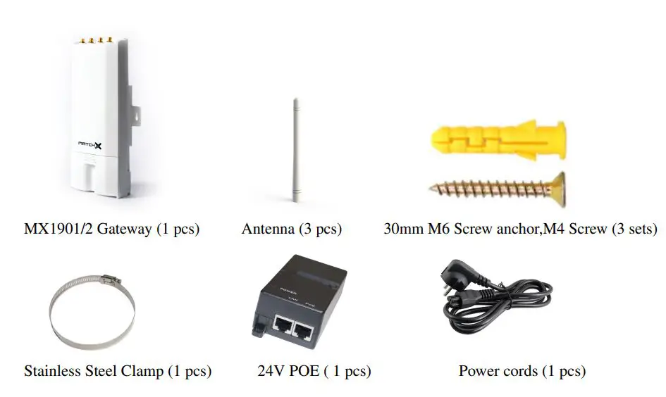
Revision History
| Revision | Description | Date |
| 1.0 | Initial Release | 15.03.2020 |
| 1.1 | Table 3.1 and 3.2 Updated the WiFi frequency Paragraph 6.1, 6.2 and 6.3 added FCC and IC notice | 18.12.2020 |
Important Notice
Legal notice
The information contained herein is believed to be reliable. MatchX makes no warranties regarding the information contained herein. MatchX assumes no responsibility or liability whatsoever for any of the information contained herein. MatchX assumes no responsibility or liability whatsoever for the use of the information contained herein. The information contained herein is provided “AS IS, WHERE IS” and with all faults, and the entire risk associated with such information is entirely with the user. All information contained herein is subject to change without notice. Customers should obtain and verify the latest relevant information before placing orders for MatchX products. The information contained herein or any use of such information does not grant, explicitly or implicitly, to any party any patent rights, licenses, or any other intellectual property rights, whether with regard to such information itself or anything described by such information. MatchX products are not warranted or authorized for use as critical components in medical, life-saving, or life-sustaining applications, or other applications where a failure would reasonably be expected to cause severe personal injury or death.
FCC regulatory conformance – applies to MX1902
This device complies with Part 15 of the FCC Rules. Operation is subject to the following two conditions:
- This device may not cause harmful interference.
- This device must accept any interference received, including interference that may cause undesired operation.
NOTE: This equipment has been tested and found to comply with the limits for a Class B digital device, pursuant to part 15 of the FCC Rules. These limits are designed to provide reasonable protec-tion against harmful interference in a residential installation. This equipment generates uses and can radiate radio frequency energy and, if not installed and used in accordance with the instructions, may cause harmful interference to radio communications. However, there is no guarantee that interference will not occur in a particular installation. If this equipment does cause harmful interference to radio or television reception, which can be determined by turning the equipment off and on, the user is encouraged to try to correct the interference by one or more of the following measures:
- Reorient or relocate the receiving antenna.
- Increase the separation between the equipment and receiver.
- Connect the equipment into an outlet on a circuit different from that to which the receiver is connected.
- Consult the dealer or an experienced radio/TV technician for help
NOTE: The manufacturer is not responsible for any radio or TV interference caused by unauthorized modifications to this equipment. Such modifications could void the user’s authority to operate the equipment.
This equipment complies with FCC radiation exposure limits set forth for an uncontrolled environment. This equipment should be installed and operated with minimum distance of 25 cm between the radiator and your body. This transmitter must not be co-located or operating in conjunction with any other antenna or transmitter.
IC regulatory conformance – applies to MX1902
This device complies with CAN ICES-3 (B)/NMB-3(B). This device complies with Industry Canada licence-exempt RSS standard(s). Operation is subject to the following two conditions:
- this device may not cause harmful interference, and
- this device must accept any interference received, including interference that may cause undesired operation.


