Hangzhou Junce Instruments Co Ltd DPH8900 Series Programmable Digital DC Power Supply
The DPH8900 Series Programmable Digital DC Power Supply is a high-quality product manufactured by Hangzhou Junce Instruments Co., Ltd. It is designed to provide reliable and accurate DC power to a wide range of electronic devices and circuits.
Product Guaranty and Declaration
The product is copyrighted by Hangzhou Junce Instruments Co., Ltd. and all rights are reserved. The JUNTEK brand is a registered trademark of the company. The product is covered by P.R.C. patents, issued and pending. Any issues or requirements related to the product or the manual can be addressed to JUNTEK through email or website.
Product Safety Requirement
The product comes with a set of safety regulations and operation instructions that must be followed to avoid any personal injury or damage to the instrument or any product connected to it. The following safety precautions must be carefully reviewed before using the instrument:
- Observe all terminal ratings.
- Use proper over-voltage protection.
- Do not operate without covers.
- Avoid inserting anything into the air outlet.
- Avoid circuit or wire exposure.
- Do not operate with suspected failures.
- Provide adequate ventilation.
- Do not operate in wet conditions.
- Do not operate in an explosive atmosphere.
- Keep instrument surfaces clean and dry.
- Prevent electrostatic impact.
Product Usage Instructions
To use the DPH8900 Series Programmable Digital DC Power Supply, please follow the steps below:
- Observe all terminal ratings and markers on the instrument and check the manual for more information about ratings before connecting the instrument.
- Ensure that no over-voltage (such as that caused by a bolt of lightning) can reach the product. Otherwise, the operator might be exposed to the danger of an electric shock.
- Do not operate the instrument with covers or panels removed.
- Do not insert anything into the air outlet to avoid damage to the instrument.
- Do not touch exposed junctions and components when the unit is powered on.
- If you suspect that any damage may occur to the instrument, have it inspected by JUNTEK authorized personnel before further operations. Any maintenance, adjustment or replacement especially to circuits or accessories must be performed by JUNTEK authorized personnel.
- Keep the instrument well ventilated and inspect the air outlet and the fan regularly.
- To avoid short circuit inside the instrument or electric shock, never operate the instrument in a humid environment.
- To avoid personal injuries or damage to the instrument, never operate the instrument in an explosive atmosphere.
- To avoid dust or moisture from affecting the performance of the instrument, keep the surfaces of the instrument clean and dry.
- Operate the instrument in an electrostatic discharge protective environment to avoid damage induced by static discharges. Always ground both the internal and external conductors of cables torelease static before making connections.
Guaranty and Declaration
Copyright
Hangzhou Junce Instruments Co., Ltd. all right reserved.
Trademark Information
JUNTEK is a registered trademark of Hangzhou Junce Instruments Co., Ltd.
Notices
JUNTEK products are covered by P.R.C. patents, issued and pending.
This document replaces all previously published documentation.
Contact Us
If you have any problem or requirement when using our products or this manual, please contact JUNTEK.
- E-mail: [email protected]
- Website: www.junteks.com
Safety Requirement
Safety Regulations and Operation
General Safety Summary.
Please review the following safety precautions carefully before putting the instrument into operation so as to avoid any personal injury or damage to the instrument and any product connected to it. To prevent potential hazards, please follow the instructions specified in this manual to use the instrument properly.
Observe All Terminal Ratings.
To avoid fire or shock hazard, observe all ratings and markers on the instrument and check your manual for more information about ratings before connecting the instrument.
Use Proper Over-voltage Protection.
Ensure that no over-voltage (such as that caused by a bolt of lightning) can reach the product. Otherwise, the operator might be exposed to the danger of an electric shock.
Do Not Operate Without Covers.
Do not operate the instrument with covers or panels removed.
Do Not Insert Anything Into the Air Outlet.
Do not insert anything into the air outlet to avoid damage to the instrument.
Avoid Circuit or Wire Exposure.
Do not touch exposed junctions and components when the unit is powered on.
Do Not Operate With Suspected Failures.
If you suspect that any damage may occur to the instrument, have it inspected by JUNTEK authorized personnel before further operations. Any maintenance, adjustment or replacement especially to circuits or accessories must be performed by JUNTEK authorized personnel.
Provide Adequate Ventilation.
Inadequate ventilation may cause an increase of temperature in the instrument, which would cause damage to the instrument. So please keep the instrument well ventilated and inspect the air outlet and the fan regularly.
Do Not Operate in Wet Conditions.
To avoid short circuit inside the instrument or electric shock, never operate the instrument in a humid environment.
Do Not Operate in an Explosive Atmosphere.
To avoid personal injuries or damage to the instrument, never operate the instrument in an explosive atmosphere.
Keep Instrument Surfaces Clean and Dry.
To avoid dust or moisture from affecting the performance of the instrument, keep the surfaces of the instrument clean and dry.
Prevent Electrostatic Impact.
Operate the instrument in an electrostatic discharge protective environment to avoid damage induced by static discharges. Always ground both the internal and external conductors of cables to release static before making connections.
Use the Battery Properly.
Do not expose the battery (if available) to high temperature or fire. Keep it out of the reach of children. Improper change of a battery (lithium battery) may cause an explosion. Use the JUNTEK specified battery only.
Handle with Caution.
Please handle with care during transportation to avoid damage to buttons, knobs, interfaces, and other parts on the panels.
Notices
- Make sure that the input power adapter is correct. This instrument adopts DC5V power adapter.
- The shell of the instrument is fragile and easy to corrode. Please don’t hit or close to chemicals to avoid corrosion.
- Working temperature: 10~50℃, storage temperature: 20~70 ℃, and keep the instrument in a dry environment.
- Do not attempt to disassemble the instrument, it will void the warranty. There are no user-serviceable parts inside the instrument. Repairs can only be made through designated repair outlets or sent back to the factory.
- Please avoid placing unsafe items such as lighted candles, cups with water, and corrosive chemicals on the surface of the instrument to avoid damage to the instrument.
- The screen is fragile, please do not touch or bump it. Please avoid children playing with the instrument. When there is dirt on the LCD surface, wipe it carefully with a soft cloth.
- When the instrument is working, please do not move the instrument violently to avoid irreparable damage to the internal circuit.
Inspection
When you get a new DPH8900 series programmable digital power supply, it is recommended to inspect the instrument according to the following steps.
Inspect the Packaging
If the packaging has been damaged, do not dispose the damaged packaging or cushioning materials until the shipment has been checked for completeness and has passed both electrical and mechanical tests.
Check the Contents
Please check the contents according to the packing lists. If the merchandise are damaged or incomplete, please contact your JUNTEK sales representative.
| Host | DPH8900 programmable digital DC power supply | 1pc |
| Attachment | Data cable | 1pc |
| Quick guide | ||
|
Optional | Programmable wireless remote controller | 1pc |
| USB to 5V cable | 1pc |
Inspect the Instrument
In case of any mechanical damage, missing parts, or failure in passing the electrical and mechanical tests, contact sales representative or our company.
Chapter 1 DPH8900 Series Products Overview
DPH8900 series power supply is a type of affordable programmable DC power supply with high performance. With superb performance specifications, pure and reliable output, and clear user interface, equipped with RS485 communication interface and TTL serial communication interface, not only providing a simple communication protocol, but also applicable to the modbus communication protocol, supporting the secondary development of users, and providing multi-purpose solutions according to your design and testing needs.
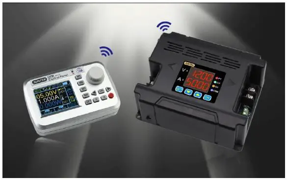
DPH8900 series power supply can be equipped with a wireless control remote controller. The wireless controller uses a 2.4-inch LCD screen, with rich display in content, it is simple to operate, with built-in lithium battery, and it can be recharged. The controller can wirelessly control the switching power supply within 10 meters, and it can control multiple power supplies at the same time.
Power supplies can be used in the following fields:
- Power field, mainly used for integrators and meters, smart meters, LED drive.
- Industrial control field.
- Medical equipment, mainly including tire guards, monitors, etc.
- Military industry, military equipments.
- Solar voltage regulation, battery charging and discharging, etc.

Specifications
| Model | DPH8909 | DPH8909-485 | DPH8920 | DPH8920-485 |
| Input voltage | 20-110V | 20-110V | 20-110V | 20-110V |
| Output voltage | 0-96V | 0-96V | 0-96V | 0-96V |
| Output current | 0-9.6A | 0-9.6A | 0-20A | 0-20A |
| Output power | 0-921.6W | 0-921.6W | 0-1920W | 0-1920W |
| Communication Interface | TTL serial communication interface | 485 communication interface | TTL serial communication interface | 485 communication interface |
| Voltage resolution | 10mV | |||
| Current resolution | 1mA | 10mA | ||
| Output ripple | <50mVpp | |||
| Efficiency | 92% | |||
| Display accuracy | 10mV、1mA | 10mV、10mA | ||
| Output tolerance | Voltage: ± 2 ‰ + 1 digit, Current: ± 5 ‰ + 2 digits | |||
| Response time | <50ms | |||
Panel Introduction
DPH8920 is taken as an example below. The operation methods of DPH8909 is the same as DPH8920. The difference is decimal places for current display, DPH8900 displays three decimal places such as: 3.000, DPH8920 displays two decimal places such as 03.00.
Indicator Introduction
PT: Temperature protection indicator. When the temperature is greater than 80 ℃, the PT light is on, indicating over-temperature protection.
CV: Constant voltage indicator. The CV indicator is on, indicating constant voltage output.
CC: Constant current indicator. The CC indicator is on, indicating constant current output.
COM: Communication indicator. When there is a command input, the COM indicator will be on, indicating normal communication.
Module Introduction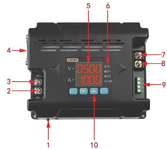
Figure1-2-1 Illustration of DPH8900 series power supply (DPH8909/ DPH8920)
Table1-2-1 DPH8900 series power supply description(DPH8909/ DPH8920)
| Item | Description | Item | Description |
| 1 | Switch | 6 | Indicator |
| 2 | Negative input terminal | 7 | Positive output terminal |
| 3 | Positive input terminal | 8 | Negative output terminal |
| 4 | LED | 9 | Communication Interface |
| 5 | Fan | 10 | Function buttons |
Display Introduction
Table 1-2-2 Display description of DPM8600 series power supply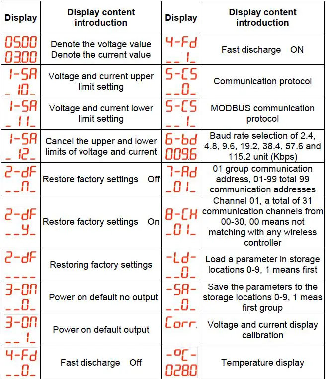
Operating Instructions
Instructions for Voltage and Current Adjustment and Shutdown Output:
- Connect the input and output correctly, and reverse connection is strictly prohibited. Ensure that the input voltage is within the required range. The input voltage must be 0.5V or more above the output voltage.
Note:- Input voltage range: 20V~110V;
- Output current range: 0~9.6A(DPH8909), 0~20A(DPH8920),
- Output voltage range: 0~96V.
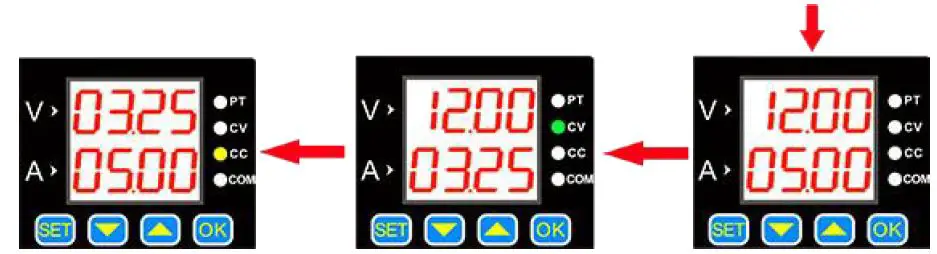
- Set the required voltage and current values. It should be noted that the V digital tube displays the voltage, and the A digital tube displays the current. After the setting, press OK to turn on the output. At this time, the CV or CC light is on, indicating that the output is turned on. The method for setting the voltage and current value is as follows (Blue indicates that the number is flashing):
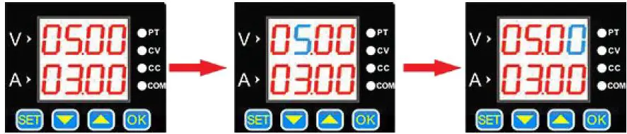
- The default setting is 5V, 3A at start-up.
- Press button 【 SET 】 shortly, a value flashes.
- Press the button 【 SET 】 continuously, the flashing position will move at different positions of voltage and current.

- When the load current reaches the set current, the output is the set current, constant current output, and the CC indicator is on.
- Press 【 OK 】 to turn the output on or off. When the load current is less than the set current, the output is constant voltage output and the CV indicator is on.
- The flashing position can be changed by【▲】and 【▼】and buttons, such as adjusting 12V, 5A. Press 【 OK 】 to exit the adjustment state.
Store and Load Function Operating Instructions
Press the up or down button on the voltage and current display interface to enter saving and loading functions, as well as the temperature display and calibrating functions.
The specific operations are as follows: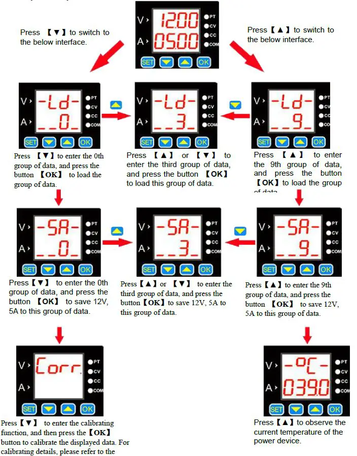
Corr Calibrating Function Introduction
- When the set voltage is greater than 20V, for example: set 25V output, but not connected to the load, the display voltage and the zero point current of 25V is calibrated (that is, the current is calibrated to zero).
- When the output is turned off, the zero display voltage and zero display current are calibrated.
- When the output is short-circuited and the current output is greater than 2A, for example, if the 3A output is set, the displayed current value of 3A is calibrated.
Temperature Display and Fan Speed Introduction
The temperature is displayed as the temperature of the current power device, which can control the fan speed and over-temperature protection. When the temperature is greater than 40 ℃, the fan starts. For every 5 ℃increase, the fan speed increases by 1 level. When the temperature reaches 60℃, the fan rotates at the maximum wind speed. When the temperature is higher than 80 ℃, the product’s over-temperature protection will automatically cut off the output.
SET Function Instructions
Press and hold 【SET】to enter the Set function setting, and then press 【SET】shortly to sequentially switch between 1-SA, 2-dF, 3-on, 4-Fd, 5-CS, 6-bd, 7-Rd, 8-CH. In each function interface, you can use the 【▲】or 【▼】 button to change the sub-options in each function setting, and press【OK】to confirm the setting
The specific operating are following: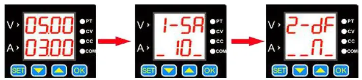
- Boot default interface
- Press and hold the 【SET】button to enter the voltage and current upper and lower limits saving interface. Use the 【▲】 or【▼】 button to change the sub-options. The storage location 10 represents the upper limit of the voltage and current settings, 11 represents the lower limit of the setting, and 12 represents the cancellation of the upper and lower limits.
Click【OK】, the setting is finished. - Press the 【SET】button shortly to enter the factory reset interface. Use the 【▲ 】 or 【▼】 button to change the sub-options. N means “No” and Y means “Yes”. Then press 【OK】, the setting is finished.

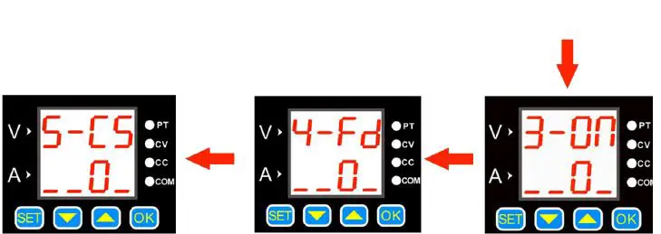
- Press the 【SET】button to enter the communication protocol selection interface. Use the 【▲】 or 【▼】 button to change the sub-options. 0 means “simple communication protocol”, 1 means “MODBUS communication protocol”, and then press 【OK】. The setting is finished.
- Press the button 【SET】 to enter the fast discharge status interface. Use the 【▲】or 【▼】button to change the sub-options. 0 means “off”, 1 means “on”, and then press the 【OK 】button.The setting is finished.
- Press the button 【SET 】to enter the power-on default output status interface. Use the 【▲ 】 or 【▼】 button to change the sub-options. 0 means “off”, 1 means “on”, then press the 【 OK 】 button. The setting is finished.

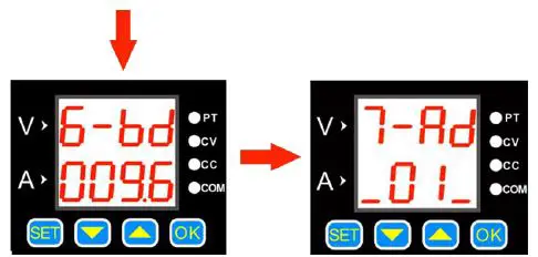
- Press the 【SET】 button shortly to enter the baud rate selection interface. There are 7 groups of baud rates in Kbps. Use the 【▲】 or 【▼ 】 button to change the baud rate, and then press the 【OK】 button. The setting is finished.
- Press the 【SET】 button shortly to enter the communication address selection interface. There are a total of 99 communication addresses from 01 to 99. Change the communication addresses by pressing the 【▲】 or 【▼】 button, and then press 【OK】.The setting is finished.
Voltage and Current Limit Function Introduction:
The upper and lower limit of the voltage and current is to set the upper and lower limit of the voltage and current adjustment. For example: set 30V, 5A on the main interface, enter the voltage and current upper limit saving location, and press OK to save them as the voltage and current upper limit. The maximum voltage adjustment range of the product is 30V and the maximum current is 5A. The same method can be used to set the lower adjustment limit.
Communication Protocol Function:
There are two kinds of communication protocols: simple communication protocol and MODBUS communication protocol, which can be selected on the product. Communication protocols are provided by our company.
Simple communication protocol is our custom communication protocol. It is easy to understand.
MODBUS communication protocol is the standard MODBUS communication protocol.
Quick Discharge Function Introduction:
After the fast discharge is turned on, when the voltage is turned from high to low, the response time is relatively short.
For example: 30V is being output, and the output is directly adjusted to 5V. When fast discharge is not turned on, it takes 5 seconds to drop from 30V to 5V, but if the fast discharge is turned on, it takes less than 1 second to drop from 30V to 5V.
Power-on Default State Settings:
The power-on default state refers to whether the output is turned on or off by default when the power is turned on. When this function is turned on, the set voltage and current value will be directly turned on after the power is turned on without any operation.
Button Lock Function
Pressing and holding the button 【OK】can lock the buttons. When the button is locked, press and hold the button 【OK】 again to cancel the button lock.
Wireless Controller Instructions
The wireless controller uses 2.4G frequency radio frequency module and wirelessly transmit signals with the power supply, which can control the power supply within a range of up to 10 meters. The wireless controller has a built-in 3.7V, 2000mA lithium battery, which can be recharged repeatedly. It can be used for more than 10 hours when fully charged. The wireless controller uses a 2.4-inch TFT LCD display, with multi-function buttons and the knob, parameters can be quickly set and adjusted, and the operation is simple and fast..
- Note: This remote control is only compatible with DPH8909-RF, DPH8920-RF, DPH8909-485RF, DPH8920-485RF models.
Product Specification
| Item | Contents |
| Wireless transmission method | RF transmission |
| Wireless transmission distance | Within 10 meters (no obstacles) |
| Communication address | 00-99 |
| Communication channel | 00-30 |
| Wireless channel | 2.4G |
| Display | 2.4 inch TFT LCD display |
| Rechargeable battery | 3.7V/2000mA |
| Dimension | 120*80*25mm |
Module description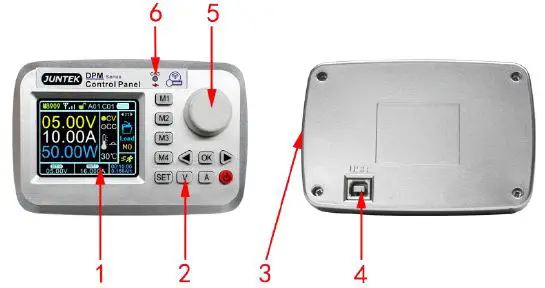 Figure 2-2-1 Wireless controller panel structure description
Figure 2-2-1 Wireless controller interface description
| Label | Description | Label | Description |
| 1 | 2.4 inch HD LCD display | 4 | USB communication interface |
| 2 | Function buttons | 5 | Knob |
| 3 | Power charging interface | 6 | Charging indicator |
Display Interface Description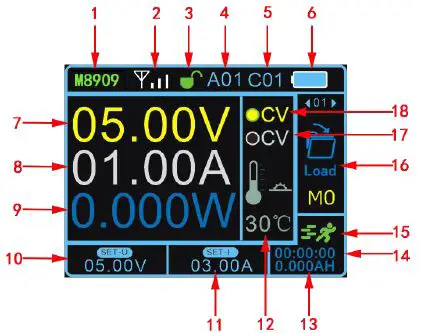
Figure 2-3-1 Display interface description
Figure 2-3-1 Display interface description
| Label | Description | Label | Description |
| 1 | Product model | 10 | Voltage setting |
| 2 | Signal address | 11 | Current setting |
| 3 | Key lock | 12 | Temperature display |
| 4 | Address 01-99 | 13 | capacity |
| 5 | Channel 01-30 | 14 | Operating time |
| 6 | Battery power | 15 | Operating status |
| 7 | Output voltage | 16 | Function bar |
| 8 | Output current | 17 | Constant current indicator |
| 9 | Output power | 18 | Constant voltage indicator |
Instructions
Voltage and current settings and output on / off
Press the button V, the cursor appears at the voltage setting, rotate the knob to change the value, press the left and right buttons to change the step value. Press button A, the cursor appears at the current setting position, rotate the knob to change the value, press the left and right buttons to change the step value. Press OK to turn the output on or off.
The voltage and current setting display interfaces are as follows: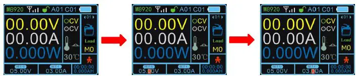
- Boot default connection status
- Voltage setting status
- Current setting status
The output status interface is as follows: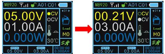
- 5V, 1A constant voltage output, when the load current is less than the set current, the output is a constant voltage output, and the CV light is on.
- When the load current reaches the set current, the output is the set current, constant current output, and the CC light is on.
Function Setting
Press the SET button on the main interface, the cursor will appear at the position of the function option box 01, press the left or right button or turn the knob to select load, save, clear, address, channel, quick response, automatic output, upper limit setting, lower limit setting, limit reset, brightness, auto power off, language, factory reset, about and other 15 function settings, press the OK button to enter function settings, press the left or right button or turn the knob to change the parameters, press the OK button to finish the setting.
An example of the function setting display interface is as follows: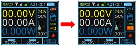
- Press the button 【SET】 and the cursor will appear at the position of the function option box.
- Press the 【OK】button to enter the function, and change the parameters through the left and right buttons or the knob.
Quick Load
The data of M1, M2, M3, M4 storage location can be loaded by pressing M1, M2, M3, M4 .
Button Lock
Press and hold the SET button to lock the button. When you press and hold the SET button again can unlock the button, after the button is locked, the button lock on the display will change to a red locked state, indicating that the button is locked.
The button lock display interface is as follows:
Upper and Lower Limit Settings
After setting the voltage and current, select the upper or lower limit to save in the function, you can set the current voltage and current value as the upper or lower limit, the upper limit is displayed as MAX, the lower limit is displayed as MIN. When the upper and lower limits are the same value, it is displayed as LOCK. Select the restriction reset function to cancel the restriction.
Upper and lower display interface: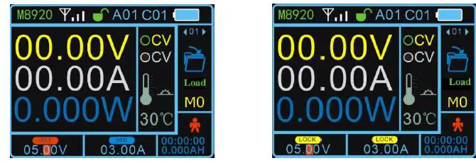
- When adjust voltage and current to reach the upper limit,【MAX】 is displayed , the lower limit is displayed as 【MIN】.
- When the upper and lower limits are the same value,it is displayed as 【LOCK】.
Function Instruction
| Number | Function | Function Instruction | |||||
| 01 | Load | Load the parameters of a certain location of 9 storage locations (M1-M9). | |||||
| 02 | Save | Save the parameters locations of M1to M9. | to | one | of | 9 | storage |
| 03 | Clear | Working hours and ampere hours are cleared. | |||||
| 04 | Address | Address (a total of 99 addresses from 01 to 99), different addresses represent different host power supply, and it can control one-to-many display. | |||||
|
05 |
Channel | Channels (a total of 30 addresses from 01 to 30), different addresses represent different host power supply, and it can control one-to-many display. Setting the host address to 00 means that it is not controlled by any wireless controller. | |||||
| 06 | Quick response | After the rapid discharge is turned on, the response time when the voltage changes from high to low is relatively short. | |||||
| 07 | Automatic output | After the automatic output is turned on, the output will be automatically turned on when the power is turned on. ON (Turn on), OFF (Turn off). | |||||
|
08 |
Upper limit setting | Set a certain value in the setting voltage and current box, enter the upper limit setting function, press the OK button, the setting is successful. After the setting is successful, when the value is adjusted to the upper limit, the setting area will display MAX, indicating that the upper limit has been reached. |
|
09 |
Lower limit setting | Set a certain value in the setting voltage and current box, enter the lower limit setting function, press the OK button, the setting is successful. After the setting is finished, when the value is adjusted to the lower limit, the setting area will display MIN, indicating that the lower limit has been reached. |
| 10 | Limit reset | Cancel the upper and lower limit settings. |
| 11 | Brightness | The brightness adjustment range is from 1% to 100%. |
|
12 | Automatic shut-down | The maximum time adjustment is 30 minutes, and the adjustment step value is 10 seconds. Setting 0 seconds means that the indicator light stays on. After turning off the screen, press the power button to turn on. |
| 13 | Language | There are two languages: Chinese and English. |
| 14 | Restore factory settings | Restore the factory setting of the wireless controller, but the factory setting of the power supply cannot be restored. |
| 15 | About | Display the product model and our company’s website, you can view product information and download materials. |
More Product Information
- For more information about this instrument, please refer to the relevant manual by logging in to the official website of JUNTEK (www.junteks.com) to download them.
- “DPH8900 Host Computer Software” provides the host computer software related to this product.
- “DPH8900 English Manual” introduces the functions of the instrument and the operation methods, possible failures and solution in using the instrument.
- “DPH8900 Communication Protocol” provides DPM8600 product communication protocol.


