![]()
Owner’s Manual
Original Instructions
Wired Controller XE73-44/E
Thank you for choosing our product.
Please read this Owner’s Manual carefully before operation and retain it for future reference.
User Notice
- Never install the wired controller in the moist circumstance or expose it directly under the sunlight.
- Never beat, throw, and frequently disassemble the wired controller and the wireless remote controller.
- Never operate the wired controller and the wireless remote controller with wet hands.
- Do not remove or install the wired controller by yourself. If there is any question, please contact our after-sales service center.
- The wired controller is a general model, applicable for several kinds of units.Some functions of the wired controller are not available for certain kinds of units, more details please refer to the owner’s manual of unit. The setting of such unavailable function will not affect unit’s operation.
- The wired controller is universal. The remote receiver is either in the indoor unit or in the wired controller. Please refer to the specific models.
- As for some indoor units connected with the wired controller, if use the remote controller whose set temperature is adjustable under auto mode, the wired controller will receive the mode signal of remote controller, rather than its set temperature under the auto mode.
- The wired controller is the universal component. When indoor unit has connected with the wired controller, display status of indoor unit is decided by the indoor unit. Valid status and invalid status are all belong to normal status.
![]() Please read the manual carefully before using and installing this product.
Please read the manual carefully before using and installing this product.
Wired Controller XE73-44/E
Symbols on LCD
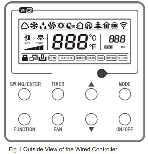
Outside View of the Wired Controller
LCD of the Wired Controller
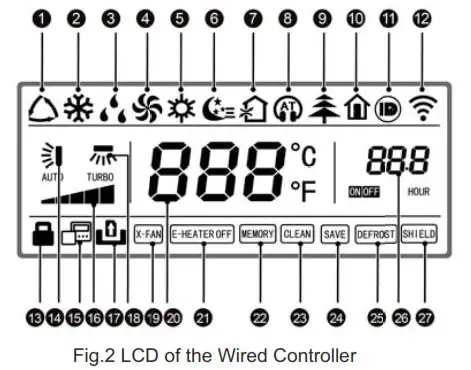
Table 1
| No. | Display | Instruction of Display |
| 1 | Auto | Automatic mode (under auto mode, the indoor unit will select its operating mode according to the variation of room temperature) |
| 2 | Cool | Cooling mode |
| 3 | Dry | Dry mode |
| 4 | Fan | Fan mode |
| 5 | Heat | Heating mode |
| 6 | Sleep | Display when sleep function is set |
| 7 | Fresh air | Display when fresh air function is set |
| 8 | Quiet | Display when quiet function is set |
| 9 | Health | Display when health function is set |
| 10 | Absent | Display when absent function is set |
| 11 | I-DEMAND | Display when I-DEMAND function is set |
| 12 | WiFi | Display when WiFi function is set |
| 13 | Child-lock | Child-lock status, display when child-lock function is set |
| 14 | Up & down swing | Display when up and down swing function is set |
| 15 | Slave wired controller | Icon of slave wired controller, it will display when slave wired controller is set (this function is unavailable for this unit) |
| 16 | Fan speed | The fan speed set currently (including auto, low, medium low, medium, medium high, high, and turbo) |
| 17 | No card | No card in gate control system |
| 18 | Left & right swing | Display when left and right swing function is set |
| 19 | X-fan | Display when X-fan function is set |
| 20 | Temperature | It will display the selling temperature |
| 21 | E-heater | On/off switch of auxiliary heating |
| 22 | Memory | Memory status (After power failure and re-energizing the unit, it will resume to ON/OFF status of unit before the power failure) |
| 23 | Clean | Filter washing reminder (this function is unavailable for this unit) |
| 24 | Save | Display when energy-saving function is set |
| 25 | Defrost | Defrosting status |
| 26 | Timer | Display when timer status is set |
| 27 | Shield | Shielding status |
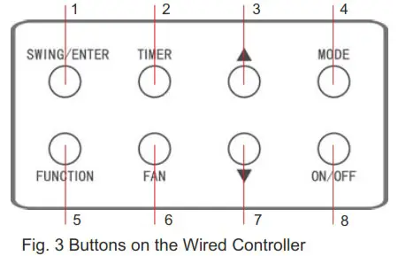
Table 2
| No. | Name | Function |
| 1 | SWING/ENTER | 1. Function selection and cancellation. 2. Setting of the up and down swing function. |
| 3 | 1. Running temperature setting of the indoor unit, range:16-30°C(61-86°F). 2. Timer setting, range:0.5-24 hr. | |
| 7 | ||
| 6 | FAN | Setting of the auto/low/medium low/medium/medium high/ high fan speed. |
| 4 | MODE | Setting of the Cooling/Heating/Fan/Dry/Auto mode of the indoor unit. |
| 5 | FUNCTION | Switchover among the functions of TurboNViFi/E-heater/X-fan etc.. |
| 2 | TIMER | Timer setting. |
| 8 | ON/OFF | Turn on/off the indoor unit. |
| 3+4 | Press them for 5s under off state of the unit to Enter/Cancel the Memory function(lf memory is set, indoor unit after power failure and then power recovery will resume the original setting state. If not, the indoor unit is defaulted to be off after power recovery. Memory off is default before delivery.). | |
| 6+7 | FAN+ | By pressing them at the same time under off state of the unit, |
| 3+7 | Upon startup of the unit without malfunction or under off state of the unit,press them at the same time for 5s to enter the lock state, in which case, any other buttons won’t respond the press. Repress them for 5s to quit this state. | |
| 4+7 | MODE+ | Under OFF state, the Celsius and Fahrenheit scales can be switched by pressing “MODE” and ” ” for 5s. |
| 2+5 | TIMER+FUNCTION | Under OFF state, it is available to go to the commissioning status by pressing “FUNCTION” and “TIMER” for five seconds, and let “00” displayed on the temperature display area by pressing “MODE”, then adjust the options which is shown on the timer area by pressing “ 1. Indoor ambient temperature is sensed by the return air temperature sensor ( 01 displayed on the timer area). 2. Indoor ambient temperature is sensed by the wired controller (02 displayed on the timer area). 3. The return air temperature sensor is selected under the cooling, dry, or fan mode; while the wired controller temperature sensor is selected under the heating or auto mode. (03 is displayed on the timer area). 4. The wired controller temperature sensor is selected under the cooling, dry, or fan mode; while the return air temperature sensor is selected under the heating mode. (04 is displayed on the timer display area). |
| 2+5 | TIMER+FUNCTION | Under OFF state, it is available to go to the commissioning status by pressing “FUNCTION” and “TIMER” for five seconds. Press “MODE” button to until “01” icon is shown at the temperature display area. The setting status will be shown at timer area. Press “ |
| 5+6 | FUNCTION + FAN | Reset the WiFi function: Under off status, press “FUNCTION” + “FAN” combination buttons on its wired controller for 5s. Once “oC” is displayed, this indicates that reset was successful. |
Operation Instructions
ON/OFF
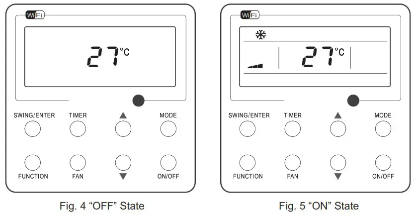
Press ON/OFF to turn on the unit and turn it off by another press.
Note: The state shown in Fig.4 indicates the “OFF” state of the unit after power on. The state shown in Fig.5 indicates the “ON” state of the unit after power on.
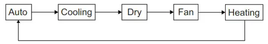
Mode Setting
Under the “ON” state of the unit, press MODE to switch the operation modes as the following sequence: Auto-Cooling-Dry-Fan-Heating.
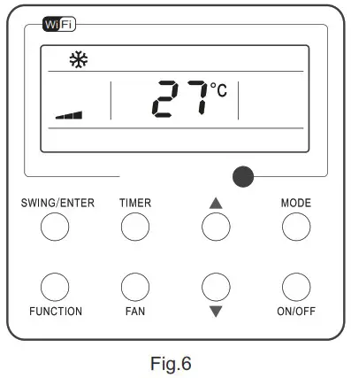
Temperature Setting
Press ![]() or
or ![]() to increase/decrease the preset temperature. If press either of them continuously, the temperature will be increased or decreased by 1°C(1°F) every 0.5s, as shown in Fig.6.
to increase/decrease the preset temperature. If press either of them continuously, the temperature will be increased or decreased by 1°C(1°F) every 0.5s, as shown in Fig.6.
In the Cooling, Dry, Fan or Heating mode, the temperature setting range is 16°C~30°C(61°F~86°F).
In the Auto mode, the setting temperature is unadjustable.
Note:
If the wired controller receives the signals of remote controller, the wired controller can analyze the set temperature adjustment function of automatic mode of the remote controller, but it needs to be used with an indoor unit with the set temperature adjustment function of automatic mode.
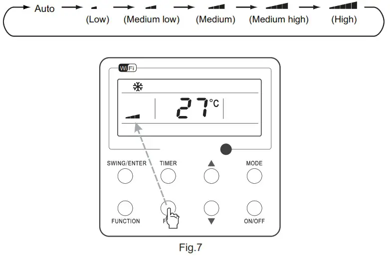
Fan Setting
Under the “ON” State of the unit, press Fan, and then fan speed of the indoor unit will change circularly as shown in Fig. 7.
 Timer Setting
 Timer Setting
Under the “ON’/”OFF’” state of the unit, press Timer to set timer off/on.
Timer on setting: press Timer, and then LCD will display “xx.x hour’, with “hour” blinking. In this case, press ![]() or
or ![]() to adjust the timing value. Then press SWING/ENTER to confirm the setting.
to adjust the timing value. Then press SWING/ENTER to confirm the setting.
Timer off setting: press Timer, if LCD won’t display xx.x hour, and then it means the timer setting is canceled.
Timer off setting under the “ON” state of the unit is shown as Fig.8.
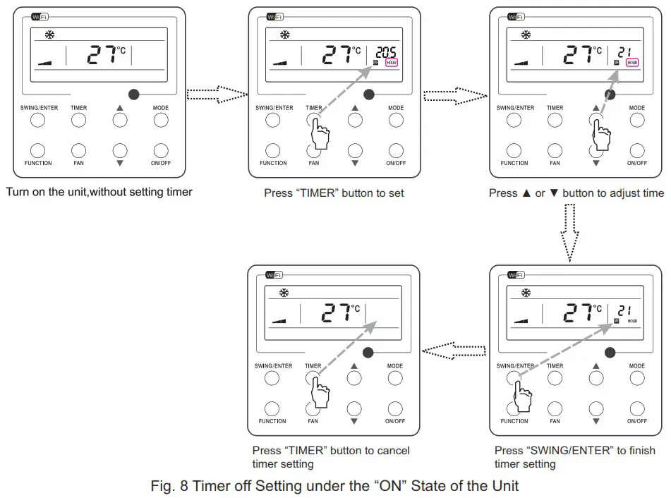
Timer range: 0.5-24hr. Every press of Aor V will make the set time increased or decreased by 0.5hr. If either of them is pressed continuously, the set time will increase/ decrease by 0.5hr every 0.5s.
Up & Down Swing Setting
There are two ways for up and down swing mode: simple swing and fixed swing. Under off status, press “SWING/ENTER’” button and “![]() ” button simultaneously for 5 seconds, then switch for simple swing, and fixed swing is done.
” button simultaneously for 5 seconds, then switch for simple swing, and fixed swing is done.
When it is set to be simple swing, under on status, press “SWING/ENTER’” button, the mode is activated, press the button again the mode is turned off.
When it is set to be fixed swing, press “SWING/ENTER’ button, the unit will circularly switch the swing mode according to the order shown below:
![]()
Left & Right Swing Setting
Swing On: Press FUNCTION under on state of the unit to activate the swing function. In this case, ![]() Will blink. After that, press SWING/ENTER to make a confirmation.
Will blink. After that, press SWING/ENTER to make a confirmation.
Swing Off: When the Swing function is on, press FUNCTION to enter the Swing setting interface, ![]() with 7 blinking. After that, press SWING/ENTER to cancel this function.
with 7 blinking. After that, press SWING/ENTER to cancel this function.
Swing setting is shown as Fig.9.
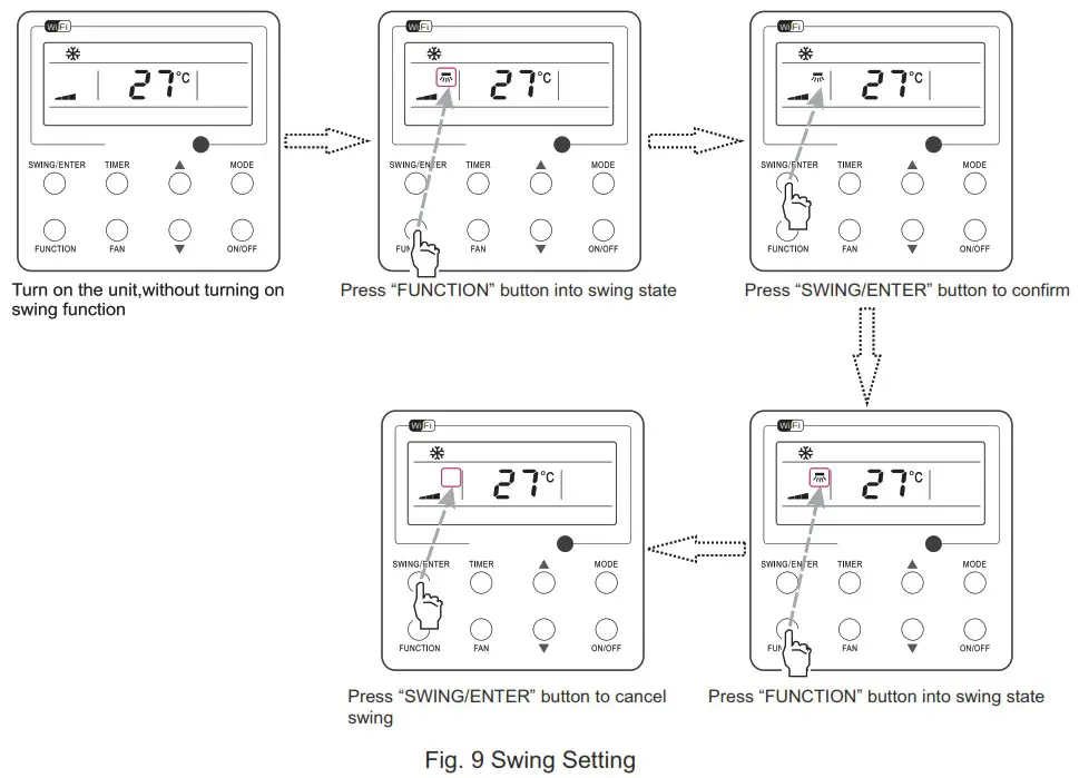
Note:
- Sleep, Turbo or X-fan setting is the same as the Swing setting.
- After the setting has been done, it has to press the key “SWING/ENTER’ to back to the setting status or quit automatically five seconds later.
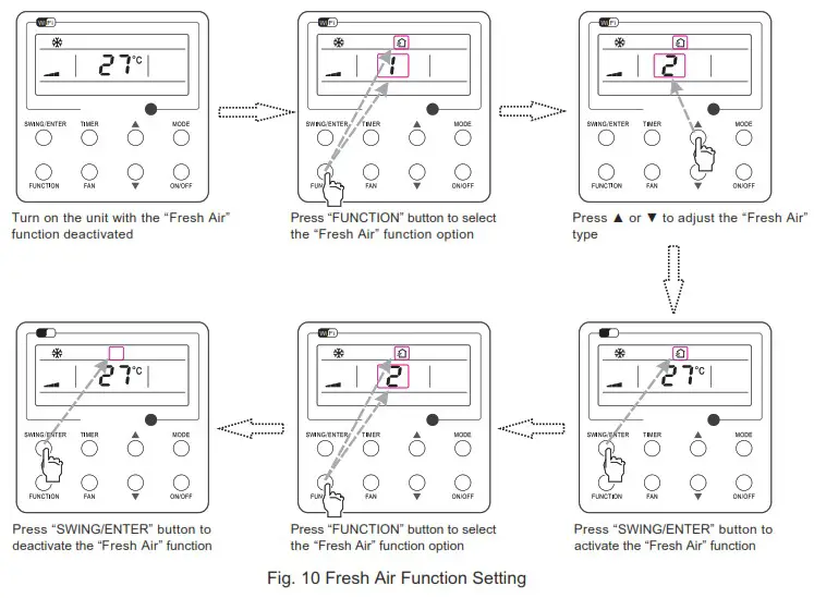
Fresh Air Valve Function Setting
Turn on fresh air valve function:
Under unit on status, press FUNCTION button on the panel to select “Fresh air valve” function option. When ![]() icon flashes, it enters fresh air valve setting mode. Previous temperature display position will display the level of fresh air valve. Press
icon flashes, it enters fresh air valve setting mode. Previous temperature display position will display the level of fresh air valve. Press ![]() or
or ![]() button to adjust the level of fresh air valve within the range from 1 to 10. Then press SWING/ENTER button to activate this function.
button to adjust the level of fresh air valve within the range from 1 to 10. Then press SWING/ENTER button to activate this function.
Turn off fresh air valve function:
If fresh air valve function has been set, press FUNCTION button on the panel to select “Fresh air valve” function option. When ![]() icon flashes, if you press SWING/ENTER button without pressing
icon flashes, if you press SWING/ENTER button without pressing ![]() or
or ![]() button, fresh air valve function will be canceled; if you press SWING/ENTER button after pressing
button, fresh air valve function will be canceled; if you press SWING/ENTER button after pressing ![]() or
or ![]() button, fresh air valve function will be activated.
button, fresh air valve function will be activated.
Note:
if you press panel button to set fresh air valve function on, ventilation (ventilation 1) function will be activated too; if you press panel button to set fresh air valve function off, ventilation function will be canceled too.
Sleep Setting
Sleep on: Press FUNCTION under on state of the unit till the unit enters the Sleep setting interface. Press SWING/ENTER to confirm the setting.
Sleep off: When the Sleep function is activated, press FUNCTION to enter the Sleep setting interface. After that, press SWING/ENTER to can this function.
Sleep setting is shown as Fig.11.
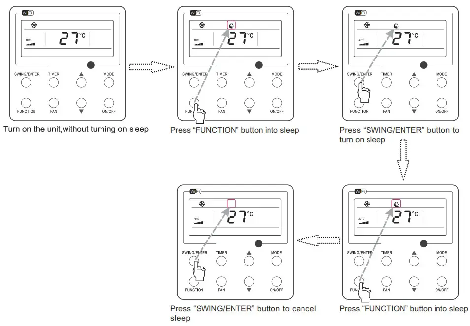
Fig.11 Sleep Setting
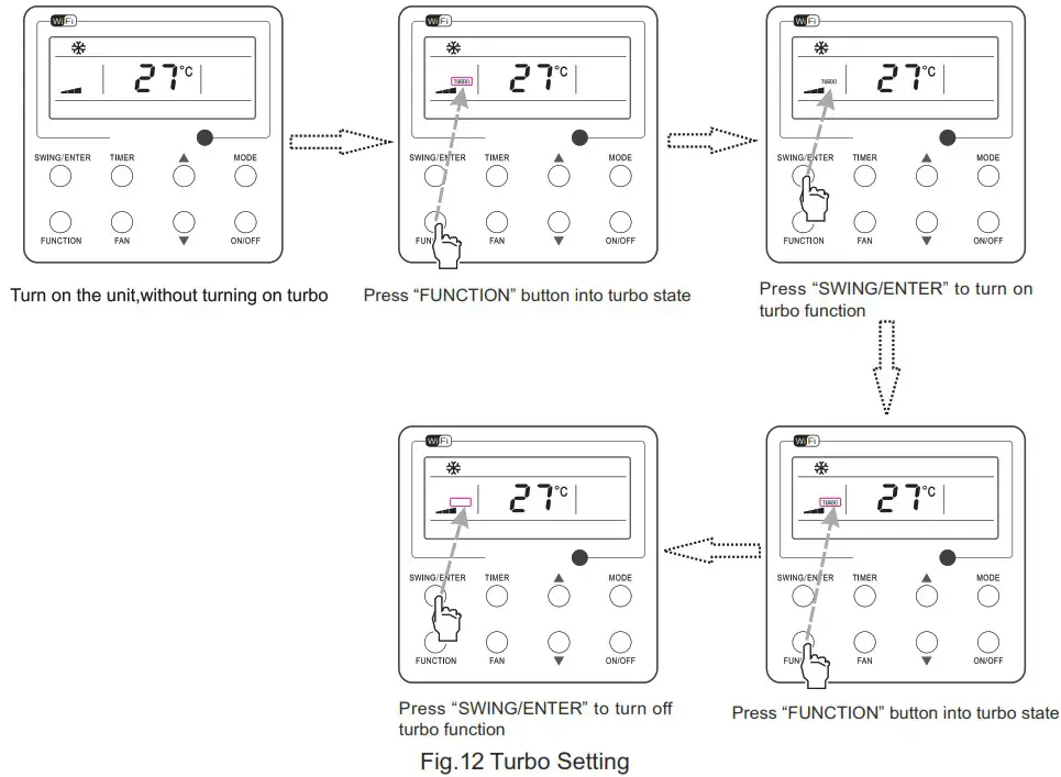
Turbo Setting
Turbo function: The unit at the high fan speed can realize quick cooling or heating so that the room temperature can quickly approach the setting value.
In the Cooling or Heating mode, press FUNCTION till the unit enters the Turbo setting interface and then press SWING/ENTER to confirm the setting.
When the Turbo function is activated, press FUNCTION to enter the Turbo setting interface and then press SWING/ENTER to cancel this function.
Turbo function setting is as shown in Fig.12.
Energy Saving Function Setting
Turn on energy saving function:
- Energy Saving Setting for Cooling
When the unit runs under the COOL or DRY mode, press FUNCTION button to select “SAVE” function option, with “SAVE” flashing, and then press or to adjust the lower limit, after that, press the SWING/ENTER button to activate this function.
 - Energy Saving Setting for Heating
When the unit runs under the HEAT mode, press FUNCTION button to select “SAVE” function option, with “SAVE” flashing, and then press or to adjust the upper limit, after that, press SWING/ENTER button to activate this function.
Note:
under energy saving setting mode, press “MODE” button to switch the energy saving setting for COOL or HEAT mode.
Cancel energy saving function:
If energy saving function has been set, press FUNCTION button on the panel to select “SAVE” function option. When Save icon flashes, if you press SWING/ENTER button without pressing ![]() or
or ![]() button, energy saving function will be canceled; if you press SWING/ENTER button after pressing
button, energy saving function will be canceled; if you press SWING/ENTER button after pressing ![]() or
or ![]() button, energy saving function will be activated.
button, energy saving function will be activated.
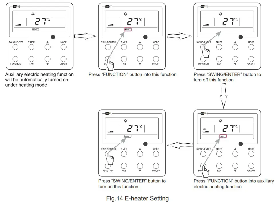
E-heater Setting
E-heater (auxiliary electric heating function): In the Heating mode, E-heater is allowed to be turned on for improvement of efficiency.
Once the wired controller or the remote controller enters the Heating mode, this function will be turned on automatically.
Press FUNCTION in the Heating mode to enter the E-heater setting interface and then press SWING/ENTER to cancel this function.
Press FUNCTION to enter the E-heater setting interface, if the E-heater function is not activated, and then press SWING/ENTER to turn it on.
The setting of this function is shown as Fig.14 below:
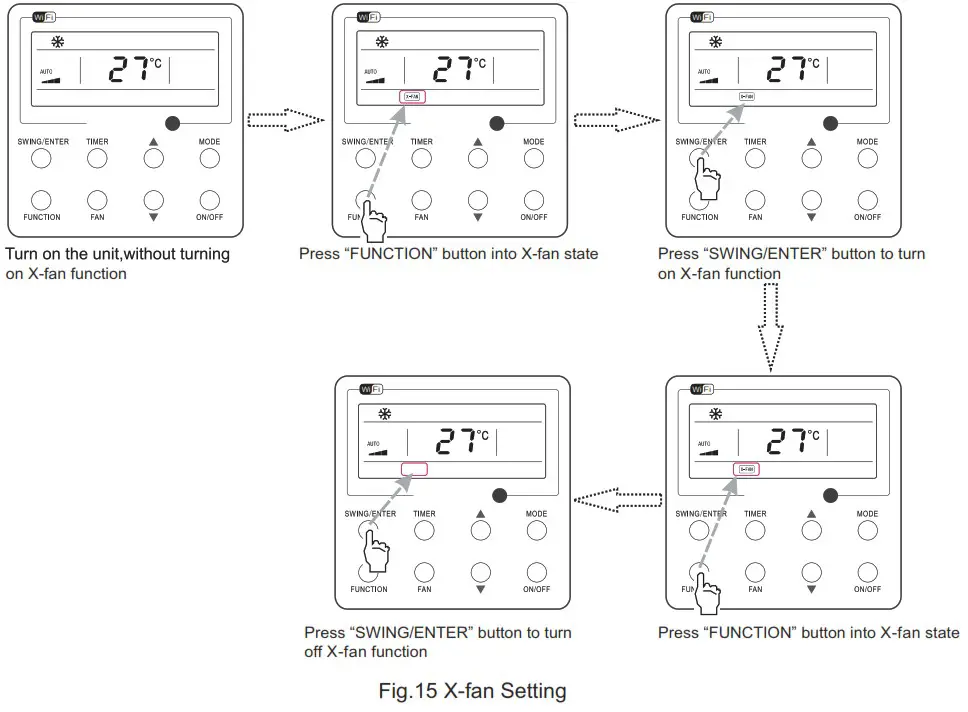
X-fan Setting
X-fan function: After the unit is turned off, the water in evaporator of indoor unit will be automatically evaporated to avoid mildew.
In the Cooling or Dry mode, press FUNCTION till the unit enters the X-fan setting interface, and then press SWING/ENTER to active this function.
When the X-fan function is activated, press FUNCTION to the X-fan setting interface and then press SWING/ENTER to cancel this function.
X-fan function setting is as shown in Fig.15
Notes:
- When the X-fan function is activated, if turning off the unit by pressing ON/OFF or by the remote controller, the indoor fan will run at the low fan speed for 2 min, with “X-FAN” displayed on the LCD. While, if the X-fan function is deactivated, the indoor fan will be turned off directly.
- X-fan function is unavailable in the Fan or Heating mode.
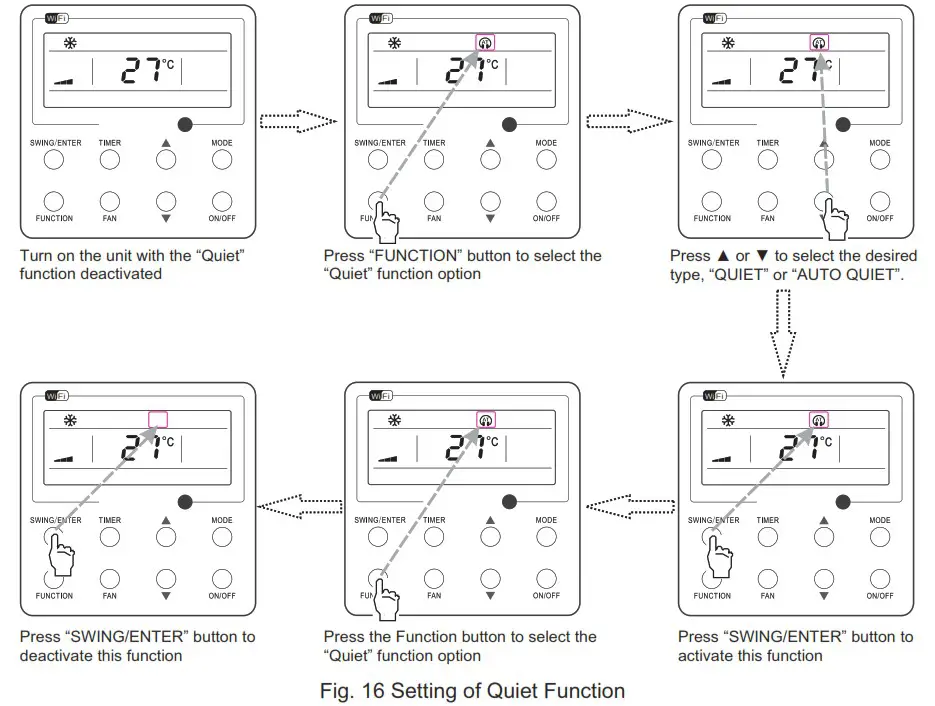
Quiet Function Setting
Turn on quiet function:
Under unit on status, press FUNCTION button on the panel to select “Quiet” function option. When “Quiet” or “Auto quiet” flashes, it enters quiet function setting mode. Press ![]() or
or ![]() button to switch between “Quiet” and “Auto quiet” function. Then press SWING/ENTER button to activate this function.
button to switch between “Quiet” and “Auto quiet” function. Then press SWING/ENTER button to activate this function.
Cancel quiet function:
If quiet function has been set, press FUNCTION button on the panel to select “Quiet” function option.
When “Quiet” or “Auto quiet” flashes, if you press SWING/ENTER button without pressing ![]() or
or ![]() button, quiet function will be canceled; if you press SWING/ENTER button after pressing
button, quiet function will be canceled; if you press SWING/ENTER button after pressing ![]() or
or ![]() button, quiet function will be activated.
button, quiet function will be activated.
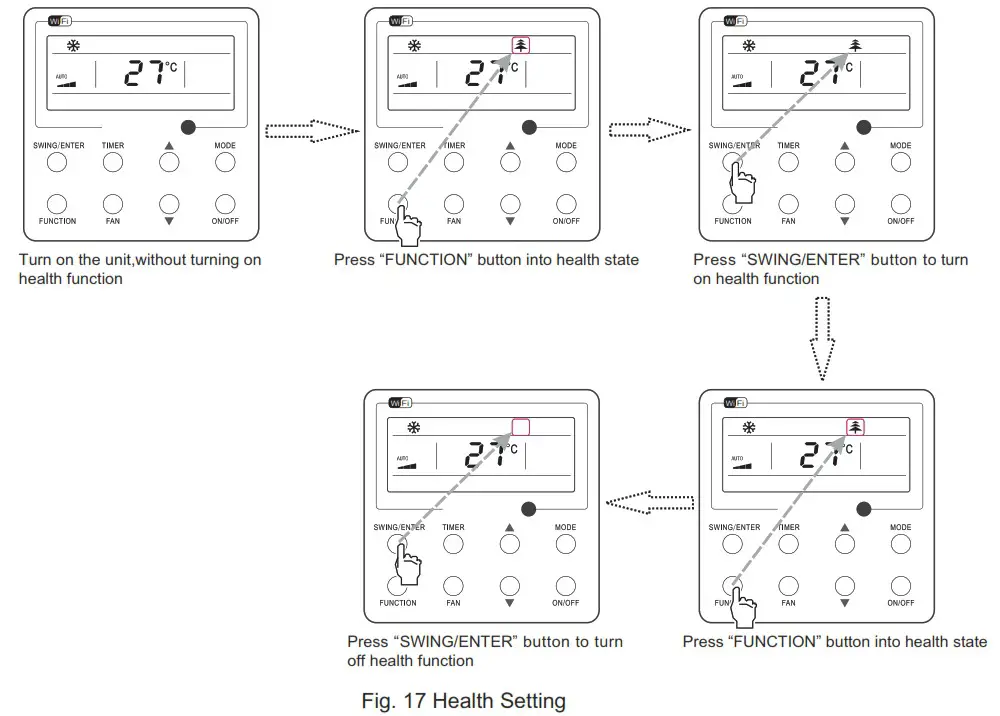
Health Setting
Health on: Press FUNCTION under on state of the unit till the unit enters the Health setting interface. Press SWING/ENTER to confirm the setting.
Health off: When the Health function is activated, press FUNCTION to enter the Health setting interface. After that, press SWING/ENTER to cancel this function.
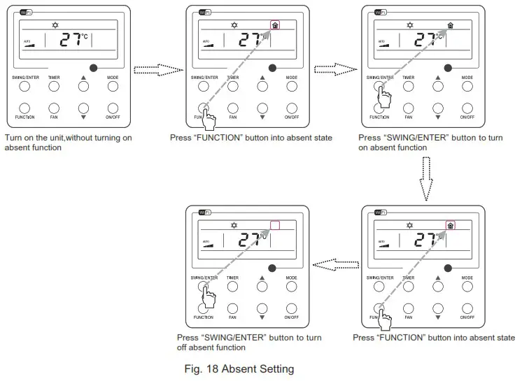
Absent Setting
Absent on: Press FUNCTION under on state of the unit till the unit enters the Absent setting interface. Press SWING/ENTER to confirm the setting.
Absent off: When the Absent function is activated, press FUNCTION to enter the Absent setting interface. After that, press SWING/ENTER to cancel this function.
Note:
- This function is only available in heating mode.
- When this function has been set, set temperature is displayed in 8°C(46°F). In this case, temperature setting and fan speed setting are shielded.
- This function will be cancelled when switching modes.
- This function and sleep function cannot be on simultaneously. If Absent function is set firstly and then sleep/quiet function is set, Absent function will be cancelled while sleep function will be valid, and vice versa.
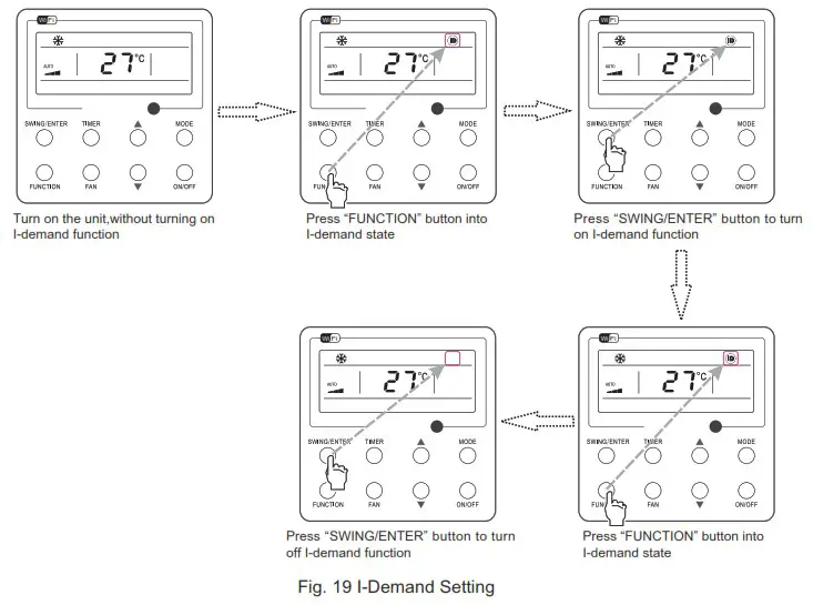
I-Demand Setting
I-Demand on: Press FUNCTION under on state of the unit till the unit enters the I-Demand setting interface. Press SWING/ENTER to confirm the setting.
I-Demand off: When the |-Demand function is activated, press FUNCTION to enter the I-Demand setting interface. After that, press SWING/ENTER to cancel this function.
Note:
- This function is only available in cooling mode.
- When this function has been set, set temperature is displayed in SE. In this case, temperature setting and fan speed setting are shielded.
- This function will be cancelled when switching modes.
- This function and sleep function cannot be on simultaneously. If I-demand function is set firstly and then sleep/quiet function is set, I-demand function will be cancelled while sleep function will be valid, and vice versa.
WiFi Function Setting
“Gree+” APP can be used to control it. Please scan the QR code to download it. APP can only set some common functions of WiFi wired controller: ON/OFF, mode, set temperature, FAN speed, etc.
When using the APP for the first time, please reset the WiFi function of wired controller (reset WiFi to ex-factory setting): Under off status, press “FUNCTION” + “FAN” combination buttons on its wired controller for 5s. Once “oC” is displayed,this indicates that reset was successful.
If there is a communication failure for WiFi, after resetting WiFi, the temperature display area of wired controller displays “JF” for 5 seconds, which indicates that the current reset is invalid.
Press FUNCTION under on state of the unit till the unit enters the WiFi setting interface, the temperature area will display the WiFi status. ![]() or
or ![]() button to turn on WiFi (“ON” is displayed) or turn off WiFi (“OFF” is displayed), and then press “SWING/ENTER”button to confirm it.
button to turn on WiFi (“ON” is displayed) or turn off WiFi (“OFF” is displayed), and then press “SWING/ENTER”button to confirm it.
Note:
WiFi can be only be reset or turned off by the buttons on the wired controller rather than the remote controller.
WiFi networking performance is related to the distance between the wired controller and the router and the obstacles between them. During the installation process, the distance between the wired controller and the router should be as close as possible, and the obstacles should be as little as possible.
If the WiFi signal is not good, use the WiFi signal enhanced router.
The specific situation depends on the actual installation.
Other Functions
- Lock
Upon startup of the unit without malfunction or under the “OFF” state of the unit, press and at the same time for 5s till the wired controller enters the Lock function. In this case, LCD displays  . After that, repress these two buttons at the same time for 5s to quit this function.
Under the Lock state, any other button press won’t get any response. - Memory
Memory switchover: Under the “OFF” state of the unit, press Mode and at the same time for 5s to switch memory states between memory on and memory off. When this function is activated, Memory will be displayed. If this function is not set, the unit will be under the “OFF” state after power failure and then power recovery.
Memory recovery: If this function has been set for the wired controller, the wired controller after power failure will resume its original running state upon power recovery. Memory contents: ON/OFF, Mode, set temperature, set fan speed and Lock function. - Selection of the Temperature Sensor
Under OFF state of the unit, press both “FUNCTION” and “TIMER” for five seconds to go the commissioning status. Under this status, adjust the display in the temperature display area to “00” through the button “MODE”, and then adjust the option of the temperature sensor in the timer display area through the button or .
1. Indoor ambient temperature is sensed at the return air inlet (01 in the timer display area).
2. Indoor ambient temperature is the sensed at the wired controller (02 in the timer display area).
3. Select the temperature sensor at the return air inlet under the cooling, dry and fan modes, while select the temperature sensor at the wired controller under the heating and auto modes. (03 in the timer display area).
4. Select the temperature sensor at the wired controller under the cooling, dry and fan modes, and select the temperature sensor at the return air inlet under the heating mode and auto modes (04 displayed in the timer display area).
After the setting, press “SWING/ENTER’” to make a confirmation and quit this setting status.
Pressing the button “ON/OFF” also can quit this commissioning status but the set data won’t be memorized.
Under the commissioning status, if there is no any operation in 20 seconds after the last button press, it will back to the previous state without memorizing the current data.
Note:
After connected with indoor unit, if the type of ambient temperature sensor has not been manually set, the wired controller will select the ambient temperature sensor according to the model of connected IDU; if it connects to cassette type IDU, duct type IDU, floor ceiling type IDU, ceiling type IDU, it will adopt (3) otherwise it will adopt (1) If the type of ambient temperature sensor is set manually, the wired controller will subject to the manual setting, and will not set according to automatic IDU model selection.
(4). Selection of the Fan Speed
Under OFF state of the unit, press both the buttons “FUNCTION” and “TIMER? for five seconds to go to the commissioning status, and then adjust the display in the temperature display area to 01 through the button “MODE” and adjust the setting of the fan speed, which comes to two options.
01: Three low fan speeds; 02: Three high fan speeds
After the setting, press “SWING/ENTER” to make a confirmation and quit this setting status.
Pressing the button “ON/OFF” also can quit this commissioning status but the set data won’t be memorized.
Under the commissioning status, if there is no any operation in 20 seconds after the last button press, it will back to the previous state without memorizing the current data.
Installation and Dismantlement
Connection of the Signal Line of the Wired Controller
- Open the cover of the electric control box of the indoor unit.
- Let the single line of the wired controller through the soleplate of wired controller.
- Connect the signal line of the wired controller to the 4-pin socket of the indoor unit .
- The communication distance between the main board and the wired controller can be up to 20 meters ( the standard distance is 8 meters)
Installation of the Wired Controller
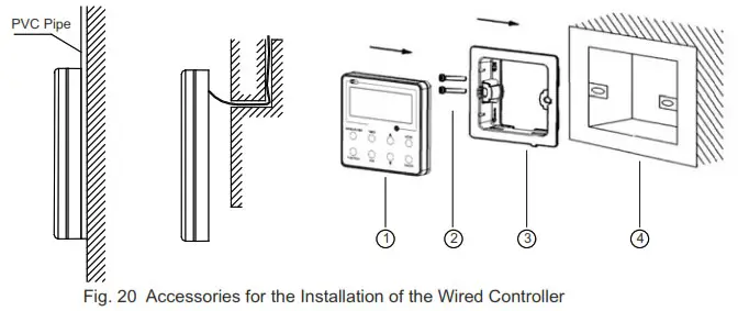
Table 3
| No. | 1 | 2 | 3 | 4 |
| Name | Front Panel of the Wired Controller | Screw M4X25 | Soleplate late of the Wired Controller | Socket box embedded in the wall |
Note:
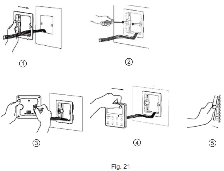
CN1 is 485 communication interface and it used Wired Controller XE73-44/E for connecting the 4-core communication wire. These two needle stands(CN2aCN3) are used for connecting the smart zone controller. There is no sequence for these two needle stands. You can connect one or two needle stand(s) basing on the requirement. Fig. 21 shows the installation steps of the wired controller, but there are some issues that need your attention.
- Prior to the installation, please firstly cut off the power supply of the wire buried in the installation hole, that is, no operation is allowed with electricity during the whole installation.
- Pull out the four-core twisted pair line from the installation holes and then let it go through the rectangular hole behind the soleplate of the wired controller.
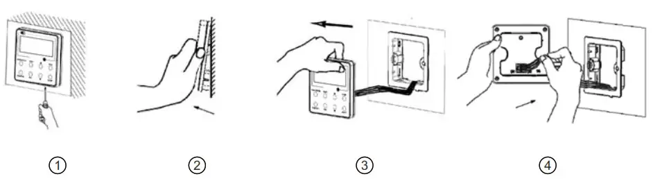
- Stick the soleplate of wired controller on the wall and then use screw M4×25 to fix soleplate and installation hole on wall together.
- Insert the four-core twisted pair line into the slot of the wired controller and then buckle the front panel and the soleplate of the wired controller together.
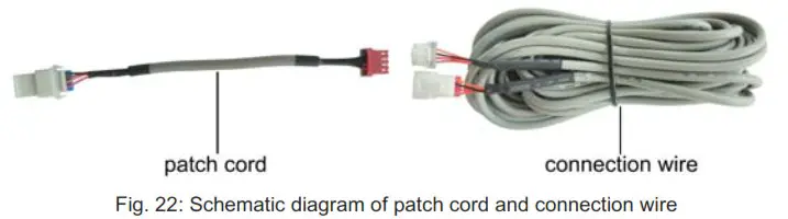
For matching with different models, the patch cord and the connection wire are provided in the packaging box of wired controller. As shown in fig. 22.
 • If the air conditioner has been installed with the patch cord (fig. 24) used for connecting the wired controller.
Only use the connection wire (fig. 23) in the packing box of wired controller. Connect the terminal (2) to the terminal (4) of patch cord which has been installed on the air conditioner; insert terminal (1) to needle stand CN1 of wired controller. If there’s protection terminal (3), pull out the protection terminal at first and then install it.
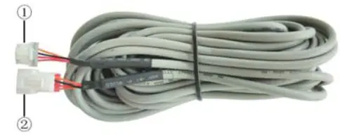 Fig. 23: Schematic diagram of connection wire: Connect terminal (1) with wired controller CN1; connect terminal (2) with the terminal (4) of patch cord
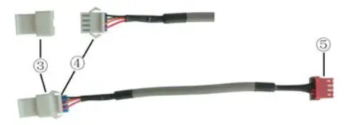
Fig. 24: Schematic diagram of patch cord: Terminal (3) is the protection terminal; connect terminal (4) to the terminal (2) of connection wire; connect
terminal (5) to the terminal of wired controller of air conditioner
- If the air conditioner hasn’t been installed with the patch cord used for connecting the wired controller.
Use the connection wire and patch cord in the packing box of wired controller. Pull out the protection terminal of patch cord at first, connect the connection wire with the patch cord according to fig. 25, and then insert the terminal (1) of connection wire into the needle stand CN1 of wired controller and insert the terminal (5) of patch cord into the terminal of wired controller of air conditioner as well. Fig. 25: Schematic diagram after the connection wire and the patch cord have been connected: connect the terminal (2) of connection wire and the
terminal (4) of patch cord
Fig. 26 shows the schematic diagram of control system connection. XE73-44/E can connect the smart zone controller (integrated control system). “n” indicates the number of communication node address (programmable wired controller XE73-44/E). The complete system is composed of the smart zone controller, wired controller XE73-44/E and communication cable. The wired controller XE73-44/E can support 16 communication node addresses at the most (ns<16).
Terminal A and terminal B of the smart zone controller are respectively connected to the corresponding communication needle stand terminal of the #1wired controller by the communication cable; the other needle stand of #1 wired controller is connected to the #2 wired controller through the telecommunication cable and so forth until connect to the #n wired controller. Except the last wired controller in the control system (only use CN2 or CN3, and the other one will not be connected), there’s no the sequence and the importance for the wired controller. The series number in the figure is only for the sake of clarity. Fig. 27 shows schematic diagram of DIP switch. There is a 2-bit DIP switch on the main board of wired controller XE73-44/E. As for the last #n wired controller in the control system, the 1-bit and the 2-bit of the DIP switch should be manually pulled to position “on” and position “off” respectively. The DIP switches of other wired controllers should be kept at the initial ex-factory status (1-bit and 2-bit are set at position “off’).
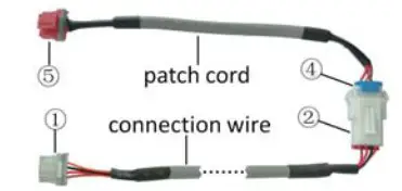 Fig. 25: Schematic diagram after the connection wire and the patch cord have been connected: connect the terminal (2) of connection wire and the
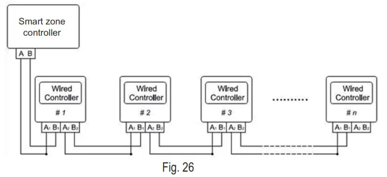
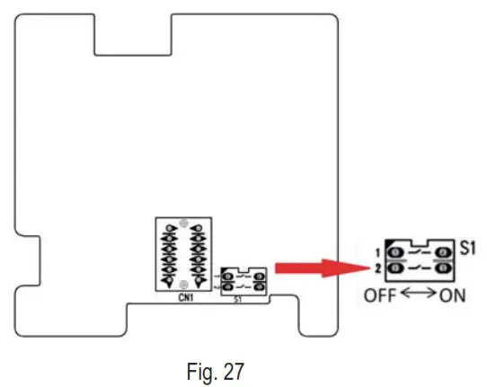 Fig. 27 shows schematic diagram of DIP switch. There is a 2-bit DIP switch on the main board of wired controller XE73-44/E. As for the last #n wired controller in the control system, the 1-bit and the 2-bit of the DIP switch should be manually pulled to position “on” and position “off” respectively. The DIP switches of other wired controllers should be kept at the initial ex-factory status (1-bit and 2-bit are set at position “off’).
![]() CAUTION!
CAUTION!
Please pay special attention to the followings during the connection to avoid the malfunction of the air conditioning unit due to electromagnetic interference.
- Separate the signal and communication lines of the wired controller from the power cord and connection lines between the indoor and outdoor unit, with a minimum interval of 20cm, otherwise the communication of the unit will probably work abnormally.
- If the air conditioning unit is installed where is vulnerable to electromagnetic interference, then the signal and communication lines of the wired controller must be the shielding twisted pair lines.
Dismantlement of the Wired Controller
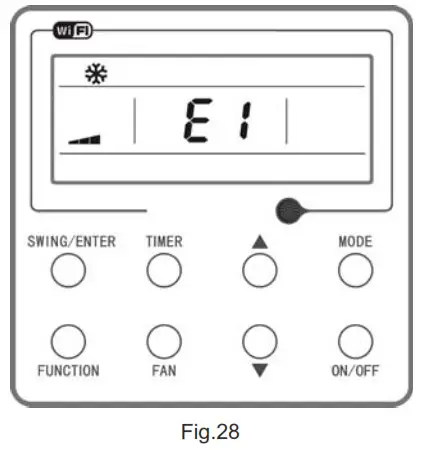
Errors Display
If there is an error occurring during the operation of the system, the error code will be displayed on the LCD, as show in Fig. 28. If multi errors occur at the same time, their codes will be displayed circularly.
Note: In event of any error, please turn off the unit and contact the professionally skilled personnel.
| Error | Error Code | Error | Error Cod |
| Return air temperature sensor open/short circuited | Fl | Drive board communication error | P6 |
| evaporator temperature sensor open/short circuited | F2 | Compressor overheating protection | H3 |
| Indoor unit liquid valve temperature sensor open/short circuited | b5 | Indoor and outdoor units unmatched | LP |
| Indoor gas valve temperature sensor open/short circuited | „ m | Communication line misconnected or expansion valve error | dn |
| IPM temperature sensor open/shon circuited | P7 | Running mode conflict | E7 |
| Outdoor ambient temperature sensor open/ short circuited | F3 | Pump-cluvei | Fo |
| Outdoor unit condenser mid-tube temperature sensor ooen/shon circuited | F4 | Defrost or oil return | |
| Discharge temperature sensor open/short circuited | F5 | Forced defrosting | Hi |
| Indoor and outdoor communication error | E6 | Compressor startup failure | Lc |
| DC bus under-voltage protection | PL | High discharge temperature protection | E4 |
| DC bus over-voltage protection | PH | Overload protection | E8 |
| Compressor phase current sensing circuit error | U1 | Whole unit over-current protection | E5 |
| Compressor demagnetization protection | HE | Over phase current protection | P5 |
| PFC protection | He | Compressor desynchronizing | f47 |
| IPM Temperature Protection | P8 | IPM Current protection | H5 |
| Over-power protection | L9 | Compressor phase loss/reversal protection | Id |
| System charge shortage or blockage Protection | FO | Frequency restricted/reduced with whole unit current protection | F8 |
| Capacitor charging error | PU | Frequency restricted/reduced with IPM current protection | En |
| High pressure protection | El | Frequency restricted/reduced with high discharge temperature | F9 |
| Low pressure protection | E3 | Frequency restricted/reduced with anti- freezing protection | FH |
| Compressor stalling | LE | Frequency restricted/reduced with overload protection | F6 |
| Over-speeding | LF | Frequency restricted/reduced with IPM temperature protection | EU |
| Drive board temperature sensor error | PF | Indoor unit full water error | E9 |
| AC contactor protection | P9 | Anti-freezing protection | E2 |
| Temperature drift protection | PE | AC input voltage abnormal | PP |
| Sensor connection protection | Pd | Whole unit current sensing circuit error | U5 |
| DC bus voltage drop error | U3 | 4-way valve reversing error | U7 |
| Outdoor fan 1 error protection | L3 | Motor stalling | I-16 |
| Outdoor fan 2 error protection | LA | PG motor zero-crossing protection | 1./8 |
| compressor inhalation temperature sensor error | do | Indoor fan tripping error | UO |
| Communication error between IDU and grid connection | Ln | IDU network address error | y3 |
| Communication error between ODU and grid connection | LM | Ip address allocation overflow | yb |
| Main error at grid connection side | y2 |