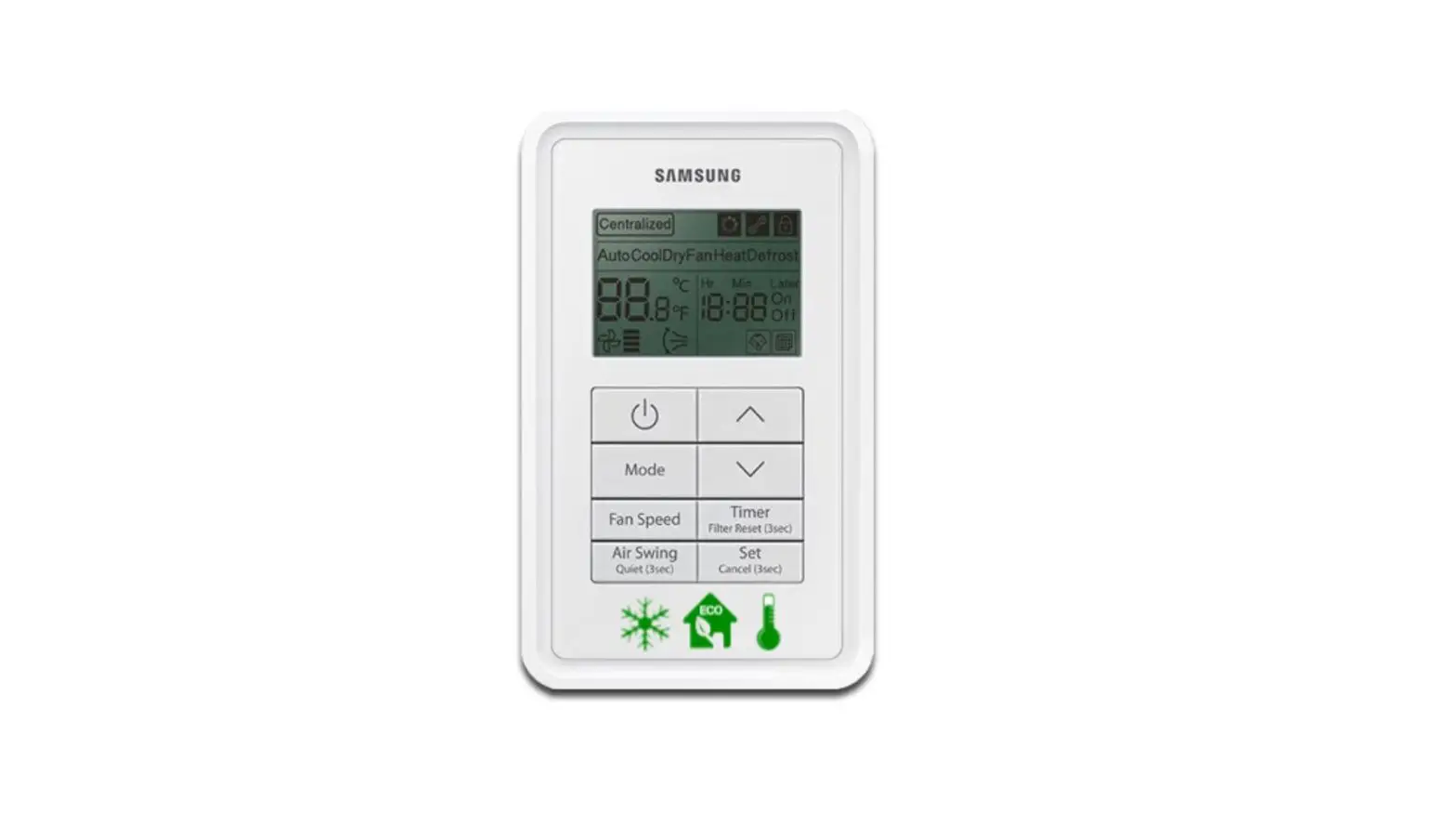
SAMSUNG MWR-VH12N ERV Wired Remote Controller Instruction Manual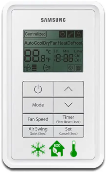
Safety Precautions
This installation manual explains how to install a ERV Wired Remote Controller connected to the indoor unit of your system air conditioner .
Please read this manual thoroughly before installing the product .
(Please refer to appropriate installation for any optional product installation .)
![]() WARNING Hazards or unsafe practices that may result in severe personal injury or death .
WARNING Hazards or unsafe practices that may result in severe personal injury or death .
![]() CAUTION Hazards or unsafe practices that may result in minor personal injury or property damage
CAUTION Hazards or unsafe practices that may result in minor personal injury or property damage
![]() WARNING
WARNING
Contact a service center for installation.
- Potential risk of malfunction, water leak, electric shock and fire .
Install the product with proper power supply.
- Potential risk of fire or product damage .
Consult the place of purchase or a contact center to disassemble or repair the product.
- Potential risk of malfunction, electric shock, or fire .
The electric work must be done by qualified person according to national wiring regulations and installation guide.
- If an unauthorized person performs the installation, any resulting defects can cause malfunctions, electrical shocks, or fire accidents .
Install the product on a hard and even place that can support its weight.
- If the place cannot support its weight, the product may fall down and it may cause product damage .
Do not move or reinstall the product on your discretion.
- Potential risk of electric shock or fire .
Check if the installation work is done correctly according to the installation manual.
- Incorrect installation may cause electric shock or fire .
When you want to dispose your Wired Remote Controller, ask the service center
Do not install the product where there’s combustible gas.
- Potential risk of fire and explosion .
Ensure no water gets into the Wired Remote Controller.
- Potential risk of electric shock or fire .
Install the air conditioner away from direct exposure to sunlight, in room temperature range of0 °C(32 °F)~39 °C(102 °F).
- Potential risk of electric shock or malfunction .
Do not handle the product with sharp objects.
- Potential risk of electric shock or product damage .
Do not install the product in areas exposed to oil or vapor.
- Potential risk of product damage or malfunction .
Do not put undue stress on the power cable.
- Potential risk of broken cable and fire .
Do not install the product in areas with frequent use of acid or alkali spray.
- Potential risk of electric shock or product malfunction
Do not connect power cable to a communication terminal.
- Potential risk of fire .
Be cautious not to interfere any other electrical devices if the product is installed in a place such as hospital.
- Potential risk of product malfunction .
Before installing ERV wired remote controller
Accessories
- ERV wired remote controller (1)

- Cable tie (2)

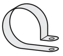
- Cable clamp (2)

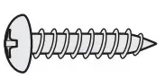
- M4X16 screw (2)

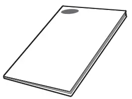
- User manual (1)

- Installation manual (1)

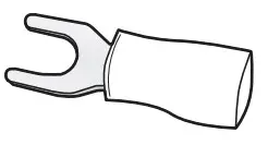
- U terminal (3)


![]() Caution
Caution
- The ERV wired remote controller should be installed by an installation expert .
- Check and confirm the power is off before installing ERV wired remote controller
- Install the ERV wired remote controller cables in accordance with the electrical wiring rules, and allow it to pass through the inner area of the wall so that other people can’t reach it
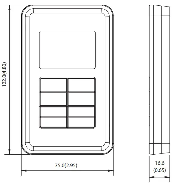
External dimension
Installing the ERV wired remote controller
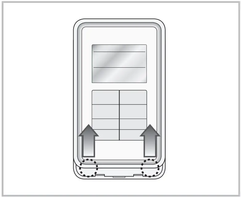
Installation procedure
- Push up the bottom part of the ERV wired remote controller’s front cover to disassemble the front cover from the mounting plate.
- ERV wired remote controller can be opened in the sliding way . (Hold the front cover and then lift it up to disassemble the front cover .)

- ERV wired remote controller can be opened in the sliding way . (Hold the front cover and then lift it up to disassemble the front cover .)
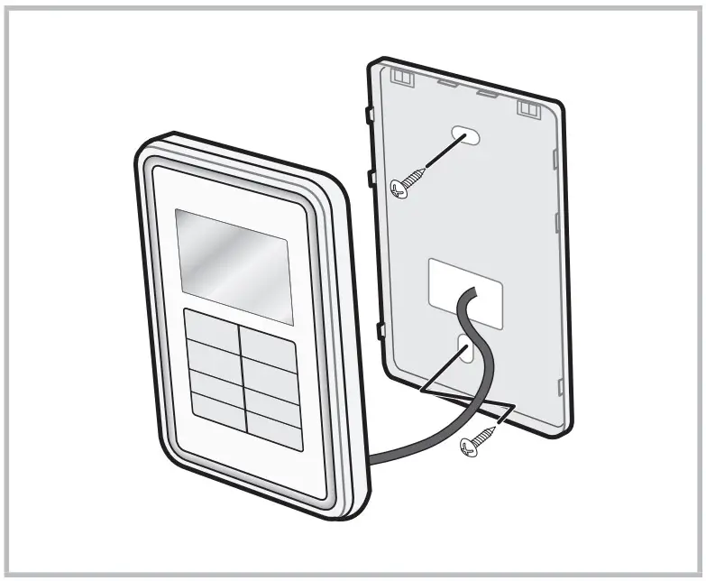
- Fix the mounting plate of the ERV wired remote controller on the wall with 2 screws.
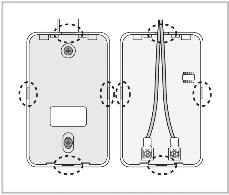
- Connect the F3, F4 of PCB terminal in ERV to F3, F4 of ERV wired remote controller terminal.

- Arrange the connected communication wires correctly depending on the installation condition.
- When the ERV wired remote controller is embedded on the wall: Make the wire go through the hole in the center of the mounting plate .
- When the ERV wired remote controller is installed on the wall: Remove the thin parts on the front and mounting plate to make the wires go through as seen in the picture
- Reassemble the ERV wired remote controller.
![]() Caution
Caution
- When installing the ERV wired remote controller by using a wire longer than 10 m, you must install the communication wire of the ERV wired remote controller and the AC power cable separately . (Electrical interference can cause your ERV wired remote controller to malfunction .)
- When installing your ERV wired remote controller on the wall, consider the size of the wire hole, and select a wire with a proper thickness .
- Wire that is connectable to ERV wired remote controller PCB .
- If you install the ERV wired remote controller by embedding it on the wall, install it according to U-terminal cable specification .
- If you install the ERV wired remote controller by using two pieces of PVC wire, remove the 30 cm of the sheath of the cable and install it only with the two pieces of wires . (Recommended specification: AWG21)
- The followings are the specs of the compressed U terminal connectable to your ERV wired remote controller PCB

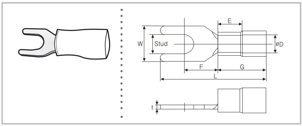
| Range of Permitted Wires | Rated Size | Stud Size | Basic Size [mm (inch)] | |||||||
| AWG | mm2(inch2) | mm2(inch2) | mm(inch) | t | øD | G | E | F | W | L |
| 22~16 | 0.25~1.65 (0.0003 ~0.0025) | 1.5(0.0023) | 3(0.1181) | 0.7(0.0275) | 3.8(0.1496) | 10.0(0.3937) | 4.5(0.1771) | 6.5(0.2559) | 6.0(0.2362) | 21.2(0.8346) |
❋ Maximum distance for connecting communication and power cable: 100 m(328 .08 ft)
- Screws on the PCB terminal must be tightened with less than 6N-cm tightening torque . If the tightening torque is greater, it may damage the screw thread
Tracking ERVs from the ERV wired remote controller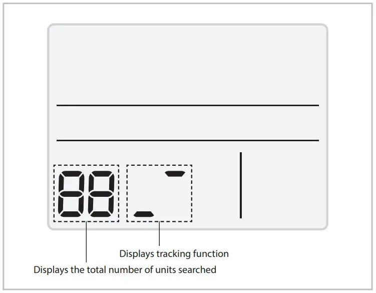
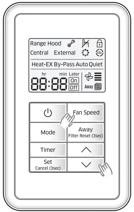
- Tracking of your ERV wired remote controller automatically starts when you turn on the power after installation.
- If you want to perform tracking again after installation, press the Fan speed and
 buttons at the same time for more than five seconds.
- The system is reset, and tracking starts again .
- During the tracking, the total number of currently searched products is displayed.
- It may take about 5 minutes at initial installation or when you re-set the master setting.
![]() Caution
Caution
- If you want to perform system reset of ERV wired remote controller, press the Fan speed and buttons at the same time for more than five seconds
When a upper controller is not connected
Individual control means that you are using one ERV wired remote controller to control one ERV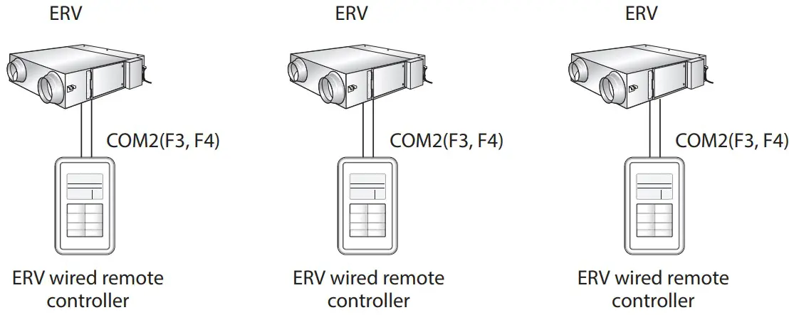
![]() Caution
Caution
- Regardless of the setting of group address (RMC address), only the ERV connected to COM2 communication wire is individually controlled
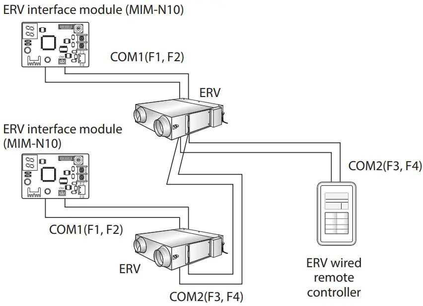
When a upper controller is connected
ERV interface module (MIM-N10)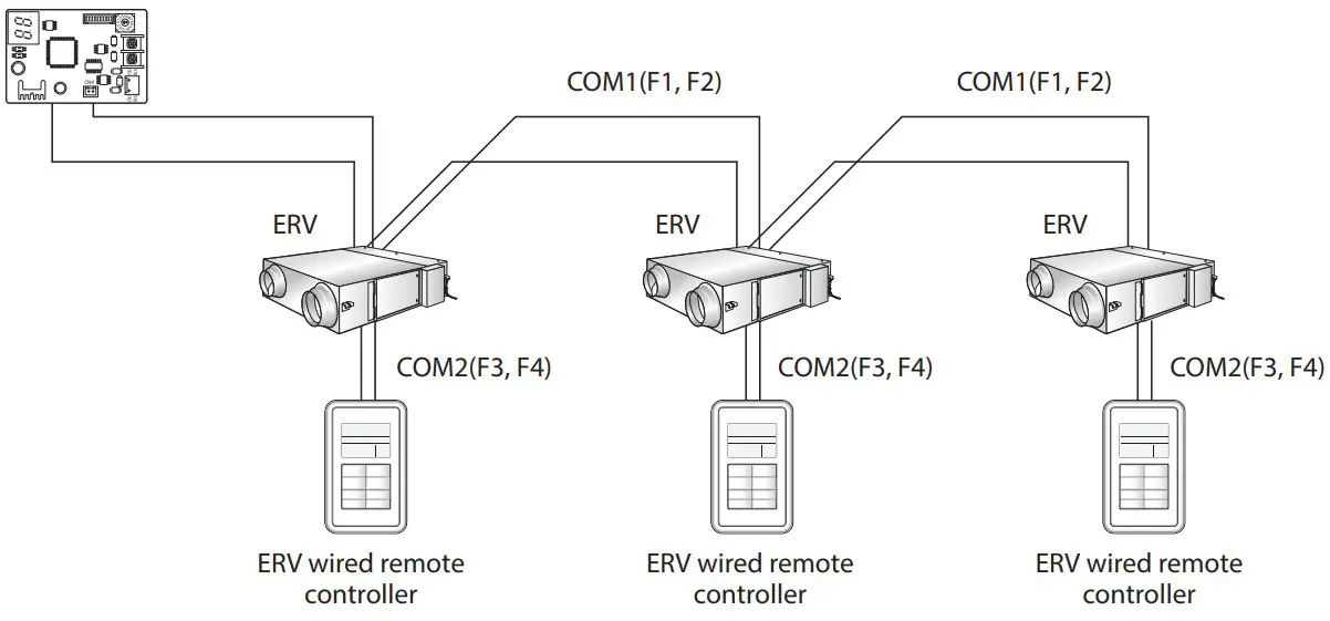
![]() Caution
Caution
- Regardless of the setting of group address (RMC address), only the ERV connected to COM2 communication wire is individually controlled
Group control with your ERV wired remote controller
Group control means that you are using one ERV wired remote controller to control two or more ERVs at the same time
- Using one ERV wired remote controller to control three ERVs.

- Using one ERV wired remote controller to control ERVs connected to other ERV repeaters in a group.

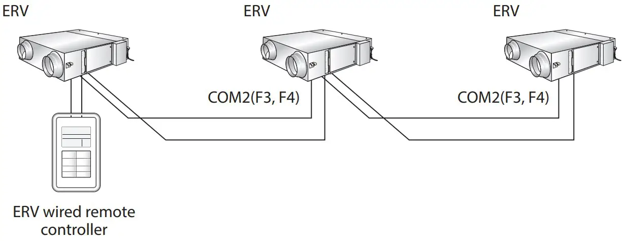
![]() Caution
Caution
- Regardless of the setting of group address (RMC address), only the ERVs connected to COM2 communication wire are controlled in a group .
- You can control the maximum of 16 ERVs as a group .
- When ERVs of other ERV repeaters are controlled in a group, address of each ERV must be set differently
Controlling 2-Remote controller
2-Remote controller means controlling one ERV or one group of ERVs with two remote controllers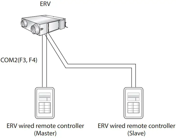
![]() Caution
Caution
- For the setting of slave ERV wired remote controller, please refer to the sections about the additional functions of the ERV wired remote controller . (Refer to the installation/service mode ) 0 : Master, 1 : Slave
Initializing the ERV wired remote controller communication
ERV wired remote controller must be initialized if installation status changes .
When the number of ERVs/indoor units or their address is changed
Press the Fan speed and ![]() buttons at the same time for more than five seconds .
buttons at the same time for more than five seconds .
- Your ERV wired remote controller is initialized, and the device searches for the indoor units/ERVs connected to your ERV wired remote controller again

Errors displayed on the ERV wired remote controller
Error codes for the ERV wired remote controller or the products connected to the ERV wired remote controller are displayed on the LCD display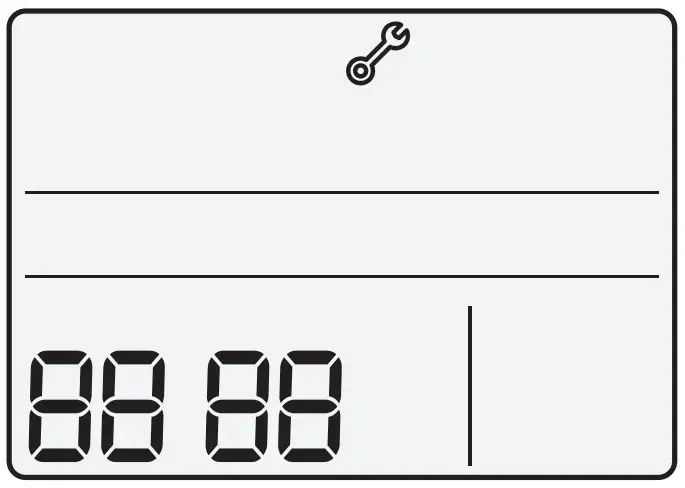
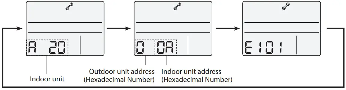
When an error occurs in indoor/outdoor units (Product group display: A20)
- The product address for the error is displayed, followed by the error code . Example : Error 101 occurs for Indoor Unit 10 (decimal number)

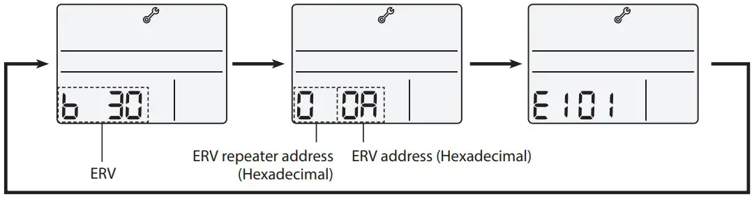
When an error occurs in ERVs or ERV repeaters (Product Group Display: b30)
- The product address for the error is displayed, followed by the error code . Example : Error 101 occurs for ERV 10 (decimal number)

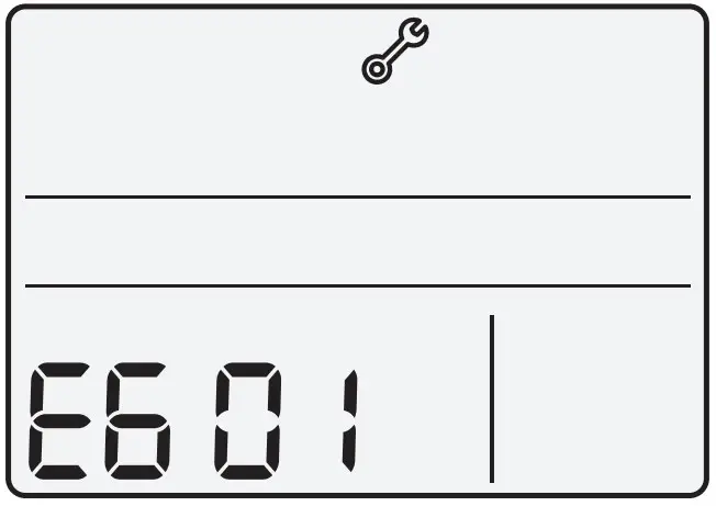
When an error occurs in ERV wired remote controller
- Only an error code is displayed . (No address is displayed .) Example : Error 601 has occurred at your ERV wired remote controller

Error codes of ERV wired remote controller
| Indication | Description |
 | • Tracking between ERV wired remote controller and ERV is not completed within 3 minutes. |
 | • Indoor unit is not installed when external interlock function is executed. |
 | • The maximum number of installation is exceeded. (Maximum:16)• Reset is required after checking the number of installed devices. |
 | • Error on installation of slave ERV wired remote controller (When more than 2 slave ERV wired remote controllers are installed.) |
 | • Communication error between master ERV wired remote controller and slave ERV wired remote controller |
 | • Communication error between ERV wired remote controller and ERV/indoor units (After completing the tracking of ERV wired remote controller, communication does not work for 3 minutes.) |
 | • EEPROM error |
![]() Caution
Caution
- Refer to the installation manual of each device for error codes of ERVs
Using installation/service mode of ERV wired remote controller
Additional functions of ERV wired remote controller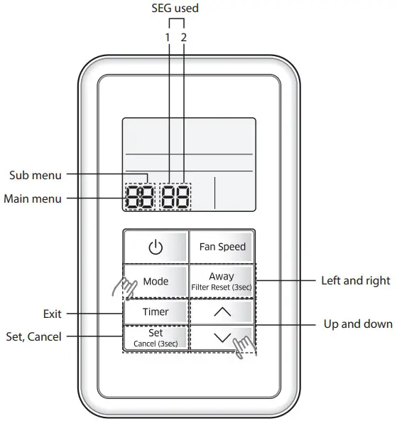
- If you want to use the various additional functions for the ERV wired remote controller, press the Mode and buttons at the same time for more than three seconds.
- You will enter the additional function settings, and the main menu is displayed .
- Refer to the list of additional functions for the ERV wired remote controller on the next page, and select the desired menu.
- Using the
 buttons, select a main menu number and press the Away button to enter the sub-menu setting screen .
 - Using the buttons, select a sub-menu number and press the Away button to enter data setting screen .
- When you enter the setting stage, the current setting is displayed .
- Refer to the chart for data settings .
- Using the buttons, select the settings and press the Away button to move to the next setting .
- Press the Set button to save the settings and exit to the sub-menu setting screen
- Press the Timer button to exit to normal mode
- Using the
 Note
Note
- While setting the data, press the Mode or Away button to move the digit of SEG .
- If you press the Timer button while your are setting data, you can exit to the sub menu setting stage without saving your changes
Installation/service setting mode
Note
- If communication initialization is needed after the setting, the system resets automatically and communication is initialized
| Main menu | Sub menu | Function | Factory setting | Page number | Range | Remarks | |
| 0 | 1 | Reset | Reset to default value of ERV wired remotecontroller option setting | 0 | 1 | 0-Disuse, 1-Reset | |
| 2 | Reset to factory setting of ERV wired remote controller | 0 | 1 | 0-Disuse, 1-Reset | |||
| 3 | Power Master Reset 3)* | 0 | 1 | 0-Disuse, 1-Reset | |||
| 4 | Addressing Reset | 0 | 1 | 0-Disuse, 1-Reset | |||
| 1 | 1 | Information on ERV wired remote controller | Checking the number of connected indoor units | 0 | 1 | 0~16 EA | |
| 2 | Checking the number of connected ERVs | 0 | 1 | 0~16 EA | |||
| 3 | Checking the Micom code of ERV wired remote controller | none | 3 | Micom code | |||
| 4 | Checking the program version informationof ERV wired remotecontroller | none | 3 | Modified date | |||
| 2 | 1 | Setting address/ option 2)* | Target | ERV View Master | 3 | Address of registerd devices / hexadecimal 5)* | |
| 2 | Setting/checking main address | Main address of target | 1 | Main address (00H~4FH/hexadecimal) | |||
| 3 | Setting/checking RMC address | RMCaddress of target | 1 | Group address (00H~FEH/hexadecimal) 4* | |||
| 4 | Setting/checking product option | Basic option of target | 10 1)* | Option code of indoor units or ERVs | |||
| 5 | Setting/Checking installation option 1 | Installation option of target | 10 1)* | Refer to the installation manual of connected indoor units or ERVs | |||
| 6 | Setting/Checking installation option 2 | Installation(2) option of target | 10 1)* | Refer to the installation manual of connected indoor units or ERVs | |||
3 | 1 | Setting/ checking View Master | Setting/checking indoor unit View Master | Indoor unit View Master | 3 | Address of registered devices / hexadecimal 5)* | None |
| 2 | Setting/checking ERV View Master | ERV View Master | 3 | Address of registered devices / hexadecimal 5)* | |||
4 | 1 | Setting/ checking optional functions of ERV wired remote controller | ERV wired remote controller Master/Slave | 0 | 1 | 0-Master, 1-Slave | |
| 2 | Use of external interlock | 0 | 1 | 0-Disuse, 1-Use | |||
5 | 1 | Setting/ checking ERV | Exhaust RPM | none | 2 | 0~9999 | |
| 2 | Intake RPM | none | 2 | 0~9999 | |||
| 3 | Indoor temperature | none | 1 | 0~99 | |||
| 4 | Outdoor temperature | none | 1 | 0~99 | |||
| 5 | Indoor humidity | none | 1 | 0~99 | |||
| 6 | Outdoor himidity | none | 1 | 0~99 | |||
| 7 | CO2 sensor | none | 2 | 0~9999 | |||
| 8 | Fan step 6)* | none | 1 | 0~31 | |||
| 9 | Exhaust fan step | none | 1 | 0~31 | |||
| A | Intake fan step | none | 1 | 0~31 |
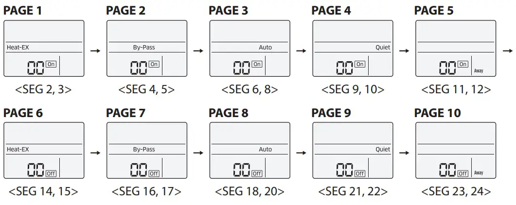
The total option codes are 24 digits . You can set six digits at a time and it isdistinguished by page number . Press the Timer button to go to the next page
![]() Caution
Caution
- Options can be set from SEG1 to SEG24
- SEG1, SEG7, SEG13, and SEG19 are page option so they cannot be set nor be displayed .
- SEG2 is the option type which cannot be set .
- When SEG2~SEG6 and SEG8~SEG12 are set, “On” is displayed and when SEG14~18 and SEG20~24 are set, “Off” is displayed
| SEG1 | SEG2 | SEG3 | SEG4 | SEG5 | SEG6 | SEG7 | SEG8 | SEG9 | SEG10 | SEG11 | SEG12 |
| 0 | X | X | X | X | X | 1 | X | X | X | X | X |
| SEG13 | SEG14 | SEG15 | SEG16 | SEG17 | SEG18 | SEG19 | SEG20 | SEG21 | SEG22 | SEG23 | SEG24 |
| 2 | X | X | X | X | X | 3 | X | X | X | X | X |
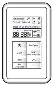
- The current SEG displayed can be distinguished by operation mode, On, and Off icon . SEG2~SEG6, SEG8~SEG12
- On(Heat-EX By Pass Auto Quiet Away) SEG14~SEG18, SEG20~24
- Off(Heat-EX By Pass Auto Quiet Away)
Note
- Address is displayed in hexadecimal . Refer to the table below
| Hexadecimal | Decimal | Hexadecimal | Decimal | Hexadecimal | Decimal | Hexadecimal | Decimal | Hexadecimal | Decimal |
| 00 | 0 | 10 | 16 | 20 | 32 | 30 | 48 | 40 | 64 |
| 01 | 1 | 11 | 17 | 21 | 33 | 31 | 49 | 41 | 65 |
| 02 | 2 | 12 | 18 | 22 | 34 | 32 | 50 | 42 | 66 |
| 03 | 3 | 13 | 19 | 23 | 35 | 33 | 51 | 43 | 67 |
| 04 | 4 | 14 | 20 | 24 | 36 | 34 | 52 | 44 | 68 |
| 05 | 5 | 15 | 21 | 25 | 37 | 35 | 53 | 45 | 69 |
| 06 | 6 | 16 | 22 | 26 | 38 | 36 | 54 | 46 | 70 |
| 07 | 7 | 17 | 23 | 27 | 39 | 37 | 55 | 47 | 71 |
| 08 | 8 | 18 | 24 | 28 | 40 | 38 | 56 | 48 | 72 |
| 09 | 9 | 19 | 25 | 29 | 41 | 39 | 57 | 49 | 73 |
| 0A | 10 | 1A | 26 | 2A | 42 | 3A | 58 | 4A | 74 |
| 0B | 11 | 1B | 27 | 2B | 43 | 3B | 59 | 4B | 75 |
| 0C | 12 | 1C | 28 | 2C | 44 | 3C | 60 | 4C | 76 |
| 0D | 13 | 1D | 29 | 2D | 45 | 3D | 61 | 4D | 77 |
| 0E | 14 | 1E | 30 | 2E | 46 | 3E | 62 | 4E | 78 |
| 0F | 15 | 1F | 31 | 2F | 47 | 3F | 63 | 4F | 79 |
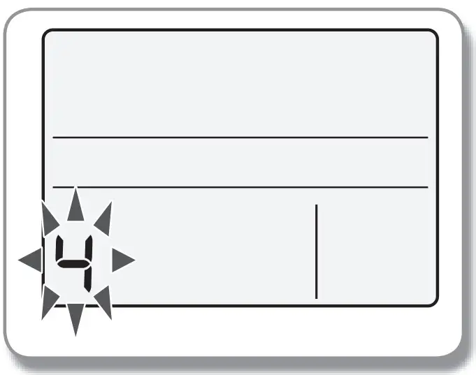
The example of setting ERV wired remote controller options
- Press the Mode and buttons at the same time for more than 3 seconds.
- When main menu is displayed, press the button to select no .5 .

- When main menu is displayed, press the
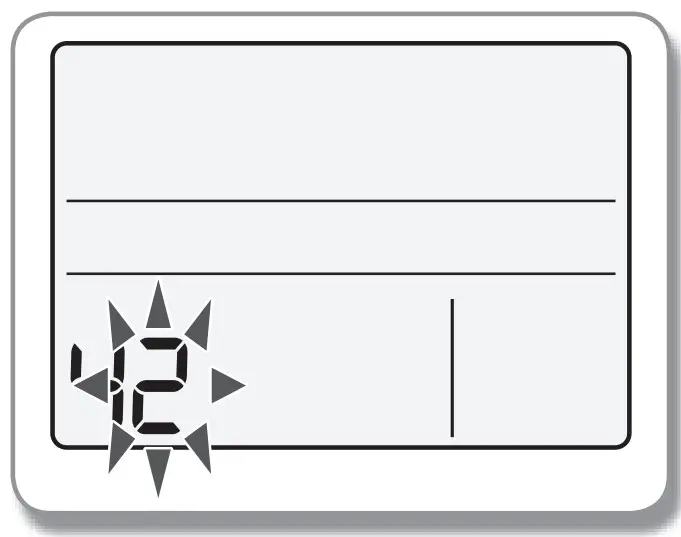
- Press the Away button to select the number you will set on the sub menu.
- Press the button to select no .1
- Press the
- Press the Away button to enter the data setting stage.
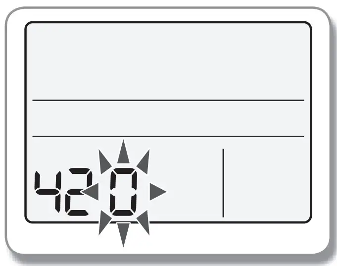
- When you enter the setting stage, the current setting is displayed .
- When you enter the setting stage, the current setting is displayed .
- Press the button to select no.1
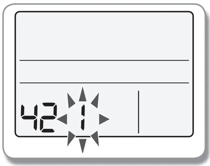
- The status of external interlock changes from “Disuse” to “Use” .
- The status of external interlock changes from “Disuse” to “Use” .
- Press the Set button to complete the option settings.
- Save the setting value and exit to sub menu .
- Save the setting value and exit to sub menu .
- Press the Timer button to exit to normal mode.