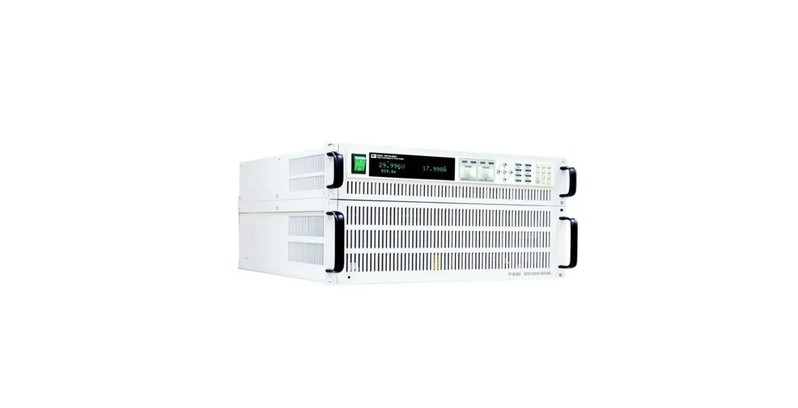
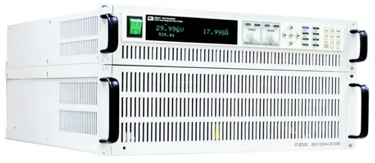
ITECH IT6500 Wide Range High Power DC Power Supply
APPLICATIONS
- Automotive Electronics
- Civil avionics
- Electric Vehicle Battery Test
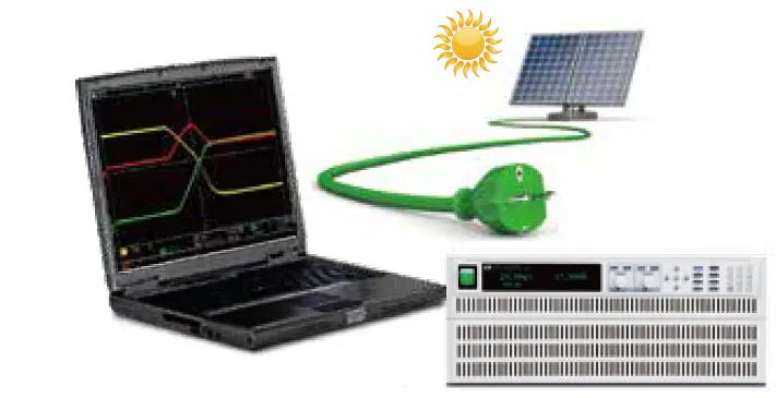
- Solar Panel I-V Curve Simulation
- Battery Simulation
- LED
Overcome the toughest high-power test challenges
With ITECH’s latest technology, the IT6500 series offers a full-featured high-performance power test solution. With a fast response, these DC power supplies provide users with a new level of power supply performance. From 800W to 6kW, the maximum output voltage and current is up to 1000V and 240A respectively. With its auto-ranging capability, it also has a super wide range of voltage and current applications. Users can choose the power supply that fits their testing requirements perfectly.
Choose the right power supplies that fit your test requirements
IT6502D/IT6512/IT6512A/ IT6513/IT6513A
Good performance and compact size, designed for general-purpose testing in R&D and production.
IT6500C/D series
High performance with stable output, designed for the automobile, green energy, high-speed testing, high-power testing, etc.
| 800W | IT6502D 80V/60A/800W | |||||
| 1200W | IT6512/A 80V/60A/1200W | IT6513/A 150V/30A/1200W | ||||
| 1800W | IT6512C/D 80V/120A/1800W | IT6513C/D 200V/60A/1800W | IT6514C/D 360V/30A/1800W | IT6515C/D 500V/20A/1800W | IT6516C/D 750V/15A/1800W | IT6517C/D 1000V/10A/1800W |
| 3kW | IT6522C/D 80V/120A/3kW | IT6523C/D 200V/60A/3kW | IT6524C/D 360V/30A/3kW | IT6525C/D 500V/20A/3kW | IT6526C/D 750V/15A/3kW | IT6527C/D 1000V/10A/3kW |
| 6kW | IT6532C/D 80V/240A/6kW | IT6533C/D 200V/120A/6kW | IT6534C/D 360V/60A/6kW | IT6535C/D 500V/40A/6kW | IT6536C/D 750V/30A/6kW | IT6537C/D 1000V/20A/6kW |
Fast response
Independent settable slew rate in different modes
IT6500C series can be used as a power supply and an electronic load. As a power supply, CV, CC, and CP modes are available. As an electronic load, CC and CP modes are available. IT6500C supports independent adjustable rise/fall time setting in different modes.
For every single model of the IT6500C/D series, no matter it is a single unit or multiple units paralleled together, the rise and fall time of each power supply in the IT6500C/D series are the same. Take IT6522C as an example:
- Within 30V voltage range, with 0-90% load, up and down speed <3ms
- Falling time of no load with voltage at full scale:
- Without a power dissipater unit, falling time <30ms
- With power dissipater unit, falling time <5ms
- Dynamic response time <3ms
- DC ratings of single unit IT6522C: 80V/120A/3000W
- Voltage ratings: 10V
- Current ratings: 120A
- Load Current: 0A

- DC ratings of single unit IT6522C: 80V/120A/3000W
- Voltage ratings: 10V
- Current ratings: 120A
- Load Current: 100A
No matter whether it is in the power supply mode (CV, CC, CP) or in the electronic load mode (CC, CP), the IT6500 series has adjustable rise and fall time, and the settable range is 1ms-24h.
Fast curve changing without overshoot CC & CV Priority Function
To conquer the demanding testing requirements existing for a long time in various applications, ITECH developed an innovative industry-leading CV & CC priority concept. The IT6500 is available for high-speed test applications without overshooting. Users can choose the desired output mode. Voltage high-speed mode or current no overshoot mode by choosing the loop response speed and loop operation mode. It is suitable for high-power integrated circuit tests, solar array simulations, and the transient simulation/characteristic of automotive electronics.
Fast voltage built with turn-on over range inrush current (CV-High, CC-Low, CV takes precedence)
Maintain excellent performance after paralleling
Built-in paralleling of multiple power supplies with even current distribution
IT6500C supports multiple power supplies paralleling together in master-slave mode. Even further it can ensure that each power supply equally shares the load current and they all remain in the desired mode. In the traditional sense, when paralleling power supplies together, different power supplies will operate in different operation modes.
For instance, when two sets of power supplies are paralleled together, one will offer a majority of current in CC mode, and the other will offer only a small part of the current in CV mode, which will degrade certain power supplies’ performance specifications. The even current distribution ability of the IT6500 ensures each power supply equally shares the load current without degrading the performance specifications. When paralleling multiple IT6500 the combined system has all the same functions as a standalone unit. That is a great way to add power flexibility to your test system. What is particularly unusual is that after the expansion of power, IT6500C can still maintain the excellent dynamic characteristics of the single unit to meet the I-V characteristic curve testing demanding a variety of high-power high-speed applications.
Low voltage & high current test
Standalone set IT6522C
- 80V,120A, 3000W
- Voltage ratings: 10V
- Current ratings: 120A
- Load current: 100A

8 sets of IT6522C paralleling together
- Voltage ratings: 10V
- Current ratings: 960A
- Load current: 800A
High voltage & low current test
Standalone set unit IT6522C
- 80V, 120A, 3000W
- Voltage ratings: 80V
- Current ratings: 120A
- Load current: 30A

8 sets of IT6522C paralleling together
- Voltage ratings: 80V
- Current ratings: 960A
- Load current: 300A

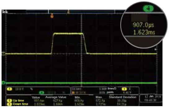
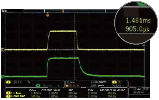
Dynamic response test
Standalone set IT6522C
80V, 120A, 3000W
- Voltage ratings: 10V
- Current ratings: 120A
- Load current:
- Level A=10A
- Level B=100A
- F=10 Hz

8 sets of IT6522C paralleling together
- Voltage ratings: 10V
- Current ratings: 960A
- Load current:
- Level A=100A
- Level B=800A
- F=10Hz

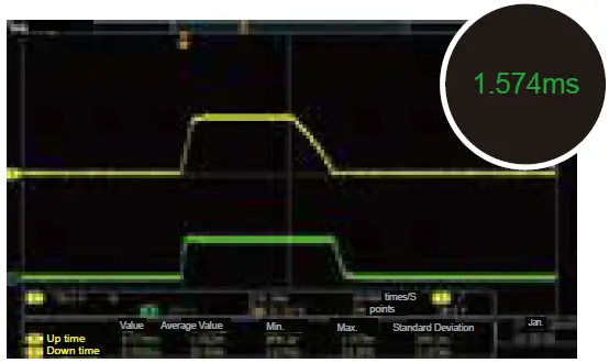
Figure: Voltage-Yellow, Current-Green
From the tests, we conclude:
- Voltage rise time: 8 units of IT6522C paralleling together, the voltage rise time is faster than single unit operation.
- Fall time: parallel units remain the same as a single unit.
- Dynamic response waveforms: parallel units remain the same as a single unit.
Simple programming on the front panel (List)
Similar to other modern ITECH products, the IT6500 series provides a user-friendly front panel for quick programming without the need for external software.
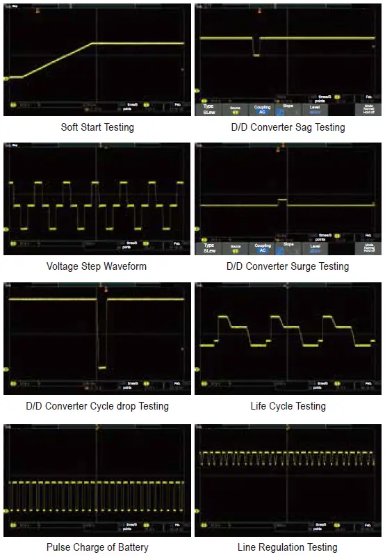
In list mode, the IT6500 series can store, recall and run the preset customized program sequences via front-panel programming. Users can edit the voltage/current value & the time of each step in advance and provide the power supply with a trigger signal. Then the preset sequences/waveform will be executed automatically according to the defined LIST. That’s especially suitable for the applications such as DC / DC converters, inverters voltage drop tests, engine start-up simulations, battery charging / discharging tests, product life cycle tests, aircraft tests, etc.
Waveforms programmed with IT6500 series by engineers
Functions for special applications
Programmable output impendence
In the battery charging and discharging test, the changes in internal resistance should be taken into account. For enhancing test precision, the IT6500C series power supply provides a built-in internal resistance setting function that can simulate battery operation status in real-case.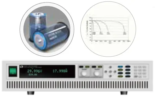
Multiple actual working status simulations of batteries
Solar panel I-V curve simulation function
IT6500C series high-power DC power supply is equipped with SAS1000 solar array simulation software, which can accurately simulate the solar array I-V curve. With built-in EN50530 / Sandia / NB/T32004 / CGC/GF004 / CGC/GF035 SAS module. Users can set the parameters to simulate I-V curve characteristic output and generate reports. These benefit much in a test of the static & dynamic maximum power tracking performance of photovoltaic inverters.
SAS1000 solar array simulation software is available for choice
Built-in standard automotive power network voltage curves
The automobile electronics devices must tolerate the dropouts or surges from power turn-on or turn-off transient. For these tests, it is necessary to simulate the worst-case power transient conditions. IT6500C series power supply provides built-in DIN40839, ISO-16750-2, SAEJ1113-11, LV124 and ISO21848 testing curves. Users can select any built-in curve to do the DUT performance test directly according to their demand. 12V, 24V, and 48V are available for choice.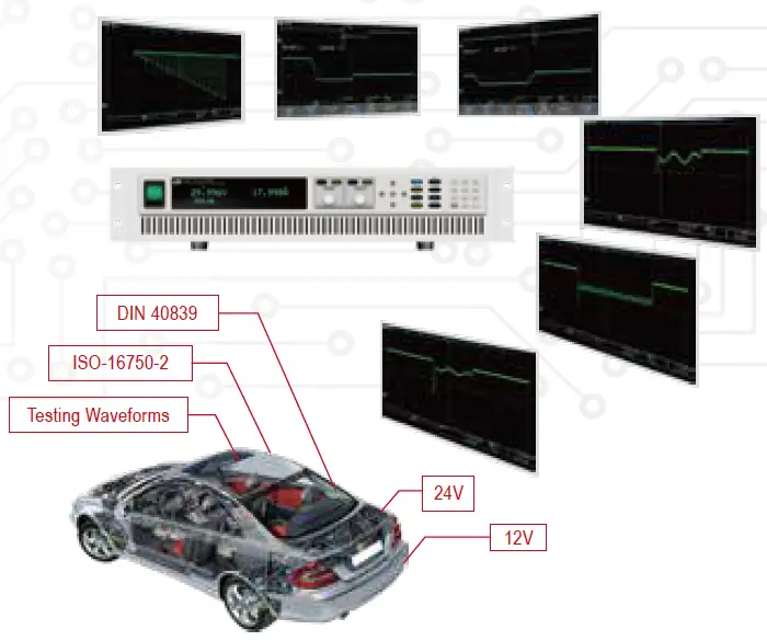
Multiple built-in interfaces
In conventional high-power test instruments, extra interfaces add cost. In the IT6500 series, all the implemented interfaces are built-in standards. Simplifying the configuration process and adding flexibility to change the interface used without adding additional cost.
| Cost saving | IT6500C | IT6500D | IT6512 IT6513 | IT6502D IT6512A IT6513A |
| Analog control interfaces | √ | √ | √ | √ |
| USB | √ | √ | √ | √ |
| RS232 | √ | √ | √ | √ |
| RS485 | – | – | √ | √ |
| LAN | √ | √ | – | – |
| CAN | √ | √ | – | – |
Full protections
Integrating protection measures into test instruments is critical and high cost, especially in high-power tests. To provide full protection for DUTs, the IT6500 series integrate multiple fast protection measures.
These protection capabilities include:
- CC & CV Priority Function to avoid unwanted overshoot
- Power Supply mode: OVP, OCP, OPP
- Electronic Load mode: OCP, OPP, OTP (IT6500C)
- Anti-reverse protection (optional)
- Turn-off protection
- Under voltage protection (UVP)
Specification Parameters
| Parameter | IT6502D | IT6512 | IT6512A | IT6513 | IT6513A | |
| Output Rating (0°C~40°C) | Voltage Current Power | 0~80V 0~60A 0~800W | 0~80V 0~60A 0~1200W | 0~80V 0~60A 0~1200W | 0~150V 0~30A 0~1200W | 0~150V 0~30A 0~1200W |
| Load Regulation Voltage | <0.01%+8mV ≤0.1%+10mA | <0.01%+8mV ≤0.1%+10mA | <0.01%+8mV ≤0.1%+10mA | <0.05%+30mV ≤0.1%+30mA | <0.05%+30mV ≤0.1%+30mA | |
| ±(%of Output+Offset) | Current | |||||
| Line Regulation ±(%of Output+Offset) | Voltage Current | <0.02%+2mV <0.02%+2mA | <0.02%+2mV <0.02%+2mA | <0.02%+2mV <0.02%+2mA | <0.02%+20mV <0.02%+10mA | <0.02%+20mV <0.02%+10mA |
| Setup Resolution | Voltage Current | 1mV 1mA | 1mV 1mA | 1mV 1mA | 3mV 1mA | 3mV 1mA |
| Readback Resolution | Voltage Current | 1mV 1mA | 1mV 1mA | 1mV 1mA | 3mV 1mA | 3mV 1mA |
| Setup Accuracy *1 (Within 12 months,25°C±5°C) ±(%of Output+Offset) | Voltage Current | ≤0.02%+30mV ≤0.1%+0.1%FS | ≤0.02%+30mV ≤0.1%+0.1%FS | ≤0.02%+30mV ≤0.1%+0.1%FS | ≤0.05%+30mV ≤0.2%+0.1%FS | ≤0.05%+30mV ≤0.2%+0.1%FS |
| Readback Accuracy *2 (Within 12 months,25°C±5°C) ±(%of Output+Offset) | Voltage Current | 0.02%+30mV ≤0.1%+0.1%FS | 0.02%+30mV ≤0.1%+0.1%FS | ≤0.02%+30mV ≤0.1%+0.1%FS | <0.05%+30mV ≤0.2%+0.1%FS | 0.05%+30mV ≤0.2%+0.1%FS |
| Ripple (20Hz-20MHz) | Voltage Current | ≤30mVp-p ≤20mArms | ≤30mVp-p 10mArms | ≤30mVp-p ≤20mArms | ≤60mVp-p ≤40mArms | ≤60mVp-p 40mArms |
| Setting Temperature Coefficient ±(%of Output+Offset) | Voltage Current | ≤0.02%+30mV ≤0.05%+10mA | 0.02%+30mV ≤0.05%+10mA | ≤0.02%+30mV ≤0.05%+10mA | <0.02%+30mV ≤0.05%+10mA | 0.02%+30mV ≤0.05%+10mA |
| Readback Temperature Coefficient ±(%of Output+Offset) | Voltage Current | ≤0.02%+30mV ≤0.05%+5mA | 0.02%+30mV ≤0.05%+5mA | ≤0.02%+30mV ≤0.05%+5mA | <0.02%+30mV ≤0.05%+5mA | 0.02%+30mV ≤0.05%+5mA |
| Dimension (mm) | 415mmW×44mmH×500mmD | |||||
| Parameter | IT6512C | IT6512D | IT6522C | IT6522D | IT6532C | IT6532D | |
| Output Rating (0°C~40°C) | Voltage Current Power | 0~80V 0~120A 0~1800W | 0~80V 0~120A 0~1800W | 0~80V 0~120A 0~3000W | 0~80V 0~120A 0~3000W | 0~80V 0~240A 0~6kW | 0~80V 0~240A 0~6kW |
| Programmable output resistance | 0~3.556Ω | – | 0~2.133Ω | – | 0~1.067Ω | – | |
| Load Regulation ±(%of Output+Offset) | Voltage Current | ≤0.01%+30mV ≤0.05%+30mA | ≤0.01%+30mV ≤0.05%+60mA | ||||
| Line Regulation ±(%of Output+Offset) | Voltage Current | ≤0.01%+10mV ≤0.01%+15mA | ≤0.01%+10mV ≤0.01%+30mA | ||||
| Setup Resolution | Voltage Current | 10mV 10mA | 100mV 10mA | ||||
| Readback Resolution | Voltage Current | 10mV 10mA | 100mV 10mA | ||||
| Setup Accuracy *1 (Within 12 months,25 °C±5°C) ±(%of Output+Offset) | Voltage Current | ≤0.05%+30mV ≤0.2%+120mA | ≤0.05%+30mV ≤0.2%+240mA | ||||
| Readback Accuracy *2 (Within 12 months,25°C±5°C) ±(%of Output+Offset) | Voltage Current | ≤0.05%+30mV ≤0.2%+120mA | ≤0.05%+30mV ≤0.2%+240mA | ||||
| Ripple (20Hz-20MHz) | Voltage Current | ≤80mVp-p ≤0.05%+60mArms | ≤80mVp-p ≤0.05%+120mArms | ||||
| Rise time (no load) *3 | Voltage | ≤5ms | ≤30ms | ≤5ms | ≤30ms | ≤5ms | ≤30ms |
| Fall time (full load) *3 | Voltage | ≤10ms | ≤20ms | ≤10ms | ≤20ms | ≤10ms | ≤20ms |
| Number of Power Dissipators in Parallel | ≤3 | – | ≤3 | – | ≤6 | – | |
| Dimension (mm) | 483mmW×105.4mmH×640.8mmD | 483mmW×194mmH×640.8mmD | |||||
| Parameter | IT6513C | IT6513D | IT6523C | IT6523D | IT6533C | IT6533D | |
| Output Rating (0°C~40°C) | Voltage Current Power | 0~200V 0~60A 0~1800W | 0~200V 0~60A 0~1800W | 0~200V 0~60A 0~3000W | 0~200V 0~60A 0~3000W | 0~200V 0~120A 0~6kW | 0~200V 0~120A 0~6kW |
| Programmable output resistance | 0~22.222Ω | – | 0~13Ω | – | 0~6.666Ω | – | |
| Load Regulation ±(%of Output+Offset) | Voltage Current | ≤0.01%+50mV ≤0.05%+20mA | ≤0.01%+50mV ≤0.05%+40mA | ||||
| Line Regulation ±(%of Output+Offset) | Voltage Current | ≤0.01%+20mV ≤0.01%+10mA | ≤0.01%+20mV ≤0.01%+20mA | ||||
| Setup Resolution | Voltage Current | 10mV 10mA | 10mV 10mA | ||||
| Readback Resolution | Voltage Current | 10mV 10mA | 10mV 10mA | ||||
| Setup Accuracy *1 (Within 12 months,25°C±5°C) ±(%of Output+Offset) | Voltage Current | ≤0.05%+100mV ≤0.2%+60mA | ≤0.05%+100mV ≤0.2%+120mA | ||||
| Readback Accuracy *2 (Within 12 months,25°C±5°C) ±(%of Output+Offset) | Voltage Current | ≤0.05%+100mV ≤0.2%+60mA | ≤0.05%+100mV ≤0.2%+120mA | ||||
| Ripple (20Hz-20MHz) | Voltage Current | ≤200mVp-p ≤50mArms | ≤200mVp-p ≤100mArms | ||||
| Rise time (no load) *3 | Voltage | ≤15ms | ≤100ms | ≤15ms | ≤100ms | ≤15ms | ≤100ms |
| Fall time (full load) *3 | Voltage | ≤15ms | ≤20ms | ≤15ms | ≤20ms | ≤15ms | ≤20ms |
| Number of Power Dissipators in Parallel | ≤3 | – | ≤3 | – | ≤6 | – | |
| Dimension (mm) | 483mmW×105.4mmH×640.8mmD | 483mmW×194mmH×640.8mmD | |||||
| Parameter | IT6514C | IT6514D | IT6524C | IT6524D | IT6534C | IT6534D | |
| Output Rating (0°C~40°C) | Voltage Current Power | 0~360V 0~30A 0~1800W | 0~360V 0~30A 0~1800W | 0~360V 0~30A 0~3000W | 0~360V 0~30A 0~3000W | 0~360V 0~60A 0~6kW | 0~360V 0~60A 0~6kW |
| Programmable output resistance | 0~72Ω | – | 0~43.2Ω | – | 0~21.6Ω | – | |
| Load Regulation ±(%of Output+Offset) | Voltage Current | ≤0.01%+135mV ≤0.05%+15mA | ≤0.01%+135mV ≤0.05%+30mA | ||||
| Line Regulation ±(%of Output+Offset) | Voltage Current | ≤0.01%+40mV ≤0.01%+5mA | ≤0.01%+40mV ≤0.01%+10mA | ||||
| Setup Resolution | Voltage Current | 10mV 10mA | 10mV 10mA | ||||
| Readback Resolution | Voltage Current | 10mV 10mA | 10mV 10mA | ||||
| Setup Accuracy *1 (Within 12 months,25°C±5°C) ±(%of Output+Offset) | Voltage Current | ≤0.05%+135mV ≤0.2%+30mA | ≤0.05%+135mV ≤0.2%+60mA | ||||
| Readback Accuracy *2 (Within 12 months,25°C±5°C) ±(%of Output+Offset) | Voltage Current | ≤0.05%+135mV ≤0.2%+30mA | ≤0.05%+135mV ≤0.2%+60mA | ||||
| Ripple (20Hz-20MHz) | Voltage Current | ≤360mVp-p ≤0.05%+30mArms | ≤360mVp-p ≤0.05%+60mArms | ||||
| Rise time (no load) *3 | Voltage | ≤50ms | ≤250ms | ≤50ms | ≤250ms | ≤50ms | ≤250ms |
| Fall time (full load) *3 | Voltage | ≤55ms | ≤70ms | ≤55ms | ≤70ms | ≤55ms | ≤70ms |
| Number of Power Dissipators in Parallel | ≤3 | – | ≤3 | – | ≤6 | – | |
| Dimension (mm) | 483mmW×105.4mmH×640.8mmD | 483mmW×194mmH×640.8mmD | |||||
- Setup Accuracy refers to users’ use of panel keys or communication commands to achieve setup accuracy; when using external analog programming, the programming accuracy is 1%
- Readback Accuracy refers to users using panel display or communication commands to achieve readback accuracy; when using external analog monitoring, the monitor accuracy is 1%
- Rise and Fall Time refers to the settling time of setup value from one value to another using the internal standard power dissipator in the ON state.
| Parameter | IT6515C | IT6515D | IT6525C | IT6525D | IT6535C | IT6535D | |
| Output Rating (0°C~40°C) | Voltage Current Power | 0~500V 0~20A 0~1800W | 0~500V 0~20A 0~1800W | 0~500V 0~20A 0~3000W | 0~500V 0~20A 0~3000W | 0~500V 0~40A 0~6kW | 0~500V 0~40A 0~6kW |
| Programmable output resistance | 0~138.88Ω | – | 0~83.33Ω | – | 0~41.66Ω | – | |
| Load Regulation ±(%of Output+Offset) | Voltage Current | ≤0.01%+100mV ≤0.05%+20mA | ≤0.01%+100mV ≤0.05%+40mA | ||||
| Line Regulation ±(%of Output+Offset) | Voltage Current | ≤0.01%+50mV ≤0.01%+5mA | ≤0.01%+50mV ≤0.01%+10mA | ||||
| Setup Resolution | Voltage Current | 100mV 10mA | 100mV 10mA | ||||
| Readback Resolution | Voltage Current | 100mV 10mA | 100mV 10mA | ||||
| Setup Accuracy *1 (Within 12 months,25°C±5°C) ±(%of Output+Offset) | Voltage Current | ≤0.05%+200mV ≤0.2%+20mA | ≤0.05%+200mV ≤0.2%+40mA | ||||
| Readback Accuracy *2 (Within 12 months,25°C±5°C) ±(%of Output+Offset) | Voltage Current | ≤0.05%+200mV ≤0.2%+20mA | ≤0.05%+200mV ≤0.2%+40mA | ||||
| Ripple (20Hz-20MHz) | Voltage Current | ≤500mVp-p ≤40mArms | ≤500mVp-p ≤80mArms | ||||
| Rise time (no load) *3 | Voltage | ≤40ms | ≤200ms | ≤40ms | ≤200ms | ≤40ms | ≤200ms |
| Fall time (full load) *3 | Voltage | ≤25ms | ≤30ms | ≤25ms | ≤30ms | ≤25ms | ≤30ms |
| Number of Power Dissipators in Parallel | ≤3 | – | ≤3 | – | ≤6 | – | |
| Dimension (mm) | 483mmW×105.4mmH×640.8mmD | 483mmW×194mmH×640.8mmD | |||||
| Parameter | IT6516C | IT6516D | IT6526C | IT6526D | IT6536C | IT6536D | |
| Output Rating (0°C~40°C) | Voltage Current Power | 0~750V 0~15A 0~1800W | 0~750V 0~15A 0~1800W | 0~750V 0~15A 0~3000W | 0~750V 0~15A 0~3000W | 0~750V 0~30A 0~6kW | 0~750V 0~30A 0~6kW |
| Programmable output resistance | 0~312.5Ω | – | 0~188Ω | – | 0~93.75Ω | – | |
| Load Regulation ±(%of Output+Offset) | Voltage Current | ≤0.01%+200mV ≤0.05%+15mA | ≤0.01%+200mV ≤0.05%+30mA | ||||
| Line Regulation ±(%of Output+Offset) | Voltage Current | ≤0.01%+75mV ≤0.1%+5mA | ≤0.01%+75mV ≤0.1%+10mA | ||||
| Setup Resolution | Voltage Current | 100mV 10mA | 100mV 10mA | ||||
| Readback Resolution | Voltage Current | 100mV 10mA | 100mV 10mA | ||||
| Setup Accuracy *1 (Within 12 months,25 °C±5°C) ±(%of Output+Offset) | Voltage Current | ≤0.05%+300mV ≤0.2%+15mA | ≤0.05%+300mV ≤0.2%+30mA | ||||
| Readback Accuracy *2 (Within 12 months,25°C±5°C) ±(%of Output+Offset) | Voltage Current | ≤0.05%+300mV ≤0.2%+15mA | ≤0.05%+300mV ≤0.2%+30mA | ||||
| Ripple (20Hz-20MHz) | Voltage Current | ≤750mVp-p ≤30mArms | ≤750mVp-p ≤60mArms | ||||
| Rise time (no load) *3 | Voltage | ≤50ms | ≤250ms | ≤50ms | ≤250ms | ≤50ms | ≤250ms |
| Fall time (full load) *3 | Voltage | ≤20ms | ≤20ms | ≤20ms | ≤20ms | ≤20ms | ≤20ms |
| Number of Power Dissipators in Parallel | ≤3 | – | ≤3 | – | ≤6 | – | |
| Dimension (mm) | 483mmW×105.4mmH×640.8mmD | 483mmW×194mmH×640.8mmD | |||||
| Parameter | IT6517C | IT6517D | IT6527C | IT6527D | IT6537C | IT6537D | |
| Output Rating (0°C~40°C) | Voltage Current Power | 0~1000V 0~10A 0~1800W | 0~1000V 0~10A 0~1800W | 0~1000V 0~10A 0~3000W | 0~1000V 0~10A 0~3000W | 0~1000V 0~20A 0~6kW | 0~1000V 0~20A 0~6kW |
| Programmable output resistance | 0~555.555Ω | – | 0~333.333Ω | – | 0~166.666Ω | – | |
| Load Regulation ±(%of Output+Offset) | Voltage Current | ≤0.01%+375mV ≤0.05%+5mA | ≤0.01%+375mV ≤0.05%+10mA | ||||
| Line Regulation ±(%of Output+Offset) | Voltage Current | ≤0.01%+100mV ≤0.01%+5mA | ≤0.01%+100mV ≤0.01%+10mA | ||||
| Setup Resolution | Voltage Current | 100mV 1mA | 100mV 1mA | ||||
| Readback Resolution | Voltage Current | 100mV 1mA | 100mV 1mA | ||||
| Setup Accuracy *1 (Within 12 months,25°C±5°C) ±(%of Output+Offset) | Voltage Current | ≤0.05%+375mV ≤0.2%+10mA | ≤0.05%+375mV ≤0.2%+20mA | ||||
| Readback Accuracy *2 (Within 12 months,25°C±5°C) ±(%of Output+Offset) | Voltage Current | ≤0.05%+375mV ≤0.2%+10mA | ≤0.05%+375mV ≤0.2%+20mA | ||||
| Ripple (20Hz-20MHz) | Voltage Current | ≤1Vp-p ≤0.05%+10mArms | ≤1Vp-p ≤0.05%+20mArms | ||||
| Rise time (no load) *3 | Voltage | ≤70ms | ≤300ms | ≤70ms | ≤300ms | ≤70ms | ≤300ms |
| Fall time (full load) *3 | Voltage | ≤30ms | ≤30ms | ≤30ms | ≤30ms | ≤30ms | ≤30ms |
| Number of Power Dissipators in Parallel | ≤3 | – | ≤3 | – | ≤6 | – | |
| Dimension (mm) | 483mmW×105.4mmH×640.8mmD | 483mmW×194mmH×640.8mmD | |||||
- Setup Accuracy refers to users’ use of panel keys or communication commands to achieve setup accuracy; when using external analog programming, the programming accuracy is 1%
- Readback Accuracy refers to users using panel display or communication commands to achieve readback accuracy; when using external analog monitoring, the monitor accuracy is 1%
- Rise and Fall Time refers to the settling time of setup value from one value to another using the internal standard power dissipator in the ON state
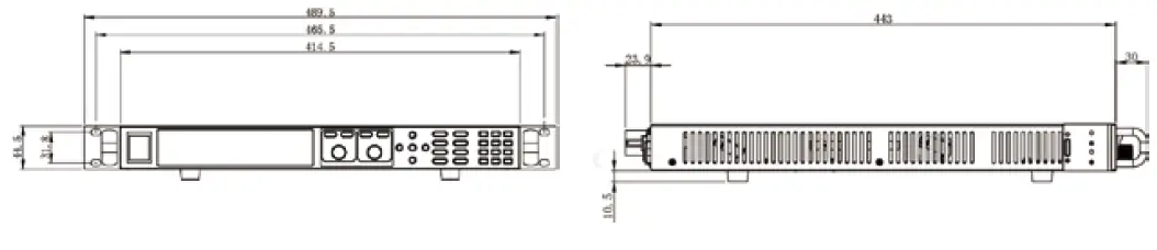
Models
IT6512/IT6513/IT6512A/IT6513A/IT6502D Model
Machine size
- Width: 414.5mm
- Height: 44.5mm
- Depth: 500mm
Detailed Dimension
This information is subject to change without notice. For more information, please contact ITECH.
Taipei
Add: No.918, Zhongzheng Rd., Zhonghe Dist., New Taipei City
235, Taiwan
Web: www.itechate.com
TEL: +886-3-6684333
E-mail: [email protected].
Factory I
Add: No.108, XiShanqiao Nanlu, Nanjing city, 210039, China
TEL: +86-25-52415098
Web: www.itechate.com
Factory II
Add: No.150, Yaonanlu, Meishan Cun, Nanjing city, 210039, China
TEL: +86-25-52415099
Web: www.itechate.com


![Itech Power Meter [it9121, It9121h, It9121c, It9121e] User Manual](https://static-data1.manualsee.com/1/img/72/17006/2020/12/iTech-Power-meter.jpg "Itech Power Meter [it9121, It9121h, It9121c, It9121e] User Manual")
