![]()
Operation manual
Daikin Altherma 3 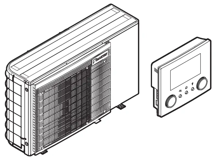
| EBLA04E2V3 EBLA06E2V3 EBLA08E2V3 EBLA04E23V3 EBLA06E23V3 EBLA08E23V3 | EDLA04E2V3 EDLA06E2V3 EDLA08E2V3 EDLA04E23V3 EDLA06E23V3 EDLA08E23V3 |
About this document
Thank you for purchasing this product. Please:
- Read the documentation carefully before operating the user interface to ensure the best possible performance.
- Request the installer to inform you about the settings that he used to configure your system. Check if he has filled in the installer settings tables. If NOT, request him to do so.
- Keep the documentation for future reference.
Target audience
End users
The documentation set
This document is part of a documentation set. The complete set consists of:
General safety precautions:
- Safety instructions that you must read before installing
- Format: Paper (in the box of the outdoor unit)
Operation manual:
Quick guide for basic usage
Format: Paper (in the box of the outdoor unit)
User reference guide:
- Detailed step-by-step instructions and background information for basic and advanced usage
- Format: Digital files on http://www.daikineurope.com/supportand-manuals/product-information/
Installation manual:
- Installation instructions
- Format: Paper (in the box of the outdoor unit)
Installer reference guide:
- Preparation of the installation, good practices, reference data, …
- Format: Digital files on http://www.daikineurope.com/supportand-manuals/product-information/
Addendum book for optional equipment:
- Additional info about how to install optional equipment
- Format: Paper (in the box of the outdoor unit) + Digital files on http://www.daikineurope.com/support-and-manuals/productinformation/
The latest revisions of the supplied documentation may be available on the regional Daikin website or via your installer.
The original documentation is written in English. All other languages are translations.
ONECTA app
If set up by your installer, you can use the ONE CTA app to control and monitor the status of your system. For more information, see:
http://www.onlinecontroller.daikineurope.com/

Breadcrumbs
Breadcrumbs (example: [4.3]) help you to locate where you are in the menu structure of the user interface.
| 1 | To enable the breadcrumbs: In the home screen or main menu screen, press the help button. The breadcrumbs appear in the top left corner of the screen. | ‽ |
| 2 | To disable the breadcrumbs: Press the help button again. | ‽ |
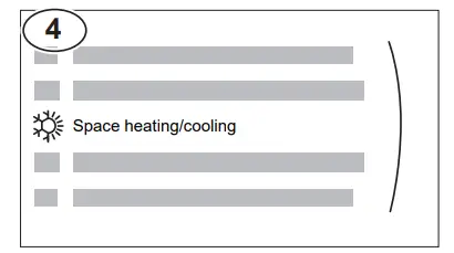
This document also mentions these breadcrumbs. Example:
| 1 | Go to [4.3]: Space heating/cooling > Operation range. |
This means:
| 1 | Starting from the home screen, turn the left dial and go to Space heating/cooling.
| |
| 2 | Press the left dial to enter the submenu. | |
| 3 | Turn the left dial and go to Operation range.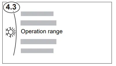 | |
| 4 | Press the left dial to enter the submenu. |
User safety instructions
Always observe the following safety instructions and regulations
2.1 General
![]() WARNING
WARNING
If you are NOT sure how to operate the unit, contact your installer.![]() WARNING
WARNING
This appliance can be used by children aged 8 years and above and persons with reduced physical, sensory or mental capabilities or lack of experience and knowledge if they have been given supervision or instruction concerning the use of the appliance in a safe way and understand the hazards involved. Children SHALL NOT play with the appliance. Cleaning and user maintenance SHALL NOT be made by children without supervision.
![]() WARNING
WARNING
To prevent electrical shocks or fire:
- Do NOT rinse the unit.
- Do NOT operate the unit with wet hands.
- Do NOT place any objects containing water on the unit.
![]() CAUTION
CAUTION
- Do NOT place any objects or equipment on top of the unit.
- Do NOT sit, climb or stand on the unit.
- Units are marked with the following symbol:
 This means that electrical and electronic products may NOT be mixed with unsorted household waste. Do NOT try to dismantle the system yourself: the dismantling of the system and treatment of the refrigerant, oil, and other parts MUST be done by an authorized installer and MUST comply with applicable legislation. Units MUST be treated at a specialized treatment facility for reuse, recycling, and recovery. By ensuring this product is disposed of correctly, you will help to prevent potential negative consequences for the environment and human health. For more information, contact your installer or local authority.
 - Batteries are marked with the following symbol:
 This means that the batteries may NOT be mixed with unsorted household waste. If a chemical symbol is printed beneath the symbol, this chemical symbol means that the battery contains a heavy metal above a certain concentration.
Possible chemical symbols are Pb: lead (>0.004%).
Waste batteries MUST be treated at a specialized treatment facility for reuse. By ensuring waste batteries are disposed of correctly, you will help to prevent potential negative consequences for the environment and human health.
Instructions for safe operation
![]() WARNING: MILDLY FLAMMABLE MATERIAL
WARNING: MILDLY FLAMMABLE MATERIAL
The refrigerant inside this unit is mildly flammable.![]() WARNING
WARNING
The appliance shall be stored so as to prevent mechanical damage and in a well-ventilated room without continuously operating ignition sources
About the system
(example: open flames, an operating gas appliance, or an operating electric heater).
![]() WARNING
WARNING
- Do NOT pierce or burn refrigerant cycle parts.
- Do NOT use cleaning materials or means to accelerate the defrosting process other than those recommended by the manufacturer.
- Be aware that the refrigerant inside the system is odorless.
![]() WARNING
WARNING
- The refrigerant inside the unit is mildly flammable but normally does NOT leak. If the refrigerant leaks in the room and comes in contact with fire from a burner, a heater, or a cooker, this may result in fire or the formation of harmful gas.
- Turn OFF any combustible heating devices, ventilate the room, and contact the dealer where you purchased the unit.
- Do NOT use the unit until a service person confirms that the part from which the refrigerant leaked has been repaired.
![]() WARNING
WARNING
Air purging heat emitters or collectors. Before you purge air from heat emitters or collectors, check if ![]() or
or ![]() is displayed on the home screen of the user interface.
is displayed on the home screen of the user interface.
- If not, you can purge the air immediately.
- If yes, make sure that the room where you want to purge air is sufficiently ventilated. Reason: Refrigerant might leak into the water circuit, and subsequently into the room when you purge air from the heat emitters or collectors.
Depending on the system layout, the system can:
- Heat up a space
- Cool down a space
- Produce domestic hot water (if a DHW tank is installed)
 INFORMATION
Cooling is only applicable in the case of reversible models. INFORMATION
If underfloor heating is installed in the main zone, then in cooling mode the main zone can only provide refreshment. Real cooling is then NOT allowed.
Components in a typical system layout
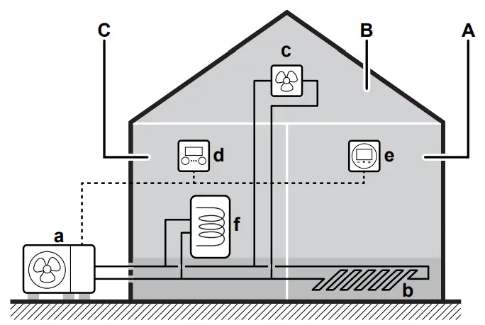
The Main zone. Example: Living room.
B Additional zone. Example: Bedroom.
C Technical room. Example: Garage.
an Outdoor unit heat pump
b Underfloor heating
c Heat pump convectors or fan coil units
d User interface
e Dedicated Human Comfort Interface (BRC1HHDA used as room thermostat)
f Domestic hot water (DHW) tank
Quick guide
User permission level
The amount of information you can read and edit in the menu structure depends on your user permission level:
- User: Standard mode
- Advanced user: You can read and edit more information
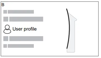
To change the user permission level
| 1 | Go to [B]: User profile.
| |
| 2 | Enter the applicable pin code for the user permission level. | _ |
| ▪ Browse through the list of digits and change the selected digit. | ||
| ▪ Move the cursor from left to right. | ||
| ▪ Confirm the pin code and proceed. |
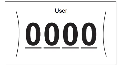
User pin code
The User pin code is 0000.
Advanced user pin code
The Advanced user pin code is 1234. Additional menu items for the user are now visible.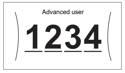
4.2 Space heating/cooling
To turn space heating/cooling operation ON or OFF
![]() NOTICE
NOTICE
Room frost protection. Even if you turn OFF the space heating/cooling operation ([C.2]: Operation > Space heating/cooling), the room frost protection operation –if enabled– can still activate. However, for leaving water temperature control and external room thermostat control, the protection is NOT guaranteed.
![]() NOTICE
NOTICE
Water pipe freeze prevention. Even if you turn OFF the space heating/cooling operation ([C.2]: Operation > Space heating/cooling), water pipe freeze prevention – if enabled– will remain active.
| 1 | Go to [C.2]: Operation > Space heating/cooling.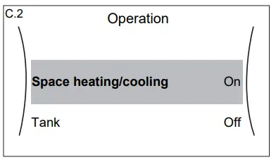 | |
| 2 | Set operation to On or Off. |
To change the desired room temperature
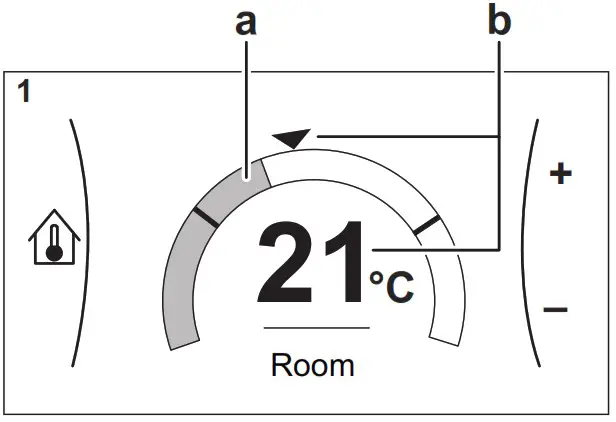
During room temperature control, you can use the room temperature setpoint screen to read out and adjust the desired room temperature
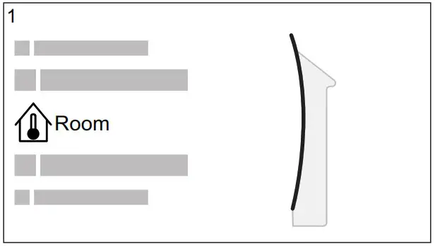
| 1 | Go to [1]: Room.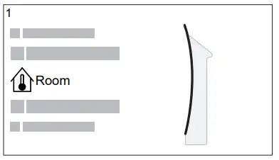 |
| 2 | Adjust the desired room temperature.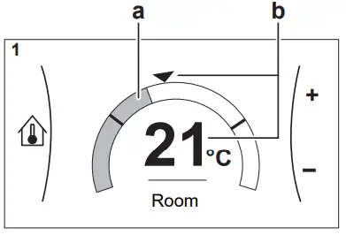 an Actual room temperature b Desired room temperature |
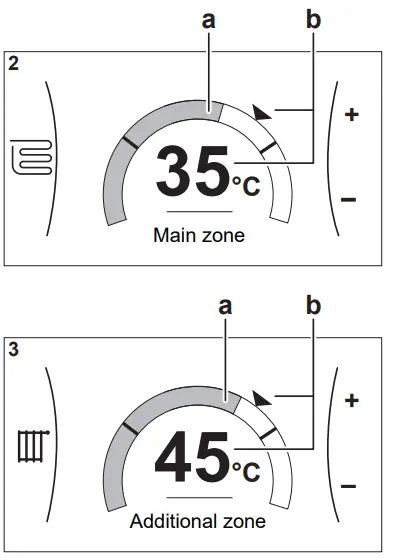
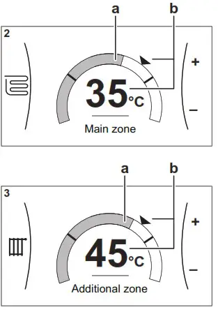
To change the desired leaving water temperature
You can use the leaving water temperature setpoint screen to read out and adjust the desired leaving water temperature.
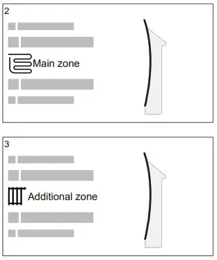
| 1 | Go to [2]: Main zone or [3]: Additional zone.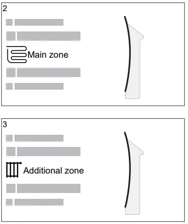 | |
| 2 | Adjust the desired leaving water temperature.
|
To change the weather-dependent curve for the space heating/cooling zones
- Go to the applicable zone:
Zone Go to … Main zone – Heating [2.5] Main zone > Heating WD curve Main zone – Cooling [2.6] Main zone > Cooling WD curve Additional zone – Heating [3.5] Additional zone > Heating WD curve Additional zone – Cooling [3.6] Additional zone > Cooling WD curve - Change the weather-dependent
Operation
There are 2 types of WD curves: slope-offset curve (default), and 2-point curve. If needed, you can change the type in [2. E] the Main zone > WD curve type. The way to adjust the curve depends on the type.
Slope-offset curve
Slope. When the slope is changed, the new preferred temperature at X1 is unequally higher than the preferred temperature at X2. 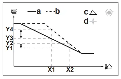 Offset. When the offset is changed, the new preferred temperature at X1 is equally higher than the preferred temperature at X2.
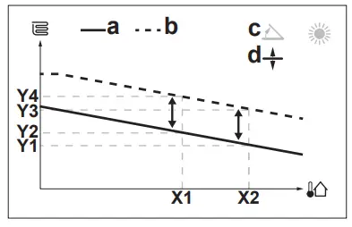 X1, X2 Outdoor ambient temperature
Y1~Y4 Desired to leave water temperature
a WD curve before changes
b WD curve after changes
c Slope
d Offset
| Possible actions on this screen | |
| Select slope or offset. | |
| Increase or decrease the slope/offset. | |
| When the slope is selected: set the slope and go to offset. When the offset is selected: set offset. | |
| Confirm changes and return to the submenu. | |
2-points curve
X1, X2 Outdoor ambient temperature
Y1, Y2 Desired to leave water temperature
| Possible actions on this screen | |
| Go through the temperatures. | |
| Change the temperature. | |
| Go to the next temperature. | |
| Confirm changes and proceed. | |
More information
For more information, see also:
- “5.4 Turning operation ON or OFF” [4 11]
- “5.6 Space heating/cooling control” [4 12]
- “5.8 Schedule screen: Example” [4 14]
- “5.9 Weather-dependent curves” [4 15]
- User reference guide
Domestic hot water
To turn tank heating operation ON or OFF
![]() NOTICE
NOTICE
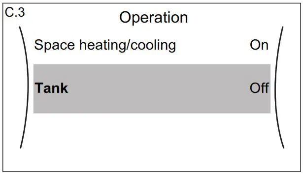
Disinfection mode. Even if you turn OFF the tank heating operation ([C.3]: Operation > Tank), disinfection mode will remain active. However, if you turn it OFF while disinfection is running, an AH error occurs.
| 1 | Go to [C.3]: Operation > Tank.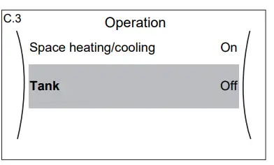 | |
| 2 | Set operation to On or Off. |
To change the tank temperature setpoint
In Reheat only mode, you can use the tank temperature setpoint screen to read out and adjust the domestic hot water temperature.
| 1 | Go to [5]: Tank.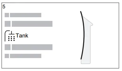 | |
| 2 | Adjust the domestic hot water temperature.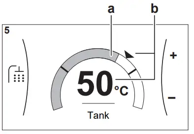 a Actual domestic hot water temperature b Desired domestic hot water temperature |
In other modes, you can only view the setpoint screen but not modify it. Instead, you can modify the settings for the Comfort setpoint [5.2], Eco setpoint [5.3] and Reheat setpoint [5.4].
More information
For more information, see also:
- “5.4 Turning operation ON or OFF” [4 11]
- “5.7 Domestic hot water control” [4 13]
- “5.8 Schedule screen: Example” [4 14]
- User reference guide
Operation
![]() INFORMATION
INFORMATION
Cooling is only applicable in the case of reversible models.
User interface: Overview
The user interface has the following components:
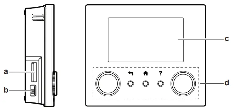
a Slot for the WLAN cartridge
b USB connector
c LCD screen
d Dials and buttons
Slot for WLAN cartridge
With the WLAN cartridge, the installer can connect the system to the internet. As a user, you can then control the system via the ONE CTA app. Note: This slot cannot be used for SD cards.
USB connector
With a USB memory stick, the installer can:
- Update the software. This requires a correct config file on the USB memory stick.
- Import the settings generated by E-Configurator (Heating Solutions Navigator) from the USB memory stick to the user interface (MMI). This requires a correct config file on the USB memory stick.
- Export the current settings (i.e. field settings, MMI EEPROM settings, schedule timers) from the user interface (MMI) to the USB memory stick.
LCD screen
The LCD screen has a sleeping function. After 15 min of noninteraction with the user interface, the screen darkens. Pressing any button or rotating any dial awakens the display. Dials and buttons
You use the dials and buttons:
- To navigate through the screens, menus, and settings of the LCD screen
- To set values
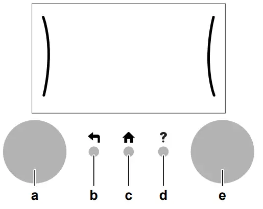
| Item | Description | |
| a | Left dial | The LCD shows an arc on the left side of the display when you can use the left dial. ▪ ▪ ▪ |
| b | Back button | |
| c | Home button | |
| d | Help button | |
| e | Right dial | The LCD shows an arc on the right side of the display when you can use the right dial. ▪ ▪ ▪ |
![]() INFORMATION
INFORMATION
Depending on the selected installer settings and unit type, settings will be visible/invisible.
![]() Setpoint screen
Setpoint screen
(*) Only applicable for models where cooling is possible
(**) Only accessible by installer
(***) Only applicable when WLAN is installed
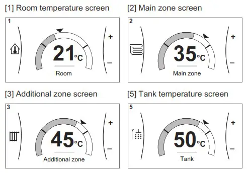
Possible screens: Overview
The most common screens are as follows:
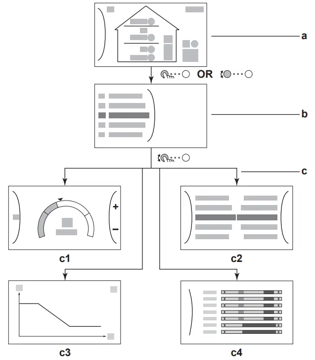
a Home screen
b Main menu screen
c Lower level screens:
c1: Setpoint screen
c2: Detailed screen with values
c3: Screen with weather-dependent curve
c4: Screen with schedule
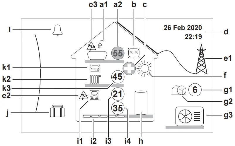
Home screen
Press the![]() button to go back to the home screen. You see an overview of the unit configuration and the room and setpoint temperatures. Only symbols applicable for your configuration are visible on the home screen
button to go back to the home screen. You see an overview of the unit configuration and the room and setpoint temperatures. Only symbols applicable for your configuration are visible on the home screen
| Possible actions on this screen | |
| Go through the list of the main menu. | |
| Go to the main menu screen. | |
| Enable/disable breadcrumbs. | |
| Item | Description | ||
| a | Domestic hot water | ||
| a1 |  | Domestic hot water | |
| a2 | Measured tank temperature(a) | ||
| Item | Description | ||
| b | Disinfection / Powerful | ||
| Disinfection mode active | |||
| Powerful operation mode active | |||
| c | Emergency | ||
| Heat pump failure and system operates in Emergency mode or heat pump is forced off. | |||
| d | Current date and time | ||
| e | Smart energy | ||
| e1 | Smart energy is available via solar panels or smart grid. | ||
| e2 |  | Smart energy is currently being used for space heating. | |
| e3 | | Smart energy is currently being used for domestic hot water. | |
| f | Space operation mode | ||
 | Cooling | ||
| Heating | |||
| g | Outdoor / quiet mode | ||
| g1 |  | Measured outdoor temperature(a) | |
| g2 | Quiet mode active | ||
| g3 | Outdoor unit | ||
| h | Domestic hot water tank | ||
 | Standalone tank installed | ||
| i | Main zone | ||
| i1 | Installed room thermostat type: | ||
 | Unit operation is decided based on the ambient temperature of the dedicated Human Comfort Interface (BRC1HHDA used as room thermostat). | ||
| Unit operation is decided by the external room thermostat (wired or wireless). | |||
| _ | No room thermostat was installed or set. Unit operation is decided based on the leaving water temperature regardless of the actual room temperature and/or heating demand of the room. | ||
| i2 | Installed heat emitter type: | ||
| Underfloor heating | |||
 | Fan coil unit | ||
 | Radiator | ||
| i3 |  | Measured room temperature(a) | |
| i4 |  | Leaving water temperature setpoint(a) | |
| j | Holiday mode | ||
 | Holiday mode active | ||
| Item | Description | ||
| k | Additional zone | ||
| k1 | Installed room thermostat type: | ||
| Unit operation is decided by the external room thermostat (wired or wireless). | |||
| — | No room thermostat was installed or set. Unit operation is decided based on the leaving water temperature regardless of the actual room temperature and/or heating demand of the room. | ||
| k2 | Installed heat emitter type: | ||
| Underfloor heating | |||
| Fan coil unit | ||
| Radiator | ||
| k3 |  | Leaving water temperature setpoint(a) | |
| l | Malfunction | ||
| A malfunction occurred. See “8.1 To display the help text in case of a malfunction” 4[ 18] for more information. | |||
(a) If the corresponding operation (for example space heating) is not active, the circle is greyed out.
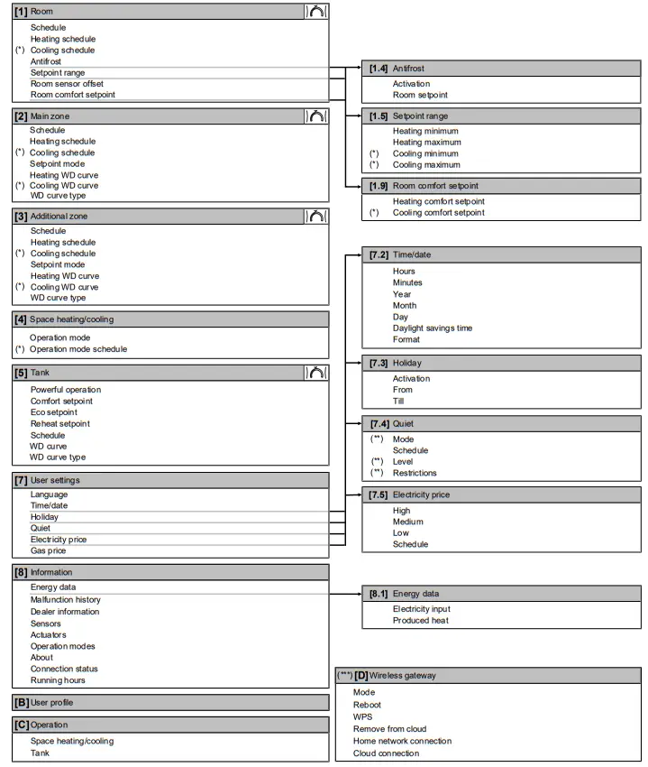
Main menu screen
Starting from the home screen, press (![]() ) or turn (
) or turn (![]() ) the left dial to open the main menu screen. From the main menu, you can access the different setpoint screens and submenus.
) the left dial to open the main menu screen. From the main menu, you can access the different setpoint screens and submenus.
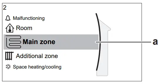
a Selected submenu
| Possible actions on this screen | |
| Go through the list. | |
| Enter the submenu. | |
| Enable/disable breadcrumbs. | |
| Submenu | Description | |
| [0] | Malfunctioning | Restriction: Only displayed if a malfunction occurs. See “8.1 To display the help text in case of a malfunction” [4 18] for more information. |
| [1] | Restriction: Only displayed if a dedicated Human Comfort Interface (BRC1HHDA used as room thermostat) is controlling the outdoor unit. Set the room temperature. | |
| [2] | Shows the applicable symbol for your main zone emitter type. Set the leaving water temperature for the main zone. | |
| [3] | Restriction: Only displayed if there are two leaving water temperature zones. Shows the applicable symbol for your additional zone emitter type. Set the leaving water temperature for the additional zone (if present). | |
| [4] | Shows the applicable symbol of your unit. Put the unit in heating mode or cooling mode. You cannot change the mode on heating only models. | |
| [5] | Set the domestic hot water tank temperature. | |
| [7] | Gives access to user settings such as holiday mode and quiet mode. | |
| [8] | Displays data and information about the outdoor unit. | |
| [9] | Restriction: Only for the installer. Gives access to advanced settings. | |
| [A] | Restriction: Only for the installer. Perform tests and maintenance. | |
| [B] | Change the active user profile. | |
| [C] | Turn heating/cooling functionality and domestic hot water preparation on or off. | |
| [D] | Restriction: Only displayed if a wireless LAN (WLAN) is installed. Contains settings needed when configuring the ONECTA app. |
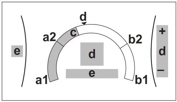
Setpoint screen
The setpoint screen is displayed for screens describing system components that need a setpoint value.
Examples
Explanation
| Possible actions on this screen | |
| Go through the list of the submenu. | |
| Go to the submenu. | |
| Adjust and automatically apply the desired temperature. | |
| Item | Description | |
| Minimum temperature limit | a1 | Fixed by the unit |
| a2 | Restricted by the installer | |
| Maximum temperature limit | b1 | Fixed by the unit |
| b2 | Restricted by the installer | |
| Current temperature | c | Measured by the unit |
| Desired temperature | d | Turn the right dial to increase/decrease. |
| Submenu | e | Turn or press the left dial to go to the submenu. |
Detailed screen with values
Example:
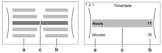
a Settings
b Values
c Selected setting and value
| Possible actions on this screen | |
| Go through the list of settings. | |
| Change the value. | |
| Go to the next setting. | |
| Confirm changes and proceed. | |
Turning operation ON or OFF
Visual indication
Certain functionalities of the unit can be enabled or disabled separately. If a functionality is disabled, the corresponding temperature icon in the home screen will be greyed out.
Space heating/cooling operation
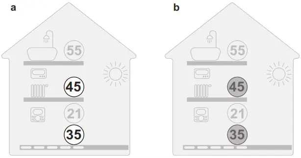
a Space heating/cooling operation ON
b Space heating/cooling operation OFF
Tank heating operation
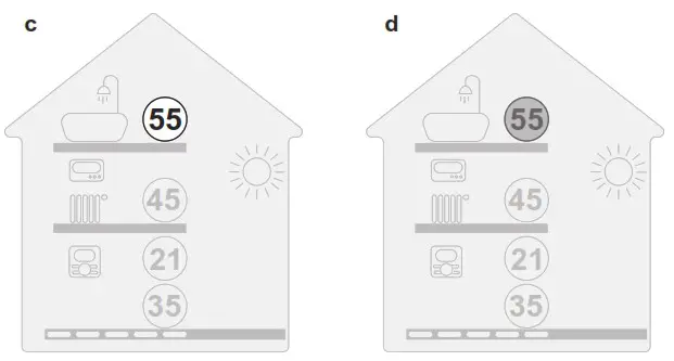
c Tank heating operation ON
d Tank heating operation OFF
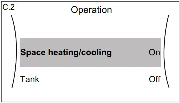
To turn ON or OFF
Space heating/cooling operation
![]() NOTICE
NOTICE
Room frost protection. Even if you turn OFF space heating/cooling operation ([C.2]: Operation > Space heating/cooling), room frost protection operation –if enabled– can still activate. However, for leaving water temperature control and external room thermostat control, the protection is NOT guaranteed.
![]() NOTICE
NOTICE
Water pipe freeze prevention. Even if you turn OFF space heating/cooling operation ([C.2]: Operation > Space heating/cooling), water pipe freeze prevention – if enabled– will remain active.
| 1 | Go to [C.2]: Operation > Space heating/cooling.
| |
| 2 | Set operation to On or Off. |
Tank heating operation![]() NOTICE
NOTICE
Disinfection mode. Even if you turn OFF tank heating operation ([C.3]: Operation > Tank), disinfection mode will remain active. However, if you turn it OFF while disinfection is running, an AH error occurs.
| 1 | Go to [C.3]: Operation > Tank.
| |
| 2 | Set operation to On or Off. |
Reading out information
To read out information
| 1 | Go to [8]: Information. |
Possible read-out information
| In menu… | You can read out… |
| [8.1] Energy data | Produced energy, consumed electricity, and consumed gas |
| [8.2] Malfunction history | Malfunction history |
| [8.3] Dealer information | Contact/helpdesk number |
| [8.4] Sensors | Room temperature, outside temperature, leaving water temperature,… |
| [8.5] Actuators | Status/mode of each actuator Example: Unit pump ON/OFF |
| [8.6] Operation modes | Current operation mode Example: Defrost/oil return mode |
| [8.7] About | Version information about the system |
| [8.8] Connection status | Information about the connection status of the unit, the room thermostat and WLAN. |
| [8.9] Running hours | Running hours of specific system components |
Space heating/cooling control
Setting the space operation mode
About space operation modes
Your unit can be a heating or a heating/cooling model:
- If your unit is a heating model, it can heat up a space.
- If your unit is a heating/cooling model, it can both heat up and cool down a space. You have to tell the system which operation mode to use.
To tell the system which space operation to use, you can:
| You can… | Location |
| Check which space operation mode is currently used. | Home screen |
| Set the space operation mode permanently. | Main menu |
| Restrict automatic changeover according to a monthly schedule. |
To set the space operation mode
| 1 | Go to [4.1]: Space heating/cooling > Operation mode | |
| 2 | Select one of the following options: ▪ Heating: Only heating mode ▪ Cooling: Only cooling mode ▪ Automatic: The operation mode changes automatically between heating and cooling based on the outdoor temperature. Restricted per month according to the Operation mode schedule [4.2]. |
To restrict automatic changeover according to a schedule
Conditions: You set the space operation mode to Automatic.
| 1 | Go to [4.2]: Space heating/cooling > Operation mode schedule. | |
| 2 | Select a month. | |
| 3 | For each month, select an option: ▪ Reversible: Not restricted ▪ Heating only: Restricted ▪ Cooling only: Restricted | |
| 4 | Confirm the changes. |
To change the desired room temperature
During room temperature control, you can use the room temperature setpoint screen to read out and adjust the desired room temperature.
| 1 | Go to [1]: Room.
| |
| 2 | Adjust the desired room temperature.
|
If scheduling is on after changing the desired room temperature
- The temperature will stay the same as long as there is no scheduled action.
- The desired room temperature will return to its scheduled value whenever a scheduled action occurs.
You can avoid scheduled behaviour by (temporarily) turning off scheduling.
To turn off room temperature scheduling
| 1 | Go to [1.1]: Room > Schedule. | |
| 2 | Select No. |
To change the desired leaving water temperature
![]() INFORMATION
INFORMATION
The leaving water is the water that is sent to the heat emitters. The desired leaving water temperature is set by your installer in accordance with the heat emitter type. Only adjust the leaving water temperature settings in case of problems.
You can use the leaving water temperature setpoint screen to read out and adjust the desired leaving water temperature.
| 1 | Go to [2]: Main zone or [3]: Additional zone.
| |
| 2 | Adjust the desired leaving water temperature.
|
Domestic hot water control
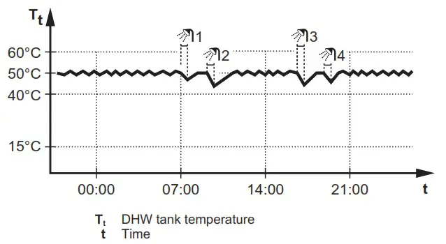
Reheat mode
In reheat mode, the DHW tank continuously heats up to the temperature shown on the home screen (example: 50°C) when the temperature drops below a certain value.
![]() INFORMATION
INFORMATION
Risk of space heating capacity shortage for domestic hot water tank without internal booster heater: In case of frequent domestic hot water operation, frequent and long space heating/cooling interruption will happen when selecting the following:
Tank > Heat up mode > Reheat only.
![]() INFORMATION
INFORMATION
When the DHW tank mode is reheat, the risk for capacity shortage and comfort problem is significant. In case of frequent reheat operation, space heating/cooling function is regularly interrupted.
Scheduled mode
In scheduled mode, the DHW tank produces hot water corresponding to a schedule. The best time to allow the tank to produce hot water is at night, because the space heating demand is lower.
Example:
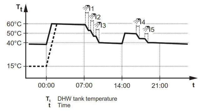
- Initially, the DHW tank temperature is the same as the temperature of the domestic water entering the DHW tank (example: 15°C).
- At 00:00 the DHW tank is programmed to heat up the water to a preset value (example: Comfort = 60°C).
- During the morning, you consume hot water and the DHW tank temperature decreases.
- At 14:00 the DHW tank is programmed to heat up the water to a preset value (example: Eco = 50°C). Hot water is available again.
- During the afternoon and evening, you consume hot water again and the DHW tank temperature decreases again.
- At 00:00 the next day, the cycle repeats.
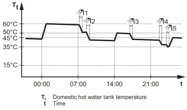
Scheduled + reheat mode
In scheduled + reheat mode, the domestic hot water control is the same as in scheduled mode. However, when the DHW tank temperature drops below a preset value (=reheat tank temperature – hysteresis value; example: 35°C), the DHW tank heats up until it reaches the reheat set point (example: 45°C). This ensures that a minimum amount of hot water is available at all times.
Example:
Using DHW powerful operation
About powerful operation
Powerful operation allows the domestic hot water to be heated by the backup heater or booster heater. Use this mode on days when there is more hot water usage than usual.
To check if powerful operation is active
If ![]() is displayed on the home screen, powerful operation is active.
is displayed on the home screen, powerful operation is active.
Activate or deactivate Powerful operation as follows:
| 1 | Go to [5.1]: Tank > Powerful operation | |
| 2 | Turn powerful operation Off or On. |
Usage example: You immediately need more hot water
You are in the following situation:
- You already consumed most of your domestic hot water.
- You cannot wait for the next scheduled action to heat up the domestic hot water tank.
Then you can activate powerful operation. The domestic hot water tank will start heating up the water to the Comfort temperature.
![]() INFORMATION
INFORMATION
When powerful operation is active, the risk of space heating/cooling and capacity shortage comfort problems is significant. In case of frequent omestic hot water operation, frequent and long space heating/cooling interruptions will happen.
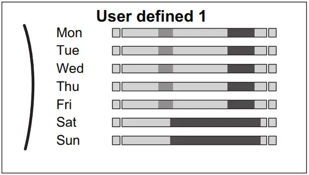
Schedule screen: Example
This example shows how to set a room temperature schedule in heating mode for the main zone.
![]() INFORMATION
INFORMATION
The procedures to program other schedules are similar.
To program the schedule: overview
Example: You want to program the following schedule:
Prerequisite: The room temperature schedule is only available if room thermostat control is active. If leaving water temperature control is active, you can program the main zone schedule instead.
- Go to the schedule.
- (optional) Clear the content of the whole week schedule or the content of a selected day schedule.
- Program the schedule for Monday.
- Copy the schedule to the other weekdays.
- Program the schedule for Saturday and copy it to Sunday.
- Give the schedule a name.
To go to the schedule
| 1 | Go to [1.1]: Room > Schedule. | |
| 2 | Set scheduling to Yes. | |
| 3 | Go to [1.2]: Room > Heating schedule. |
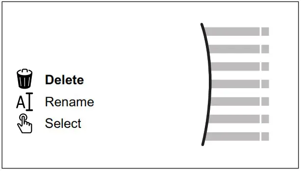
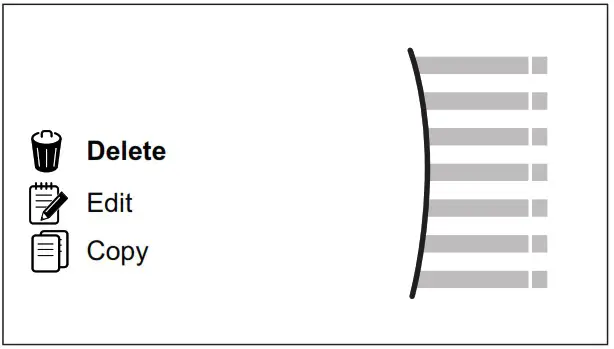
To clear the content of the week schedule
| 1 | Select the name of the current schedule.
| |
| 2 | Select Delete.
| |
| 3 | Select OK to confirm. |
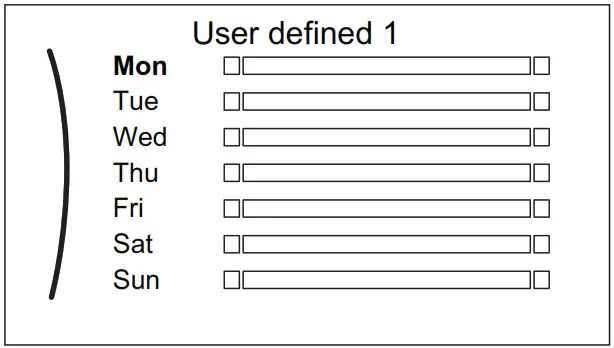
To clear the content of a day schedule
| 1 | Select the day of which you want to clear the content. For example Friday
| |
| 2 | Select Delete.
| |
| 3 | Select OK to confirm. |
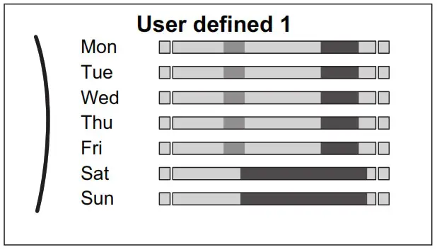
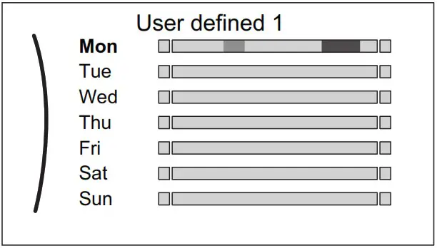
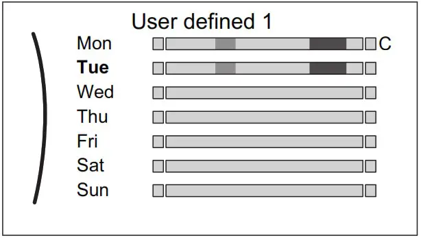
To program the schedule for Monday
| 1 | Select Monday.
| |
| 2 | Select Edit.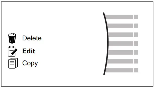 | |
| 3 | Use the left dial to select an entry and edit the entry with the right dial. You can program up to 6 actions each day. On the bar, a high temperature has a darker colour than a low temperature.
|
|
| 4 | Confirm the changes. Result: The schedule for Monday is defined. The value of the last action is valid until the next programmed action. In this example, Monday is the first day you programmed. Thus, the last programmed action is valid up to the first action of next Monday. |
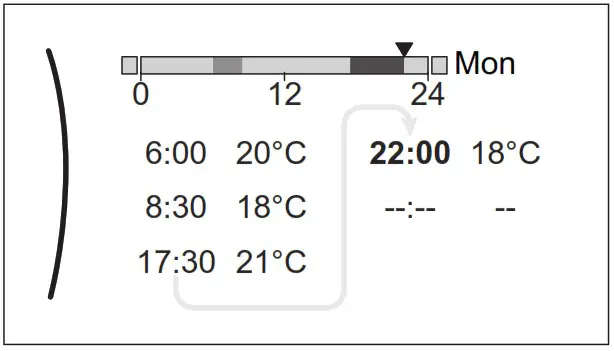 Note: To clear an action, set its time as the time of the previous action.
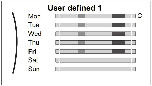
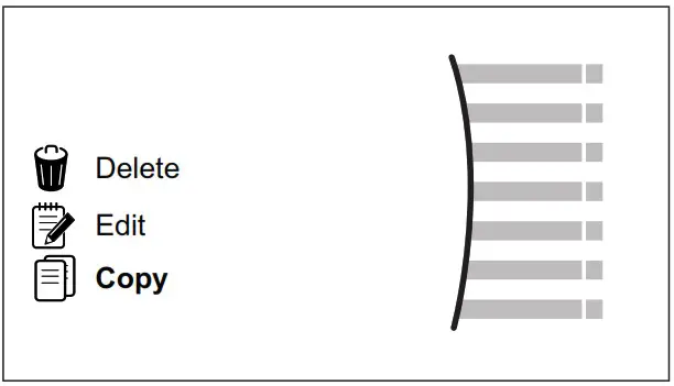
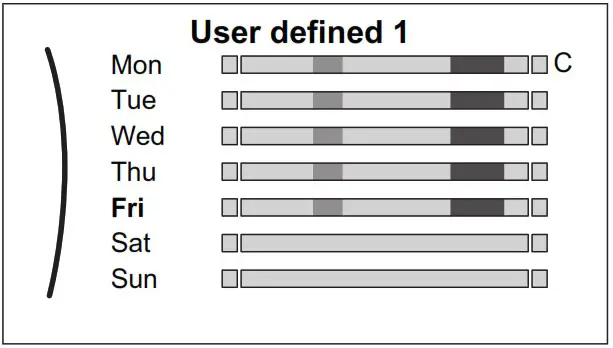
To copy the schedule to the other weekdays
| 1 | Select Monday.
| |
| 2 | Select Copy.
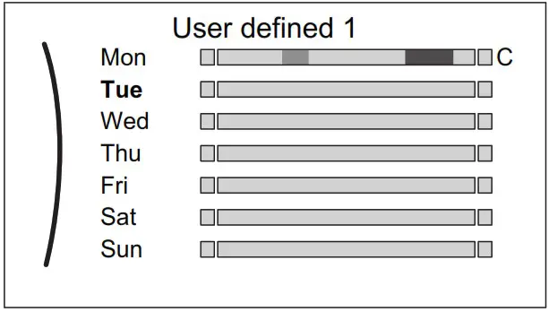
Result: Next to the copied day, “C” is displayed. | |
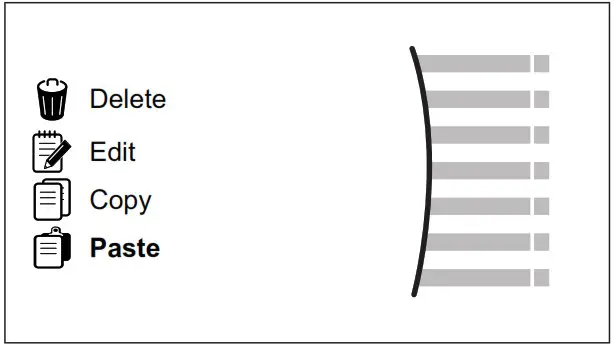
| 3 | Select Tuesday.
| |
| 4 | Select Paste.
Result:
| |
| 5 | Repeat this action for all other weekdays.
| _ |
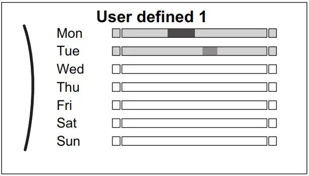
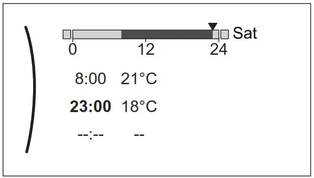
To program the schedule for Saturday and copy it to Sunday
| 1 | Select Saturday. | |
| 2 | Select Edit. | |
| 3 | Use the left dial to select an entry and edit the entry with the right dial.
| |
| 4 | Confirm the changes. | |
| 5 | Select Saturday. | |
| 6 | Select Copy. | |
| 7 | Select Sunday. |
| 8 | Select Paste. Result: 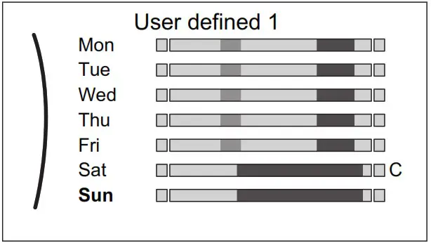 |
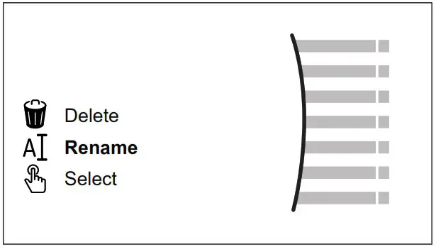
To rename the schedule
| 1 | Select the name of the current schedule.
| |
| 2 | Select Rename.
| |
| 3 | (optional) To delete the current schedule name, browse through the character list until ← is displayed, then press to remove the previous character. Repeat for each character of the schedule name. | |
| 4 | To name the current schedule, browse through the character list and confirm the selected character. The schedule name can contain up to 15 characters. | |
| 5 | Confirm the new name. |
![]() INFORMATION
INFORMATION
Not all schedules can be renamed.
Weather-dependent curve
What is a weather-dependent curve?
Weather-dependent operation
The unit operates ‘weather dependent’ if the desired leaving water or tank temperature is determined automatically by the outdoor temperature. It therefore is connected to a temperature sensor on the North wall of the building. If the outdoor temperature drops or rises, the unit compensates instantly. Thus, the unit does not have to wait for feedback by the thermostat to increase or decrease the temperature of the leaving water or tank. Because it reacts more quickly, it prevents high rises and drops of the indoor temperature and water temperature at tap points.
Advantage
Weather-dependent operation reduces energy consumption.
Weather-dependent curve
To be able to compensate for differences in temperature, the unit relies on its weather-dependent curve. This curve defines how much the temperature of the tank or leaving water must be at different outdoor temperatures. Because the slope of the curve depends on local circumstances such as climate and the insulation of the building, the curve can be adjusted by an installer or user.
Types of weather-dependent curve
There are 2 types of weather-dependent curves:
- 2-points curve
- Slope-offset curve
Which type of curve you use to make adjustments, depends on your personal preference. See “5.9.4 Using weather-dependent curves” [4 17].
Availability
The weather-dependent curve is available for:
- Main zone – Heating
- Main zone – Cooling
- Additional zone – Heating
- Additional zone – Cooling
- Tank (only available to installers)
INFORMATION
To operate weather dependent, correctly configure the setpoint of the main zone, additional zone or tank. See “5.9.4 Using weather-dependent curves” [4 17].
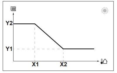
2-points curve
Define the weather-dependent curve with these two setpoints:
- Setpoint (X1, Y2)
- Setpoint (X2, Y1)
Example
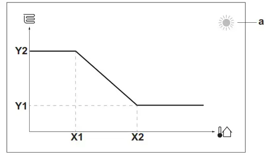
| Item | Description |
| a | Selected weather-dependent zone: ▪ ▪ ▪ |
| X1, X2 | Examples of outdoor ambient temperature |
| Y1, Y2 | Examples of desired tank temperature or leaving water temperature. The icon corresponds to the heat emitter for that zone: ▪ ▪ ▪ ▪ |
| Possible actions on this screen | |
| Go through the temperatures. | |
| Change the temperature. | |
| Go to the next temperature. | |
| Confirm changes and proceed. | |
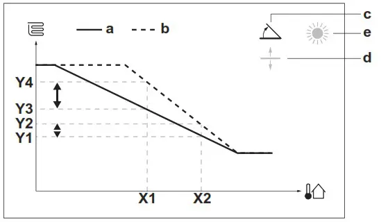
Slope-offset curve
Slope and offset
Define the weather-dependent curve by its slope and offset:
- Change the slope to differently increase or decrease the temperature of the leaving water for different ambient temperatures. For example, if leaving water temperature is in general fine but at low ambient temperatures too cold, raise the slope so that leaving water temperature is heated increasingly more at decreasingly lower ambient temperatures.
- Change the offset to equally increase or decrease the temperature of the leaving water for different ambient temperatures. For example, if leaving water temperature is always a bit too cold at different ambient temperatures, shift the offset up to equally increase the leaving water temperature for all ambient temperatures.
Examples
Weather-dependent curve when slope is selected:
Weather-dependent curve when offset is selected:
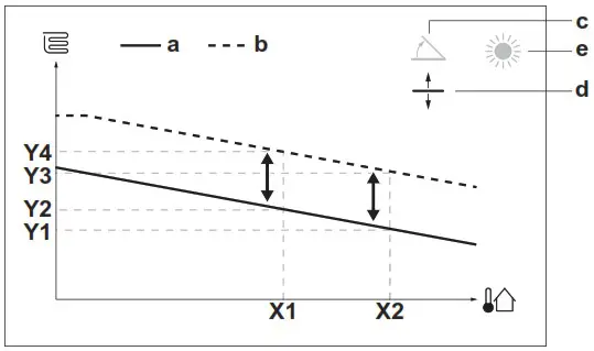
| Item | Description |
| a | WD curve before changes. |
| b | WD curve after changes (as an example): ▪ When the slope is changed, the new preferred temperature at X1 is unequally higher than the preferred temperature at X2. ▪ When the offset is changed, the new preferred temperature at X1 is equally higher as the preferred temperature at X2. |
| c | Slope |
| d | Offset |
| e | Selected weather-dependent zone: ▪ ▪ ▪ |
| X1, X2 | Examples of outdoor ambient temperature |
| Y1, Y2, Y3, Y4 | Examples of desired tank temperature or leaving water temperature. The icon corresponds to the heat emitter for that zone: ▪ ▪ ▪ ▪ |
| Possible actions on this screen | |
| Select slope or offset. | |
| Increase or decrease the slope/offset. | |
| When the slope is selected: set slope and go to offset. When the offset is selected: set offset. | |
| Confirm changes and return to the submenu. |
Using weather-dependent curves
Configure weather-dependent curves as follows:
To define the setpoint mode
To use the weather-dependent curve, you need to define the correct setpoint mode:
| Go to setpoint mode … | Set the setpoint mode to … |
| Main zone — Heating | |
| [2.4] Main zone > Setpoint mode | WD heating, fixed cooling OR Weather dependent |
| Main zone – Cooling | |
| [2.4] Main zone > Setpoint mode | Weather dependent |
| Additional zone – Heating | |
| [3.4] Additional zone > Setpoint mode | WD heating, fixed cooling, OR Weather dependent |
| Additional zone – Cooling | |
| [3.4] Additional zone > Setpoint mode | Weather dependent |
| Tank | |
| [5.B] Tank > Setpoint mode | Restriction: Only available to installers. Weather dependent |
To change the type of weather-dependent curve
To change the type for all zones (main + additional) and for the tank, go to [2. E] the Main zone > WD curve type.
Viewing which type is selected is also possible via:
- [3.C] Additional zone > WD curve type
- [5. E] Tank > WD curve type
Restriction: Only available to installers.
To change the weather-dependent curve
| Zone | Go to … |
| Main zone – Heating | [2.5] Main zone > Heating WD curve |
| Main zone – Cooling | [2.6] Main zone > Cooling WD curve |
| Additional zone – Heating | [3.5] Additional zone > Heating WD curve |
| Additional zone – Cooling | [3.6] Additional zone > Cooling WD curve |
| Tank | Restriction: Only available to installers. [5. C] Tank > WD curve |
![]() INFORMATION
INFORMATION
Maximum and minimum setpoints
You cannot configure the curve with temperatures that are higher or lower than the set maximum and minimum setpoints for that zone or for the tank. When the maximum or minimum setpoint is reached, the curve flattens out.
To fine-tune the weather-dependent curve: the slope-offset curve
The following table describes how to fine-tune the weather-dependent curve of a zone or tank:
| You feel … | Fine-tune with slope and offset: | ||
| At regular outdoor temperatures … | At cold outdoor temperatures … | Slope | Offset |
| OK | Cold | ↑ | — |
| OK | Hot | ↓ | — |
| Cold | OK | ↓ | ↑ |
| Cold | Cold | — | ↑ |
| Cold | Hot | ↓ | ↑ |
| Hot | OK | ↑ | ↓ |
| Hot | Cold | ↑ | ↓ |
| Hot | Hot | — | ↓ |
To fine-tune the weather-dependent curve: the 2-points curve
The following table describes how to fine-tune the weather-dependent curve of a zone or tank:
| You feel … | Fine-tune with setpoints: | ||||
| At regular outdoor temperatures … | At cold outdoor temperatures … | Y2(a) | Y1(a) | X1(a) | X2(a) |
| OK | Cold | ↑ | — | ↑ | — |
| OK | Hot | ↓ | — | ↓ | — |
| Cold | OK | — | ↑ | — | ↑ |
| Cold | Cold | ↑ | ↑ | ↑ | ↑ |
| Cold | Hot | ↓ | ↑ | ↓ | ↑ |
| Hot | OK | — | ↓ | — | ↓ |
| Hot | Cold | ↑ | ↓ | ↑ | ↓ |
| Hot | Hot | ↓ | ↓ | ↓ | ↓ |
(a) See “5.9.2 2-points curve” [4 16].
Energy saving tips
Tips about room temperature
- Make sure the desired room temperature is NEVER too high (in heating mode) or too low (in cooling mode), but ALWAYS according to your actual needs. Each saved degree can save up to 6% of heating/cooling costs.
- Do NOT increase/decrease the desired room temperature to speed up space heating/cooling. The space will NOT heat up/cool down faster.
- When your system layout contains slow heat emitters (example: underfloor heating), avoid large fluctuations of the desired room temperature and do NOT let the room temperature drop too low/ rise too high. It will take more time and energy to heat up/cool down the room again.
- Use a weekly schedule for your normal space heating or cooling needs. If necessary, you can easily deviate from the schedule:
- For shorter periods: You can overrule the scheduled room temperature until the next scheduled action.
Example: When you have a party, or when you are leaving for a couple of hours. - For longer periods: You can use the holiday mode.
Tips about DHW tank temperature
- Use a weekly schedule for your normal domestic hot water needs (ONLY in scheduled mode).
- Program to heat up the DHW tank to a preset value (Comfort = higher DHW tank temperature) during the night because then space heating demand is lower.
- If heating up the DHW tank once at night is NOT sufficient, a program to additionally heat up the DHW tank to a preset value (Eco = lower DHW tank temperature) during the day.
- Make sure the desired DHW tank temperature is NOT too high. Example: After installation, lower the DHW tank temperature daily by 1°C and check if you still have enough hot water.
- Program to turn ON the domestic hot water pump ONLY during periods of the day when instant hot water is necessary.
Example: In the morning and evening.
Maintenance and service
Overview: Maintenance and service
The installer has to perform yearly maintenance. You can find the contact/helpdesk number via the user interface.
| 1 | Go to [8.3]: Information > Dealer information. |
As an end user, you have to:
- Keep the area around the unit clean.
- Keep the user interface cleanly with a soft damp cloth. Do NOT use any detergents.
- Regularly check if the water pressure is above 1 bar.
Refrigerant
This product contains fluorinated greenhouse gases. Do NOT vent gases into the atmosphere.
Refrigerant type: R32 Global warming potential (GWP) value: 675
NOTICE
Applicable legislation on fluorinated greenhouse gases requires that the refrigerant charge of the unit is indicated both in weight and CO2 equivalent.
Formula to calculate the quantity in CO2 equivalent tonnes: GWP value of the refrigerant × total refrigerant charge [in kg] / 1000
Please contact your installer for more information.
 WARNING: MILDLY FLAMMABLE MATERIAL
The refrigerant inside this unit is mildly flammable.
 WARNING
The appliance shall be stored so as to prevent mechanical damage and in a well-ventilated room without continuously operating ignition sources (example: open flames, an operating gas appliance, or an operating electric heater).
WARNING
- Do NOT pierce or burn refrigerant cycle parts.
- Do NOT use cleaning materials or means to accelerate the defrosting process other than those recommended by the manufacturer.
- Be aware that the refrigerant inside the system is odorless.
WARNING
- The refrigerant inside the unit is mildly flammable but normally does NOT leak. If the refrigerant leaks in the room and comes in contact with fire from a burner, a heater, or a cooker, this may result in fire or the formation of harmful gas.
- Turn OFF any combustible heating devices, ventilate the room, and contact the dealer where you purchased the unit.
- Do NOT use the unit until a service person confirms that the part from which the refrigerant leaked has been repaired.
Troubleshooting
Contact
For the symptoms listed below, you can try to solve the problem yourself. For any other problem, contact your installer. You can find the contact/helpdesk number via the user interface.
| 1 | Go to [8.3]: Information > Dealer information. |
To display the help text in case of a malfunction
In case of a malfunction, the following will appear on the home screen depending on the severity:
 : Error
 : Malfunction
You can get a short and a long description of the malfunction as follows:
| 1 | Press the left dial to open the main menu and go to Malfunctioning. Result: A short description of the error and the error code are displayed on the screen. | |
| 2 | Press ? in the error screen. Result: A long description of the error is displayed on the screen. | ? |
To check the malfunction history
Conditions: The user permission level is set to the advanced end user.
| 1 | Go to [8.2]: Information > Malfunction history. |
You see a list of the most recent malfunctions.
Symptom: You are feeling too cold (hot) in your living room
| Possible cause | Corrective action |
| The desired room temperature is too low (high). | Increase (decrease) the desired room temperature. See “5.6.2 To change the desired room temperature” [4 12]. If the problem recurs daily, do one of the following: ▪ Increase (decrease) the room temperature preset value. See the user reference guide. ▪ Adjust the room temperature schedule. See “5.8 Schedule screen: Example” [4 14]. |
| The desired room temperature cannot be reached. | Increase the desired leaving water temperature in accordance with the heat emitter type. See “5.6.3 To change the desired leaving water temperature” [4 12]. |
| The weather-dependent curve is set incorrectly. | Adjust the weather-dependent curve. See “5.9 Weather dependent curve” [4 15]. |
Symptom: The water at the tap is too cold
| Possible cause | Corrective action |
| You ran out of domestic hot water because of unusually high consumption. | If you immediately need domestic hot water, activate the DHW tank Powerful operation. However, this consumes extra energy. See “5.7.4 Using DHW powerful operation” [4 13]. If the problems recur daily, do one of the following: ▪ Increase the DHW tank temperature preset value. See the user reference guide. ▪ Adjust the DHW tank temperature schedule. Example: Program to additionally heat up the DHW tank to a preset value (Eco setpoint = lower tank temperature) during the day. See “5.8 Schedule screen: Example” [4 14]. |
| The desired DHW tank temperature is too low. |
Symptom: Heat pump failure
When the heat pump fails to operate, the backup heater (if available) and/or booster heater (if available) can serve as an emergency heater. It then takes over the heat load either automatically or by manual interaction.
- When Emergency is set to Automatic and a heat pump failure occurs, the backup heater automatically takes over the heat load, and the booster heater in the optional tank takes over the domestic hot water production.
- When Emergency is set to Manual and a heat pump failure occurs, the domestic hot water heating and space heating stop.
To manually recover it via the user interface, go to the Malfunctioning main menu screen and confirm whether the backup heater and/or booster heater can take over the heat load or not. - Alternatively, when Emergency is set to:
- auto SH reduced/DHW on, space heating is reduced but domestic hot water is still available.
- auto SH reduced/DHW off, space heating is reduced and domestic hot water is NOT available.
- auto SH normal/DHW off, space heating operates as normally but domestic hot water is NOT available.
Similarly, as in Manual mode, the unit can take the full load with the backup heater and/or booster heater if the user activates this via the malfunctioning main menu screen.
When the heat pump fails, ![]() or
or ![]() will appear on the user interface.
will appear on the user interface.
| Possible cause | Corrective action |
| Heat pump is damaged. | See “8.1 To display the help text in case of a malfunction” [4 18]. |
![]() INFORMATION
INFORMATION
When the backup heater or booster heater takes over the heat load, electricity consumption will be considerably higher.
Symptom: The system is making gurgling noises after commissioning
| Possible cause | Corrective action |
| There is air in the system. | Purge air from the system. (a) |
| Incorrect hydraulic balance. | To be performed by the installer: 1 Perform hydraulic balancing to assure that the flow is correctly distributed between the emitters. 2 If hydraulic balancing is not sufficient, change the pump limitation settings ([9-0D] and [9-0E] if applicable). |
| Various malfunctions. | Check if |
(a) We recommend purging air with the air purge function of the unit (to be performed by the installer). If you purge air from the heat emitters or collectors, mind the following:
WARNING
Air purging heat emitters or collectors. Before you purge air from heat emitters or collectors, check if ![]() or
or ![]() is displayed on the home screen of the user interface.
is displayed on the home screen of the user interface.
- If not, you can purge the air immediately.
- If yes, make sure that the room where you want to purge air is sufficiently ventilated. Reason: Refrigerant might leak into the water circuit, and subsequently into the room when you purge air from the heat emitters or collectors.
Disposal
![]() NOTICE
NOTICE
Do NOT try to dismantle the system yourself: the dismantling of the system, treatment of the refrigerant, oil, and other parts MUST comply with applicable legislation. Units MUST be treated at a specialized treatment facility for reuse, recycling, and recovery.
Glossary
DHW = Domestic hot water
Hot water is used, in any type of building, for domestic purposes.
LWT = Leaving water temperature
Water temperature at the water outlet of the unit.
Installer settings: Tables to be filled in by the installer
Configuration wizard
| Setting I | Fill in… | |
| System | ||
| Indoor unit type (read-only) | ||
| Backup heater type [9.3.1] | ||
| Domestic hot water [9.2.1] | ||
| Emergency [9.5] | ||
| Number of zones [4.4] | ||
| Glycol Filled system (overview field setting [E-OD]) | ||
| Booster heater capacity [9.4.1] (if applicable) | ||
| Bivalent [9. C] | ||
| Backup heater | ||
| Voltage [9.3.2] | ||
| Configuration [9.3.3] | ||
| Capacity step 1 [9.3.4] | ||
| Additional capacity step 2 [9.3.5] (if applicable) | ||
| Main zone | ||
| Emitter type [2.7] | ||
| Control [2.9] | ||
| Setpoint mode [2.4] | ||
| Schedule [2.1] | ||
| WD curve type [2. E] | ||
| Additional zone (only if [4.4]=1, dual zone) | ||
| Emitter type [3.7] | ||
| Control (read-only) [3.9] | ||
| Setpoint mode [3.4] | ||
| Schedule [3.1] | ||
| WD curve type [3. C] (read-only) | ||
| Tank (if applicable) | ||
| Heat up mode [5.6] | ||
| Comfort setpoint [5.2] | ||
| Eco setpoint [5.3] | ||
| Reheat setpoint [5.4] | ||
| Setpoint mode [5. B] | ||
| WD curve type [5. E] (read-only) | ||
| Setting | Fill in… | |
| Main zone | ||
| Ext thermostat type [2A] | ||
| Additional zone (if applicable) | ||
| Ext thermostat type [3.A] | ||
| Information | ||
| Dealer information [8.3] | ||
![]()
EBLA04~08E2V3+E23V3 + EDLA04~08E2V3+E23V3
Daikin Altherma 3 M 4P685230-1 – 2022.04
![]()

DAIKIN EUROPE N.V.
Zandvoordestraat 300,B-8400 Oostende, Belgium
Copyright 2022 Daikin
4P685230-1 2022.04


