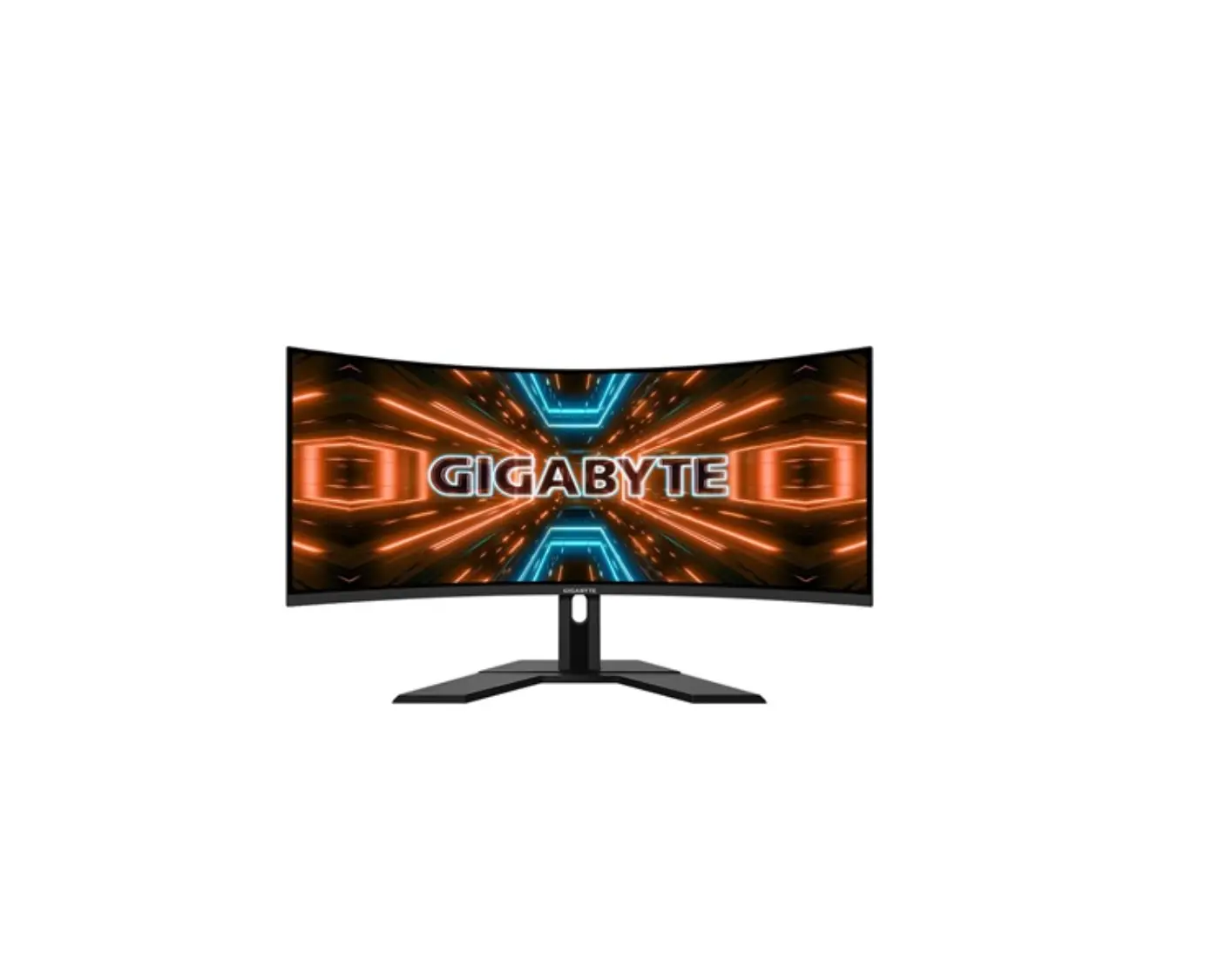
SUZOHAPP 1500R J-Curved LCD Monitor
General Description
Overview
- SUZOHAPP 1500R J-Curved LCD Monitor INF-5503UHJLIPC-U is a high performance. TFT LCD monitor providing a high quality screen image.
- This monitor supports HDMI and DP input. Other input options are available.
- Wide input resolution range up to UHD (3840 x 2160@60Hz).
- It is designed for industrial use with Auto power on, up scaling performance adequate for low-resolution applications and enhanced design margin for reliability.
- It is available in matching touch and non-touch designs.
General Specifications
| LCD Panel | Size | 55.0” Diagonal | ||
| Active Display Area | 680.4mm(H) x 1193.35mm(V) | |||
| Type No. | IC-550JAT1-500 (With Touchscreen) | |||
| Number of Pixels | 2160 (H) x 3840 (V) | |||
| Pixel Arrangement | RGB Vertical Stripe | |||
| Pixel Pitch | 0.315mm(H) x 0.315mm(V) | |||
| Color Depth | 8bit+FRC / 1.07B True Colors | |||
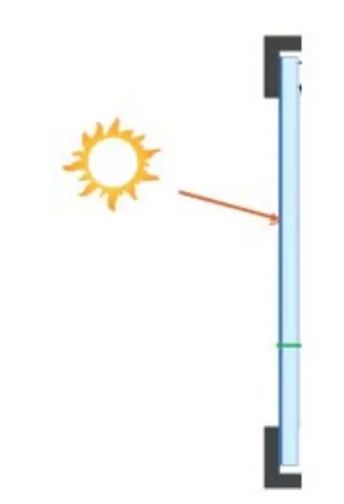
| Surface Treatments | Anti-Glare Haze 25%, Hard –coating (3H) | |||
| Viewing Angle (CR>10) | R/L: 178 degree (89/89) U/D: 178 degree (89/89) | |||
| Contrast Ratio | Typ. 4000 : 1 | |||
| Response Time(Typ.) | 8ms | |||
| Average Brightness | Typ. 500 cd/m2 (With Touchscreen) | |||
| Frame Rate | Typ. 60Hz | |||
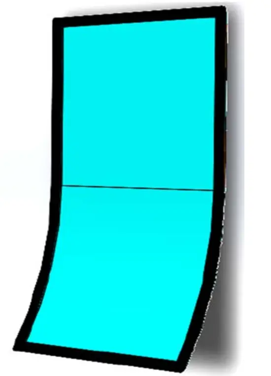
| Curved Type | J-Type | |||
| Radius | 1500R | |||
| Backlight Unit | LED | |||
| Input Resolution | Prime | 3840 x 2160@60Hz | ||
| Standard | 800×600@60/72/75Hz, 1024×768@60/70/75Hz, 1280×1024@60/75Hz, 1366×768@60Hz, 1600×900@60Hz, 1680×1050@60Hz, 1920×1080@60Hz, 1920×1200@60Hz 2560x 1600@60Hz, 3840×2160@60Hz | |||
| Input Signal Port | HDMI 2.0 | 19pin HDMI Jack x 2 Port | ||
| DP(Display Port) 1.2 | 15pin DP Jack x 2 Port | |||
| Power Jack | Power Mini-Din 4P x 1 Port | |||
| Scanning Frequency | Horizontal | 30 ~130Khz | ||
| Vertical | 55 ~75Hz | |||
| OSD Control | Menu, Select, Up, Down, Power | |||
| Plug & Play | VESA DDC 2B Ver1.3 | |||
| Touchscreen | Touch Panel | P-CAP Touch : 55.0” J-Curved Touch / 10 Point (TP550FI4C-AJ) | ||
| Controller | BTC-B1 (Touch IC : Weida) | |||
| Controller Interface | USB 2.0 Type “B” | |||
| RoHS | RoHS2 Compliance | |||
| Mounting Options | 400(H) x 400(V)mm M6 VESA Mounting Holes | |||
 Application Caution Application Caution | ||||
| ||||
Environmental and Reliability Specification
- This specification depends on the LCD panel characteristics. Please refer to the manufacturer’s panel specification for details.
| Item | Symbol | Min | Max | Unit |
| Operating Temperature | TOP | 0 | +50 | °C |
| Operating Humidity | HOP | 10 | 90 | % |
| Storage Temperature | TST | -20 | +60 | °C |
| Storage Humidity | HST | 10 | 90 | % |
Power Supply Rating
| Optional PSU Input Voltage | AC 100 ~ 240VAC,50/60Hz |
| Optional PSU Output Voltage | DC 24V8.33A |
| Monitor DC Input Voltage | 24VDC |
| Power Consumption | Typ. 140W (24VDC / 5.8A) |
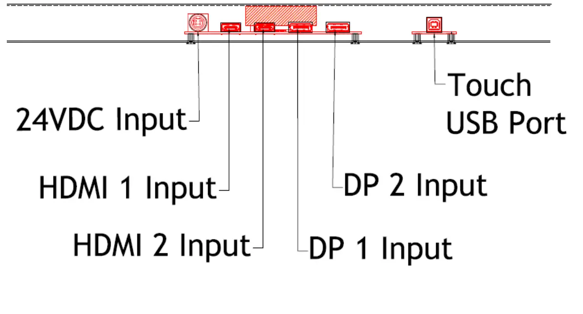
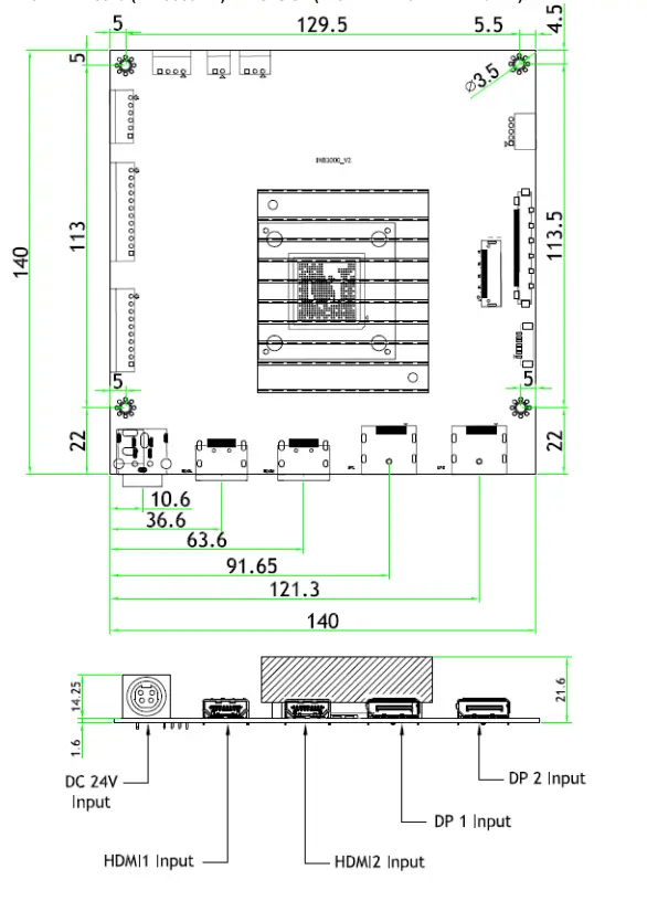
Input/Output Port
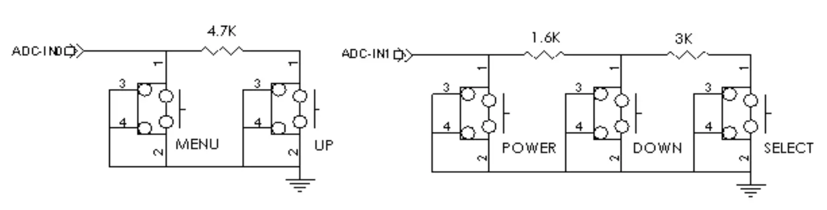
User Control & OSD
Key Control Board
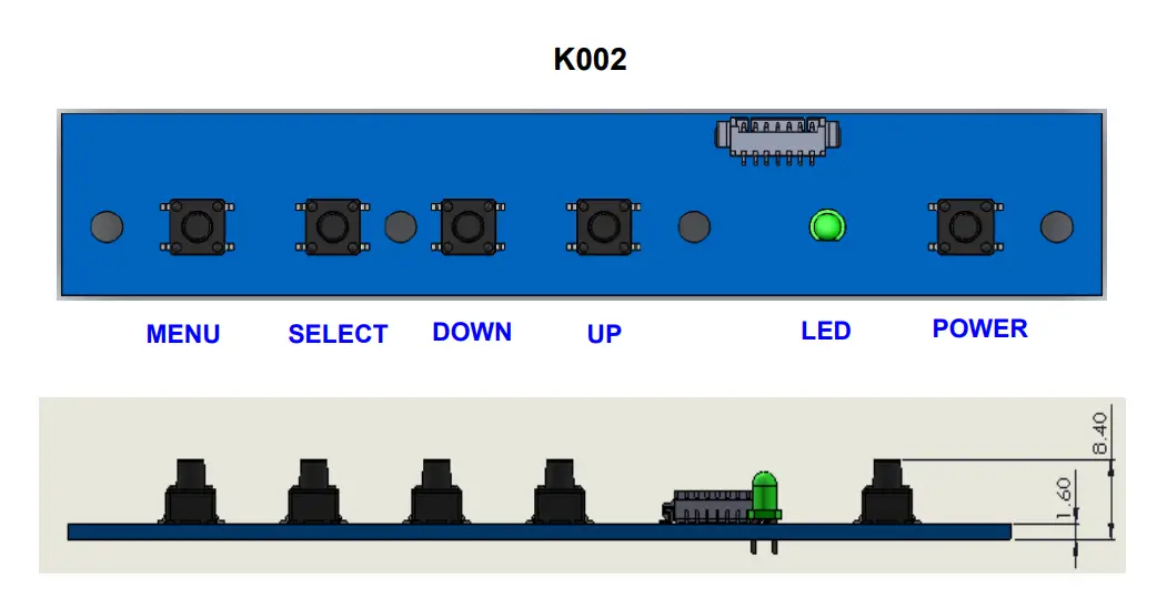
| Button | Function | Status | HOT Key |
| LED | Indicates operation status | Green : Normal State Red : Off Mode Green Blinking : DPMS Mode | |
| POWER | Power on/off | ||
| MENU | Enable MENU Window Disable MENU Window Exit from Sub function | ||
| SELECT | Select function | No OSD Window, Input Source Change | |
| DOWN | Move to Down or Left | No OSD Window, Auto Color | |
| UP | Move to Up or Right | No OSD Window, Auto Configuration |
OSD Control Function
The chosen OSD settings will be stored in memory. The OSD menu can be cleared from the screen by pressing the MENU button otherwise it will be automatically cleared after a few second of non-use.
OSD Main Menu
1) PICTURE
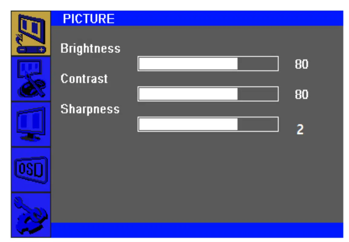
| Brightness (0 ~ 100) | Increases/decreases monitor Brightness. Default: 100 |
| Contrast (0 ~ 100) | Increases/decreases monitor Contrast. Default: 100 |
| Sharpness (0 ~ 4) | Adjusts Sharpness of the displayed images. Default : 2 |
2) COLOR
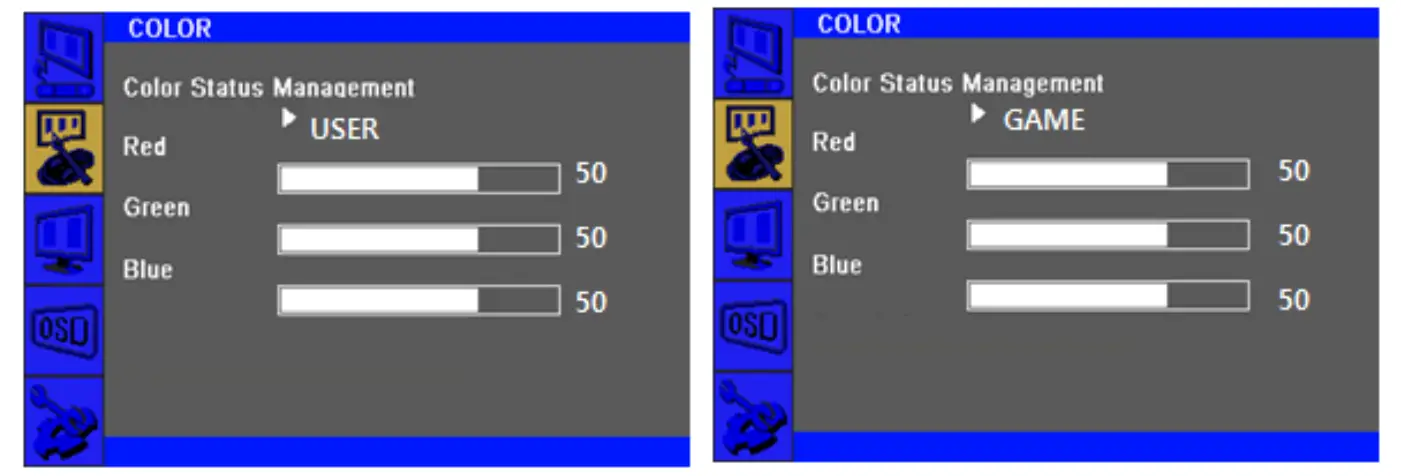
| Color Status Management | Selects the display’s color temperature. The available color settings “Normal”, “Warm”, “Cool”, “User”, “Game” mode. Default : User |
| Red (0 ~ 100) | Increases/decreases Red Color Temperature. Default : 50 |
| Green (0 ~ 100) | Increases/decreases Green Color Temperature. Default : 50 |
| Blue (0 ~ 100) | Increases/decreases Blue Color Temperature. Default : 50 |
3) OSD
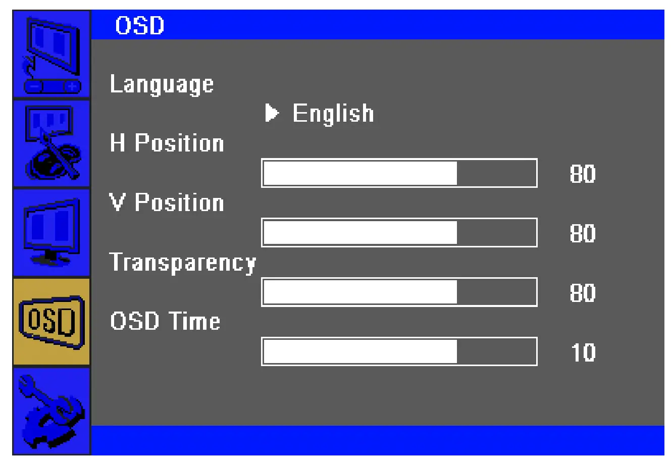
| Language | Selects the OSD’s display language. The available languages are English, Deutsch, Français, Italiano, Español, Korean. Default : English |
| H Position (0 ~ 100) | Adjusts the horizontal location of the OSD menus on the display. Default : 50 |
| V Position (0 ~ 100) | Adjusts the vertical location of the OSD menus on the display. Default : 50 |
| Transparency (0 ~ 100) | Adjusts the transparency of the OSD menus on the display. Default : 33 |
| OSD Time (0 ~ 60) | Adjusts how long the touch monitor will wait without OSD button activity before closing the OSD. The adjustable range is between 0 and 60 seconds. Default : 10 |
4) SETUP
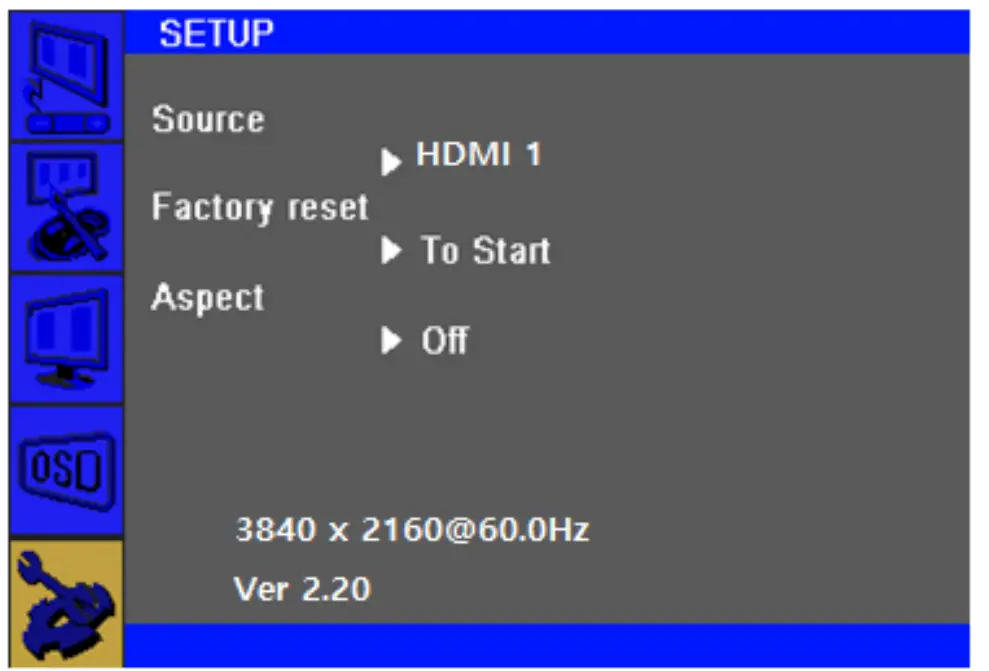
5) Input Source
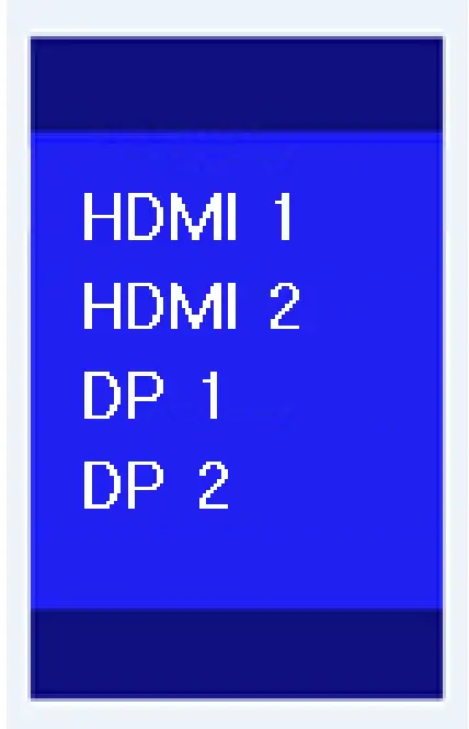
| Source | Selects Input Source HDMI1, HDMI2, DP1, DP2 |
| Factory reset | Restores all factory default settings for OSD-adjustable parameters and for Preset Video Mode timings. |
| Aspect | Switches the scaling method between Full Scaling and Maintain Aspect Ratio. Default : Off |
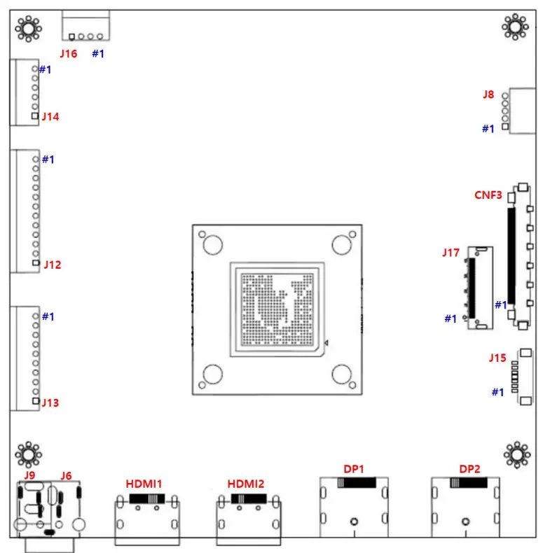
Connector Description
Summary
| Reference | Item | Description | Component | Manufacture |
| DP2 | Jack | DP Input Jack | DP-20P | – |
| DP1 | Jack | DP Input Jack | DP-20P | – |
| HDMI2 | Jack | HDMI Input Jack | HDMI-19P | |
| HDMI1 | Jack | HDMI Input Jack | HDMI-19P | |
| J6 | Jack | 24VDC Power Input Jack | KPJ-4S-S | |
| J9 | Jack | 12VDC Power Input Jack (Optional) | DJ05H-250 | |
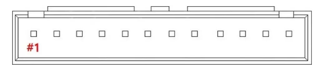
| J13 | Wafer | Main Power / SMPS Power Input Connector | SMAW250-10 | YEON-HO |
| J12 | Wafer | Backlight Inverter Connector | SMAW250-12 | YEON-HO |
| J14 | Wafer | 12VDC/5VDC External Power Output Connector | SMAW250-06 | YEON-HO |
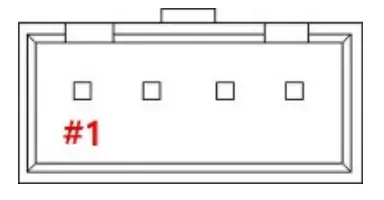
| J16 | Wafer | Panel Power Output Connector | SMAW250-04 | YEON-HO |
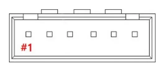
| J8 | Wafer | Auto-Dimming/RS232 Connector | SMAW200-05 | YEON-HO |
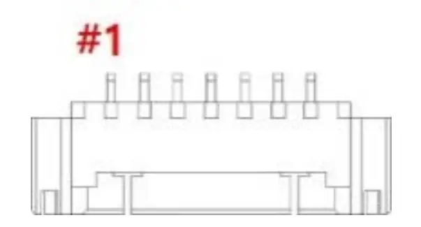
| CNF3 | Wafer | V By One Output(8Lane) Connector | FI-RE51S-HF | YEON-HO |
| J17 | Wafer | eDP Output(4Lane/8Lane) Connector | 20347-040E | I-PEX |
| J15 | Wafer | OSD Board Connector | 12505WR-07 | YEON-HO |
DP2: DP 1.2 (Display Port) Input Jack

| Pin No. | Symbol | Description |
| 1 | LANE3- | Component Signal for Main Link 3 |
| 3 | LANE3+ | True Signal for Main Link 3 |
| 4 | LANE2- | Component Signal for Main Link 2 |
| 6 | LANE2+ | True Signal for Main Link 2 |
| 7 | LANE1- | Component Signal for Main Link 1 |
| 9 | LANE1+ | True Signal for Main Link 1 |
| 10 | LANE0- | Component Signal for Main Link 0 |
| 12 | LANE0+ | True Signal for Main Link 0 |
| 13 | CA DET | No Connection |
| 14 | DP DET+ | No Connection |
| 15 | AUX CH+ | True Signal for Auxiliary Channel |
| 17 | AUX CH- | Component Signal for Auxiliary Channel |
| 18 | +5V Power | Identify the presence of a monitor |
| 19 | RETURN | No Connection |
| 20 | PWR OUT | No Connection |
| 16 | GND | Ground |
DP1: DP 1.2 (Display Port) Input Jack
| Pin No. | Symbol | Description |
| 1 | LANE3- | Component Signal for Main Link 3 |
| 3 | LANE3+ | True Signal for Main Link 3 |
| 4 | LANE2- | Component Signal for Main Link 2 |
| 6 | LANE2+ | True Signal for Main Link 2 |
| 7 | LANE1- | Component Signal for Main Link 1 |
| 9 | LANE1+ | True Signal for Main Link 1 |
| 10 | LANE0- | Component Signal for Main Link 0 |
| 12 | LANE0+ | True Signal for Main Link 0 |
| 13 | CA DET | No Connection |
| 14 | DP DET+ | No Connection |
| 15 | AUX CH+ | True Signal for Auxiliary Channel |
| 17 | AUX CH- | Component Signal for Auxiliary Channel |
| 18 | +5V Power | Identify the presence of a monitor |
| 19 | RETURN | No Connection |
| 20 | PWR OUT | No Connection |
| 16 | GND | Ground |
HDMI2: HDMI 2.0 Input Jack
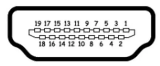
| Pin No. | Symbol | Description |
| 1 | TMDS DATA2+ | TMDS DATA2 Differential Positive Signal |
| 2 | GND | Ground |
| 3 | TMDS DATA2- | TMDS DATA2 Differential Negative Signal |
| 4 | TMDS DATA1+ | TMDS DATA1 Differential Positive Signal |
| 5 | GND | Ground |
| 6 | TMDS DATA1- | TMDS DATA1 Differential Negative Signal |
| 7 | TMDS DATA0+ | TMDS DATA0 Differential Positive Signal |
| 8 | GND | Ground |
| 9 | TMDS DATA0- | TMDS DATA0 Differential Negative Signal |
| 10 | TMDS CLOCK+ | TMDS CLOCK Differential Positive Signal |
| 11 | GND | Ground |
| 12 | TMDS CLOCK- | TMDS CLOCK Differential Negative Signal |
| 13 | CEC | CEC Function |
| 14, 17 | NC | No Connection |
| 15 | DDC Clock | DDC Clock Signal |
| 16 | DDC data | DDC Data Signal |
| 18 | +5V Power | +5V Power |
| 19 | HPD | Hot Plug Detection |
HDMI1: HDMI 2.0 Input Jack
| Pin No. | Symbol | Description |
| 1 | TMDS DATA2+ | TMDS DATA2 Differential Positive Signal |
| 2 | GND | Ground |
| 3 | TMDS DATA2- | TMDS DATA2 Differential Negative Signal |
| 4 | TMDS DATA1+ | TMDS DATA1 Differential Positive Signal |
| 5 | GND | Ground |
| 6 | TMDS DATA1- | TMDS DATA1 Differential Negative Signal |
| 7 | TMDS DATA0+ | TMDS DATA0 Differential Positive Signal |
| 8 | GND | Ground |
| 9 | TMDS DATA0- | TMDS DATA0 Differential Negative Signal |
| 10 | TMDS CLOCK+ | TMDS CLOCK Differential Positive Signal |
| 11 | GND | Ground |
| 12 | TMDS CLOCK- | TMDS CLOCK Differential Negative Signal |
| 13 | CEC | CEC Function |
| 14, 17 | NC | No Connection |
| 15 | DDC Clock | DDC Clock Signal |
| 16 | DDC data | DDC Data Signal |
| 18 | +5V Power | +5V Power |
| 19 | HPD | Hot Plug Detection |
J6: 24V Power Input Jack (Optional)
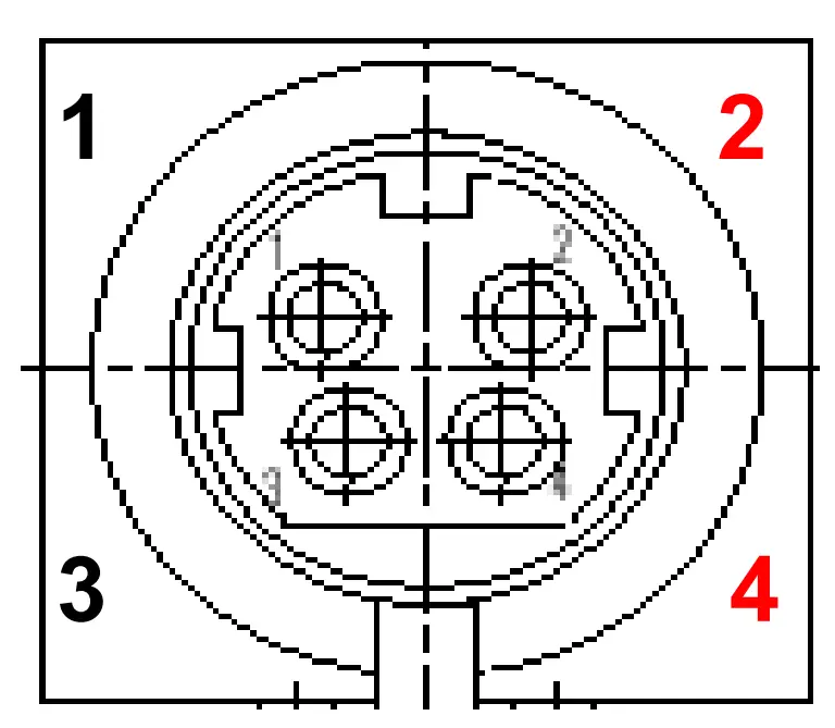
| Pin No. | Symbol | Description |
| 1,3 | GND | Ground |
| 2,4 | VCC | 24VDC |
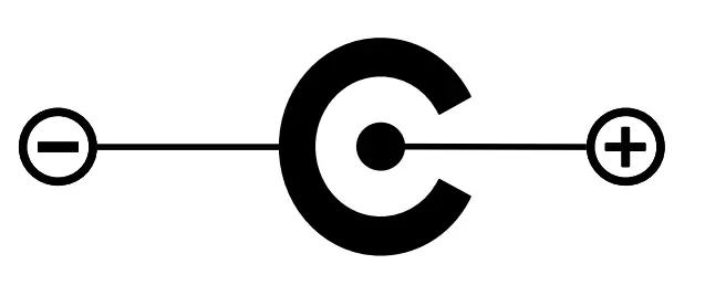
J9 : 12V Power Input Jack (Optional)
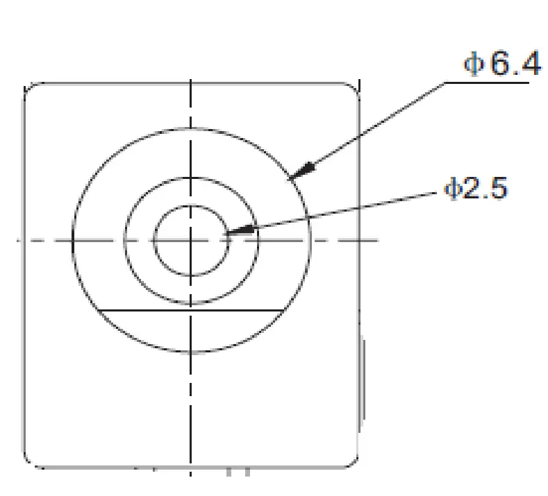
| Pin No. | Symbol | Description |
| – | GND | Ground |
| + | VCC | 12VDC |
J13: Main Power / SMPS Power Connector
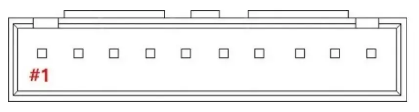
| Pin No. | Symbol | Description |
| 1, 2, 3, 4, 5 | VCC | 24VDC |
| 6, 7, 8, 9,10 | GND | Ground |
J12: Backlight Inverter Connector
| Pin No. | Symbol | Description |
| 1, 2, 3, 4, 5 | VCC | 24VDC |
| 6, 7, 8, 9,10 | GND | Ground |
| 11 | INVERTER ON/OFF | Inverter On(3.3V) / Off(0V) Signal |
| 12 | DIM-ADJUST | DIM-adjustment analog dimming control signal. * make sure inverter specification |
10 J14: 12VDC / 5VDC External Power Output Connector
| Pin No. | Symbol | Description |
| 1, 2, 3 | +12V | 12VDC Output |
| 4 | +5V | 5VDC Output |
| 5,6 | GND | Ground |
J16: Panel Power Output Connector
| Pin No. | Symbol | Description |
| 1, 2 | PANEL_VDD | 12VDC Output for Panel or FRC Power |
| 3, 4 | GND | Ground |
J8: Auto-Dimming / RS232 Connector
| Pin No. | Symbol | Description |
| 1 | VCC | +5V Power for RS232 |
| 2 | CDS | Light Sensor Input |
| 3 | TXD | RX232 TX |
| 4 | RXD | RX232 RX |
| 5 | GND | Ground |
CNF3: V By One Output (8Lane) Connector
| Pin No. | Symbol | Description |
| 1 | GND | Ground |
| 2 | VTX_TX7P | VTX_TX7P |
| 3 | VTX_TX7N | VTX_TX7N |
| 4 | GND | Ground |
| 5 | VTX_TX6P | VTX_TX6P |
| 6 | VTX_TX6N | VTX_TX6N |
| 7 | GND | Ground |
| 8 | VTX_TX5P | VTX_TX5P |
| 9 | VTX_TX5N | VTX_TX5N |
| 10 | GND | Ground |
| 11 | VTX_TX4P | VTX_TX4P |
| 12 | VTX_TX4N | VTX_TX4N |
| 13 | GND | Ground |
| 14 | VTX_TX3P | VTX_TX3P |
| 15 | VTX_TX3N | VTX_TX3N |
| 16 | GND | Ground |
| 17 | VTX_TX2P | VTX_TX2P |
| 18 | VTX_TX2N | VTX_TX2N |
| 19 | GND | Ground |
| 20 | VTX_TX1P | VTX_TX1P |
| 21 | VTX_TX1N | VTX_TX1N |
| 22 | GND | Ground |
| 23 | VTX_TX0P | VTX_TX0P |
| 24 | VTX_TX0N | VTX_TX0N |
| 25 | GND | Ground |
| 26 | VTX_PLL_ Lock | VTX_PLL_ Lock |
| 27 | VTX_HPD | V-by-One Hot Plug Detect |
| 28 | GND | Ground |
| 29 | V-by-one Bit Select | V-by-One 8bit/10bit Select |
| 30 | NC | LED Enable(Optional) |
| 31 | GND | No Connection |
| 32 | SDA | V-by-One IICSDA |
| 33 | SCL | V-by-One IICSCL |
| 34 | NC | No Connection |
| 35 | AUX_CH_P2 | AUX_CH_P2 |
| 36 | AUX_CH_N2 | AUX_CH_N2 |
| 37 | GND | Ground |
| 38 | AUX_CH_P1 | AUX_CH_P1 |
| 39 | AUX_CH_N1 | AUX_CH_N1 |
| 40, 41, 42 | GND | Ground |
| 43 | NC | No Connection |
| 44, 45, 46, 47, 48, 49, 50, 51 | PANEL_VDD | 12VDC Output for Panel |
14 J17: eDP Output(4Lane/8Lane) Connector
| Pin No. | Symbol | Description |
| 1, 2, 3 | PANE_VDD | 12VDC Output for Panel |
| 4 | NC | No Connection |
| 5 ,6,7 | GND | Ground |
| 8, 9, 10 | NC | No Connection |
| 11 | eDP1_HPD | TX HPD1 |
| 12 | 2nd_AUXP | 2nd TX_AUX_P |
| 13 | 2nd_AUXN | 2nd TX_AUX_N |
| 14 | GND | Ground |
| 15 | DPTX_L7P | DPTX_L7P |
| 16 | DPTX_L7N | DPTX_L7N |
| 17 | GND | Ground |
| 18 | DPTX_L6P | DPTX_L6P |
| 19 | DPTX_L6N | DPTX_L6N |
| 20 | GND | Ground |
| 21 | DPTX_L5P | DPTX_L5P |
| 22 | DPTX_L5N | DPTX_L5N |
| 23 | GND | Ground |
| 24 | DPTX_L4P | DPTX_L4P |
| 25 | DPTX_L4N | DPTX_L4N |
| 26 | eDP0_HPD | TX HPD0 |
| 27 | 1st_AUXP | 1stTX_AUX_P |
| 28 | 1st_AUXN | 1stTX_AUX_N |
| 29 | GND | Ground |
| 30 | DPTX_L3P | DPTX_L3P |
| 31 | DPTX_L3N | DPTX_L3N |
| 32 | GND | Ground |
| 33 | DPTX_L2P | DPTX_L2P |
| 34 | DPTX_L2N | DPTX_L2N |
| 35 | GND | Ground |
| 36 | DPTX_L1P | DPTX_L1P |
| 37 | DPTX_L1N | DPTX_L1N |
| 38 | GND | Ground |
| 39 | DPTX_L0P | DPTX_L0P |
| 40 | DPTX_L0N | DPTX_L0N |
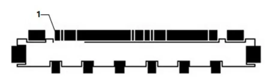
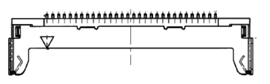
15 J15: OSD Controller Connector
| Pin No. | Symbol | Description |
| 1 | VCC | +5V Power for IR sensor |
| 2 | IRQ | Infrared rays signal line. |
| 3 | LED1 | Green LED |
| 4 | LED2 | Red LED |
| 5 | GND | Ground |
| 6 | ADC-IN0 | Menu, Up |
| 7 | ADC-IN1 | Power, Down, Up |
Standard Display Modes
| Spec Mode | Pixel Freq. | Horizontal Timing | Vertical Timing | ||||||
| Sync Polar | Freq. | Total | Active | SP | Freq. | Total | Active | ||
| MHz | KHz | Pixel | Pixel | Hz | Line | Lind | |||
| 720*400@ 70Hz | 28.287 | N | 31.430 | 900 | 720 | P | 70.000 | 449 | 400 |
| 640*480@60Hz | 28.175 | N | 31.469 | 800 | 640 | N | 59.940 | 525 | 480 |
| 640*480@72Hz | 31.500 | N | 37.861 | 832 | 640 | N | 72.809 | 520 | 480 |
| 640*480@75Hz | 31.500 | N | 37.500 | 840 | 640 | N | 75.000 | 500 | 480 |
| 800*600@60Hz | 40.000 | P | 37.879 | 1056 | 800 | P | 60.317 | 628 | 600 |
| 800*600@72Hz | 50.000 | P | 48.077 | 1040 | 800 | P | 72.188 | 666 | 600 |
| 800*600@75Hz | 49.500 | P | 46.875 | 1056 | 800 | P | 75.000 | 625 | 600 |
| 1024*768@60Hz | 65.000 | N | 48.363 | 1344 | 1024 | N | 60.005 | 806 | 768 |
| 1024*768@ 70Hz | 75.000 | N | 56.476 | 1328 | 1024 | P | 70.070 | 806 | 768 |
| 1024*768@75Hz | 78.750 | P | 60.023 | 1312 | 1024 | P | 75.030 | 800 | 768 |
| 1280*720@60Hz | 74.500 | P | 44.772 | 1664 | 1280 | P | 59.855 | 748 | 720 |
| 1366*768@60Hz | 84.75 | P | 47.72 | 1776 | 1366 | P | 59.799 | 798 | 768 |
| 1280*1024@60Hz | 108.000 | P | 63.981 | 1688 | 1280 | P | 60.020 | 1066 | 1024 |
| 1280*1024@75Hz | 135.000 | P | 79.976 | 1688 | 1280 | P | 75.035 | 1066 | 1024 |
| 1600*900@60Hz | 97.750 | P | 55.540 | 1760 | 1600 | N | 59.948 | 926 | 900 |
| 1680*1050@60Hz | 119.125 | P | 64.742 | 1840 | 1680 | N | 59.946 | 1080 | 1050 |
| 1920*1080@60Hz | 138.625 | P | 66.647 | 2080 | 1920 | N | 59.988 | 1111 | 1080 |
| 1920*1200@60Hz | 154.125 | P | 74.099 | 2080 | 1920 | N | 59.999 | 1235 | 1200 |
| 2560*1600@60Hz | 268.500 | P | 98.713 | 2720 | 2560 | N | 60.010 | 1641 | 1600 |
| 3840*2160@60Hz | 585.980 | P | 129.600 | 4480 | 3840 | 60.000 | 2180 | 2160 | |
LED Backlight Driver Board Specification
Electrical Specification
| Parameter | Symbol | Values | U n it | Remark | ||||
| Min | Typ | Max | ||||||
| Power Supply lnput Voltage | VBL | 2 1 .6 | 24_0 | 26-4 | Vdc | |||
| Power Supply Input Current | IBL | – | – | 7 | A | |||
| P o w er S u p p ly In p ut C u r re n t ( In – r u s h ) | In – ru s h | – | – | 1 0 | A | |||
| Power Consumption | PBL | – | – | 152 | w | |||
| Input Voltage For Control System S ig n a ls | On/Ofl | On | Von | 2_5 | – | 5.25 | Vdc | |
| Ofl | Voff | -0_ 3 | – | 0 . 8 | Vdc | |||
| Brightness Adjust | ExtVBR-B | 10 | – | 100 | % | On Duty | ||
| P u ls e D u ty L e v e l (P W M ) | Hi.g h L e v e l | 2_5 | – | 5.25 | Vdc | H IG H : On d u ty L O W : Off d u ty | ||
| Low L e v e l | o_o | – | 0 . 7 | Vdc | ||||
| P W M Freq. | 100 | 240 | Hz | |||||
| Duty | 10 | – | 100 | % | ||||
Interface
CN100 Connector: 20010WR-14 (YeonHo) or EQ
| Pin | Symbol | Remarks |
| 1,2,3,4,5 | Vin | Input Voltage 24VDC |
| 6,7,8,9,10 | GND | GND |
| 11 | NC | No Connection |
| 12 | On/Off | Backlight On/Off (5V:On, 0V : Off) |
| 14 | PDIM | External PWM |
CN101 Connector: 20010WR-12 (Yeon Ho) or EQ
| Pin | Symbol | Remarks |
| 1,2,3,4,5 | Vin | Input Voltage 24VDC |
| 6,7,8,9,10 | GND | GND |
| 11 | NC | No Connection |
| 12 | NC | No Connection |
Board Dimensions
AD Board (INB3000 V2) Dimension (140mm x 140mm x 21.6mm)
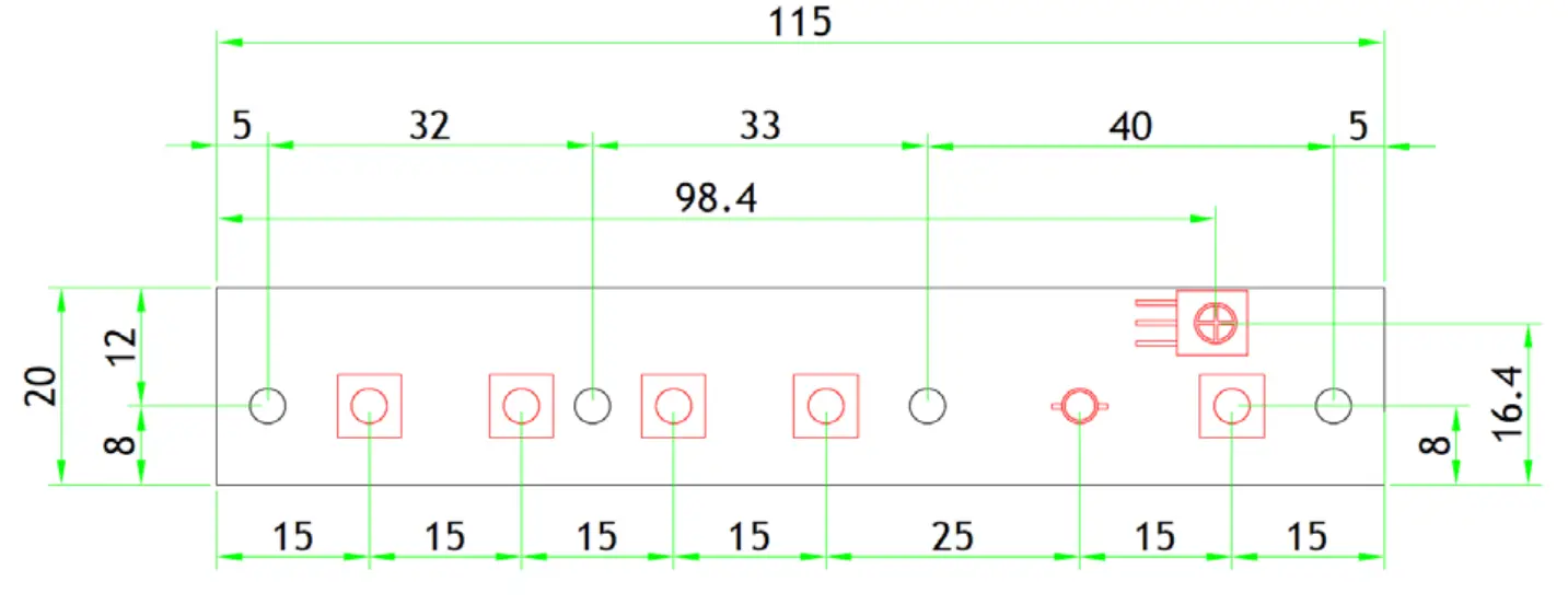
OSD Board (K002) Dimension (115mm x 20mm x 8.7mm)
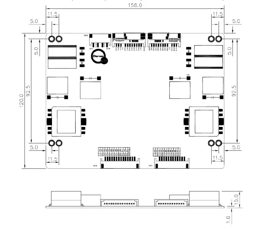
LED Driver Board (GP-1520LD) Dimension (158.0mm x 120mm x 15.0mm)
P-CAP Touchscreen Specification
Touch Controller Specification
| I t e m s | Description | N o t ,e |
| O p era t in g V o lt a,g ,e | +SV | DC (Seria l: Ex t e rn al) |
| Response Tim e | <10ms | |
| Ch an nels | M ax.Tx:66 Rx:1 1 6 channels | Up to 65 “ |
| In t e rf ace Type | USB 2.0 (V ID : 257 5, PI D : 87 6 1 ) – PI ID: C h an g e ab le | H I D / M o u s e M o d e |
| RS23 2 ( Dr iv e r: 3M IMT7) | 3M Compatible | |
| Accuracy | 99% | |
| Support Po in t | 10 point s | Serial:1 – Point |
| Special Function | Water/ Palm / Object rejection Basic(Water/ Palm) | Advanced Tun in g |
| F/W Version | TBD | |
| Powerconsu m p t io n (m A) | Active Mode : < 180mA | |
| Diagnostic function | Su p p o rt s w it h LED | F- Version |
| Recovery function | W atc h d o g (P- so c) | F- Version |
| Operating Temperature | – 20 to 80 °C | |
| Storage e Temperature | – 4 0 to 85 oc |
Features
a. Maximum 182 Channels with Tx66 and Rx116 for Projected Capacitive Touchscreen Panel
b. External power source(serial only): +5V(DC)
c. OS: Windows XP/7/8/10, Android, Linux
d. Supports High Voltage Driving 84 Sensing Channels
e. The BTC-B(F-Ver) supports interface with USB and UART
f. The BTC-B(F-Ver) supports recovery function with watchdog
g. Advanced Water & Palm Rejection Functions Support
h. Diagnostic Function(Intuitive diagnostic function with LED)
i. Supports F/W Upgrade & Inspection Tool
Touch Control Board Dimension (130.0mm x 50.0mm)

Touch Controller USB Interface
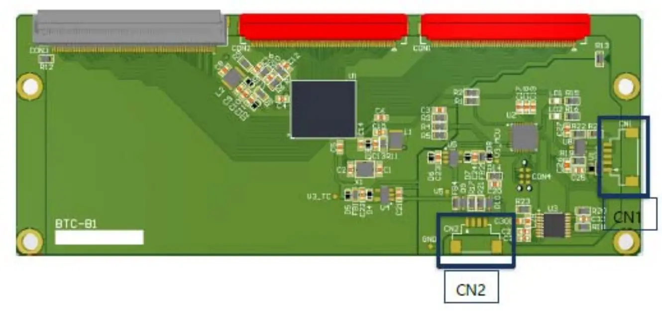
| CN2 = Se,ria l(F-Versi on) 12507WR 04L(YEONHO) | |
| PilN No. | Description |
| 1 | VDD{SV) |
| 2 | TXD |
| 3 | RXD |
| 4 | GND |
| CN1 = USB 12507WR-05L (YEONHO)i | |
| P1IN No. | IDescriptii on |
| 1 | GND(Frame) |
| 2 | VDD{SV) |
| 3 | GND |
| 4 | D+ |
| 5 | D – |
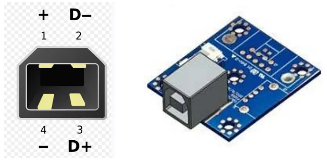
USB Connector (USB 2.0, Type “B”)
| Number | Signal Name |
| 1 | +5V |
| 2 | D- |
| 3 | D+ |
| 4 | GND |
Touch Screen Dimension (751.4mm x 1260.84mm x 4.5mm)
USB Interface Port
Packing Information Item
| Item | Q’ty | Dimension (W x H x D) | Weight(Kg) | Remark |
| Open Frame | 1Pcs | 751.4mm x 1260.84mm x 203.43mm | TBD | |
| Box Packing | TBD | |||
| Pallet Size | TBD | |||
| Pallet Packing | TBD |