![]()
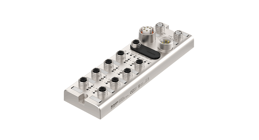
Remote I/O Boxes (PROFINET)
ADIO-PN
PRODUCT MANUAL 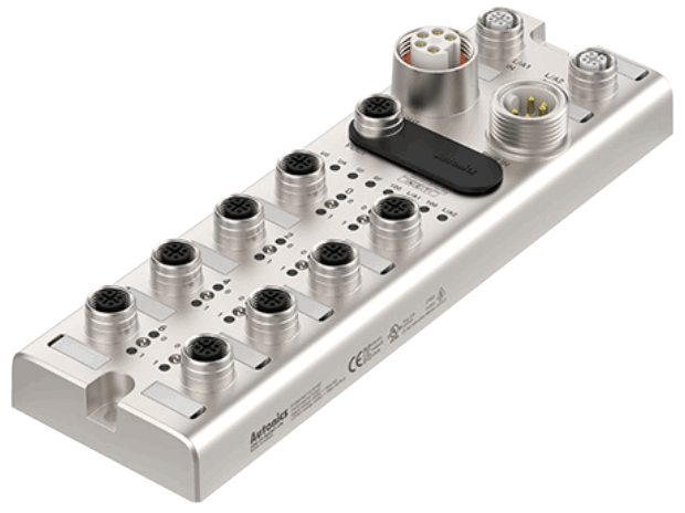
For your safety, read and follow the considerations written in the instruction manual, other manuals and Autonics website.
The specifications, dimensions, etc. are subject to change without notice for product improvement. Some models may be discontinued without notice.
Features
- The upper level communication protocol: PROFINET
- The lower level communication protocol:10-1_41k ver. 1.1 (port class: Class A)
- Housing m aterial: Zinc Die casting
- Protection rating: IP67
- The daisy chain allows tile power supply usingthe connection technology in a standardized 7/8” connector
- The maximum output current of power supply: 2 A per port
- I/O port settings and status monitoring (cable short/ disconnection, connection status, etc.)
- Supports digital input filter
Safety Considerations
- Observe all ‘Safety Considerations’ for safe and proper operation to avoid hazards.
 symbol indicates caution due to special circumstances in which hazards may occur. Warning Failure to follow instructions may result in serious injury or death.
- Fail-safe device must be installed when using the unit with machinery that may cause serious injury or substantial economic loss.(e.g. nuclear power control, medical equipment, ships, vehicles, railways, aircraft, combustion apparatus, safety equipment, crime/disaster prevention devices, etc.) Failure to follow this instruction may result in personal injury, economic loss or fire.
- Do not use high humidity, unitcl? te in thetstlplace gt, radiant heat, flammable/explosive/corrosive ‘ay( ‘lays may be present. Failure to follow this instruction may result in explosion or fire.
- Do not connect, repair, or inspect the unit while connected to a power source. Failure to follow this instruction may result in fire.
- Check ‘Connections’ before wiring. Failure to follow this instruction may result in fire.
- Do not disassemble or modify the unit Failure to follow this instruction may result in fire.
- Do not touch the product during operation or for a certain period of time after stopping.
Failure to follow this instruction may result in bum.
![]() Caution Failure to follow instructions may result in injury or product damage.
Caution Failure to follow instructions may result in injury or product damage.
- Use the unit within the rated specifications. Failure to follow this instruction may result in fi rear shortening the life cycle of the product.
- Use a dry cloth to clean the unit, and do not use water or organic solvent. Failure to follow this instruction may result in fire.
- Keep the product away from metal chip, dust, and wire residue which flow into the unit. Failure to follow this instruction may result in fireor product damage.
- Connect the cable correctly and prevent poor contact Failure to follow this instruction may result in fi re or product damage.
- Do not connect or cut off the wire of the cable while operating the unit Failure to follow this instruction may result in fire or product damage.
Cautions during Use
- Follow instructions in ‘Cautions during Use: Otherwise, it may cause unexpected accidents.
- The LA power (actuator power) and US power (sensor power) should be insulated by the individually isolated power device.
- Power supply should be insulated and limited voltage/current or Class 2, SELV power supply device.
- Use the rated standard cables and connectors. Do not apply excessive pogger when connecting or disconnecting the connectors of the product.
- Keep away from high voltage lines or power lines to prevent inductive noise. In case installing power line and input signal line closely, use line filter orvaristor at power line and shielded wire at input signal fine. For stable operation, use shield wire and ferrite core, when wiring communication wire, power wire, or signal wire.
- Do not use near the equipment which generates strong magnetic force or high frequency noise.
- Do not connect, or remove this unit while connected to a power source.
- This unit may be used in the following environments.
– Indoors (in the environment condition fated in ‘Specifications’)
-Altitude max. 2,000m - Pollution degree 2
– Installation category II
Configuration of ADIO-PN
The figure below shows the PROFINET network and the devices that compose it.
For proper use of the product, refer to the manuals and be sure to follow the safety considerations in the manuals.
Download the manuals from the Autonics website.
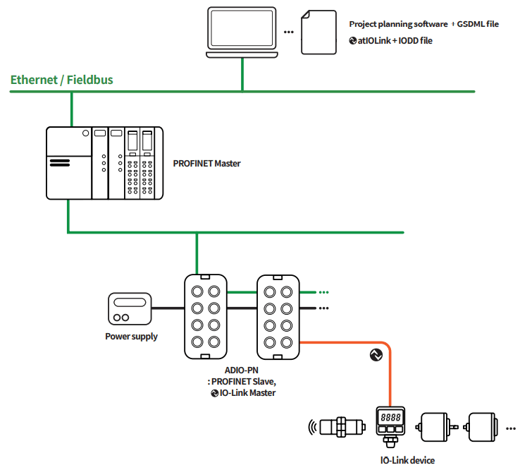
01) The project planning software of the upper level communication system may be different depending on the user’s environment.
For more information, refer to the manufacturer’s manual.
■ The supported parameters
| Operation mode | Safe State 01) | Validation | Data Storage | Input Filter 01) | Vendor ID | Device ID | Cycle Time |
| Digital Input | – | – | – | ○ | – | – | – |
| Digital Output | ○ | – | – | – | – | – | – |
| 10-Link Input | – | ○ | ○ | – | ○ | ○ | ○ |
| 10-Link Output | – | ○ | ○ | – | ○ | ○ | ○ |
| 10-Link Input/Output | – | ○ | ○ | – | ○ | ○ | ○ |
Ordering Information
This is only for reference, the actual product does not support all combinations.
For selecting the specified model, follow the Autonics website.

❶ I/O specification
N: NPN
P: PNP
Product Components
- Product (+ Protective cover for the rotary switches)
- Name plates × 20
- M4×10 screw with washer × 1
- Instruction manual × 1
- Waterproof cover × 4
Sold Separately
- Name plates
- Waterproof cover
Software
Download the installation file and the manuals from the Autonics website.
- atIOLink
atIOLink with purposes for setting, diagnosis, initialization and maintenance of IO-Link device via IODD file is provided as the dedicated Port and Device onfiguration Tool (PDCT).
Connections
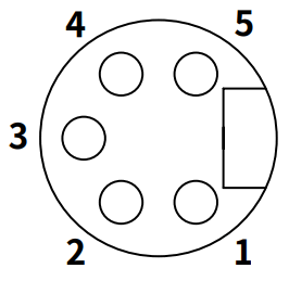
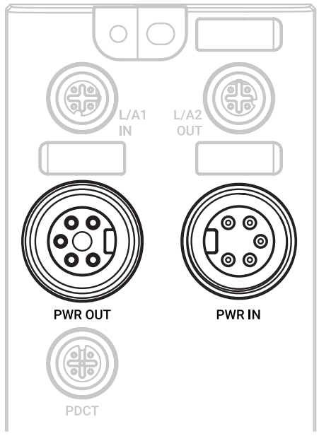
■ Ethernet port
| M12 (Socket-Female), D-coded | Pin | Function | Description |
 | 1 | TX + | Transmit Data + |
| 2 | RX + | Receive Data + | |
| 3 | TX – | Transmit Data – | |
| 4 | RX – | Receive Data – |
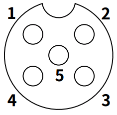
■ Power supply port
| OUT (7/8″, Socket- Female) | IN (7/8″, Plug-Male) | Pin | Function | Description |
 |  | 1, 2 | 0 V | Sensor and actuator supply |
| 3 | F.G. | Frame ground | ||
| 4 | +24 VDC | Sensor supply | ||
| 5 | +24 VDC | Actuator supply |
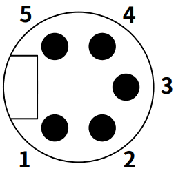
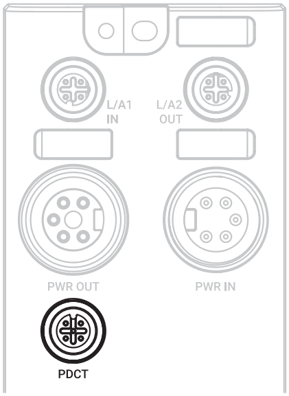
■ PDCT port
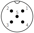
| i M12 (Socket-Female), A-coded | Pin | Function |
 | 1 | Not Connected (N.C.) |
| 2 | Data- | |
| 3 | 0 V | |
| 4 | Not Connected (N.C.) | |
| 5 | Data + |
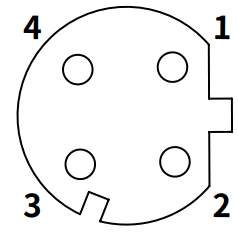
■ I/O port
| M12 (Socket-Female), A-coded | Pin | Function |
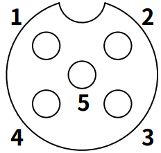 | 1 | +24 VDC |
| 2 | I/Q: Digital Input | |
| 3 | 0 V | |
| 4 | C/Q: 10-Link, Digital Input/Output | |
| 5 | Not Connected (N.C.) |
Dimensions
- Unit: mm, For the detailed dimensions of the product, follow the Autonics website.
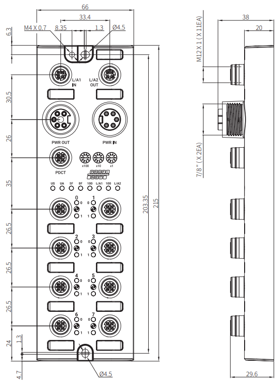
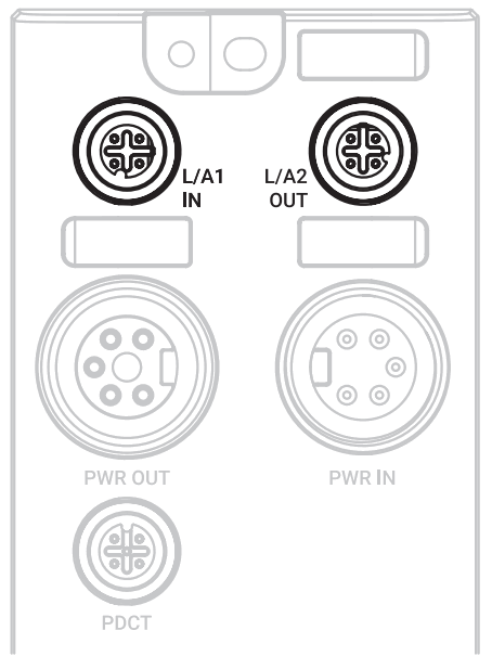
Unit Descriptions
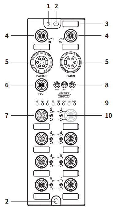
| 01. Grounding hole 02. Mounting hole 03. Insertion part for the name plate 04. Ethernet port 05. Power supply port | 06. PDCT port 07. I/O port 08. Rotary switches 09. Status indicator 10. I/O port indicator |
Installation
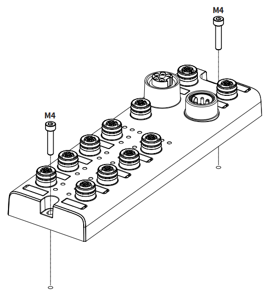
■ Mounting
- Prepare a flat or metal panel in the enclosure.
- Drill a hole to mount and ground the product on the surface.
- Turn off all power.
- Fix the product using M4 screws in the mounting holes.
Tightening torque: 1.5 N m
■ Grounding
![]() Be sure to use a cable with low impedance and as short as possible for connecting the housing to the product.
Be sure to use a cable with low impedance and as short as possible for connecting the housing to the product.
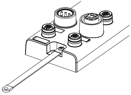
- Connect the grounding strap and M4×10 screw with washer.
- Fix the screw in the grounding hole.
Tightening torque: 1.2 N m
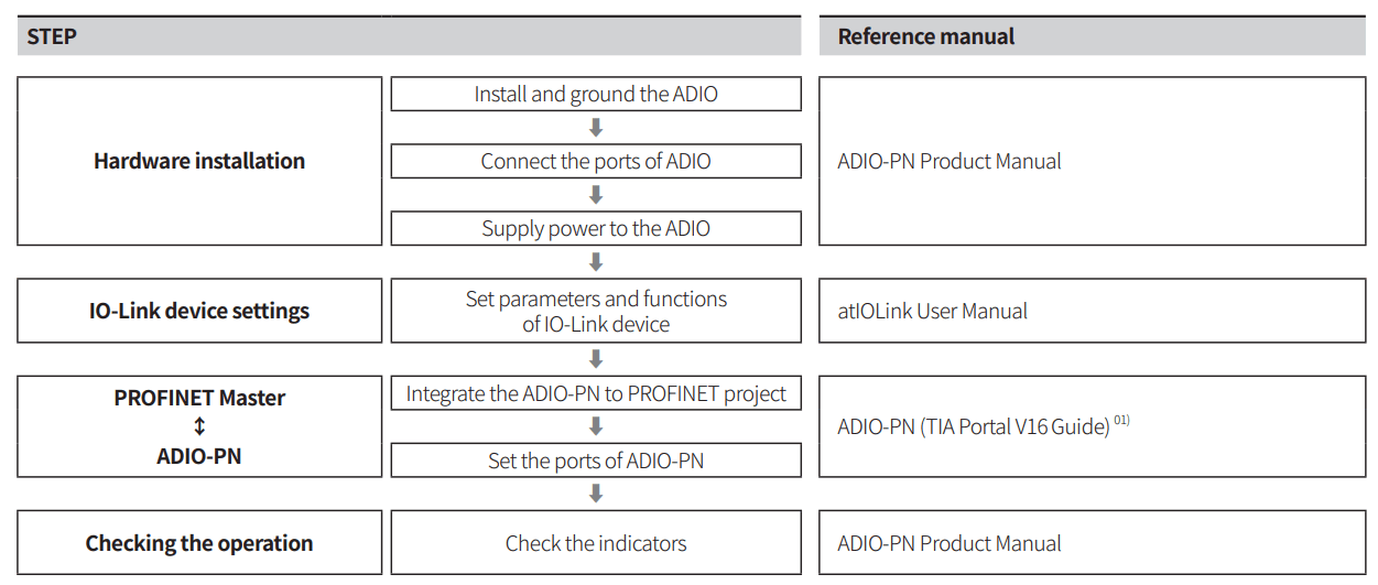
Device Name Settings
To connect to the PROFINET network, configure the PROFINET interface. The PROFINET device name can be configured using the following methods.
- Rotary switches
![]() Be sure to place the seal of the protective cover firmly on the rotary switches after completing the settings.
Be sure to place the seal of the protective cover firmly on the rotary switches after completing the settings.
The protection rating is not guaranteed when the protective cover is open.
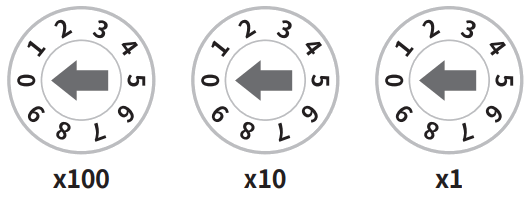
- Rotate the rotary switches to set the device name. The green LED of the US indicator flashes.
Setting mode Rotary switches Description Value PROFINET Device Name 0 This device name is stored in the ADIO-PN’s EEPROM.
Applying the device name configured on the PROFINET Master or DCP tools.PROFINET device name 001 to 999 Establish the communication connection after setting the ADIO-PN’s device name. The value of rotary switches is displayed at the last of the device name. ADIO-PN-MA08A-ILM- - Turn on the ADIO-PN again.
- Check that green LED of the US indicator is ON.
- The device name has been changed.
- Put the protective cover on the rotary switches.
■ atIOLink
The PROFINET device name configured by the atIOLink software is stored in the ADIO-PN’s EEPROM. For more information, refer to the atIOLink User Manual.
Port Connections
■ Port specifications
- Be sure to check the port specifications below before connecting the device. Prepare a cable that complies with the protection rating IP67.
| Ethernet port | I/O port | PDCT port | Power supply port | |
| Type | M12 (Socket-Female), 4-pin, D-coded | M12 (Socket-Female), 5-pin, A-coded | M12 (Socket-Female), 5-pin, A-coded | Input: 7/8″ (Plug-Male), 5-pin Output: 7/8″ (Socket-Female), 5-pin |
| Push-Pull | YES | YES | YES | N.A |
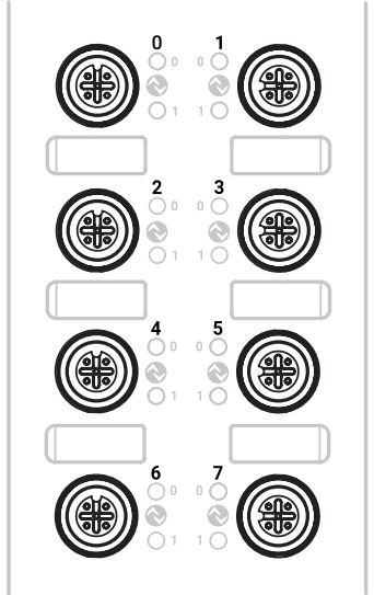
| Number of ports | 2 | 8 | 1 | 2 |
| Tightening torque | 0.6 N m | 0.6 N m | 0.6 N m | 1.5 N m |
| Supported function | Daisy chain | USB serial communication | Daisy chain |
- The example of communication cable for the PDCT port
| Connector 1 | Connector 2 | Wiring |
 M12 (Plug-Male), 5-pin M12 (Plug-Male), 5-pin | 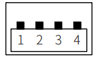 USB Type A (Plug-Male) USB Type A (Plug-Male) | 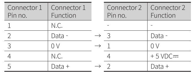 |
- Connect to the PROFINET
 01. Connect the M12 connector to the Ethernet port. See the connections below.
1 TX + Transmit Data + 2 RX + Receive Data + 3 TX – Transmit Data – 4 RX – Receive Data – 02. Connect the connector to the PROFINET network.
• Network device: PLC or PROFINET device supporting PROFINET protocol
03. Put the waterproof cover on the unused port. - Connect the IO-Link devices The maximum output current is 2 A at each I/O port. Configure the device so that the total current of the I/O ports does not exceed 9 A. Check the wiring information in the manual of the IO-Link device to be connected.
 01. Connect the M12 connector to the I/O port. See the connections below.
1 +24 VDC 
2 I/Q: Digital Input 3 0 V 4 C/Q: 10-Link, Digital Input/Output 5 Not Connected (N.C.) 02. Put the waterproof cover on the unused port.
- Connect with the atIOLink Do not use the PDCT port and the Ethernet port at the same time.
 01. Connect the M12 connector to the PDCT port. See the connections below.
1 Not Connected (N.C.) 2 Data – 3 0 V 4 Not Connected (N.C.) 5 Data + 02. Connect the connector to the network device.
• Network device: PC/laptop that atIOLink software is installed
03. Put the waterproof cover on the unused port. - Connect the power supply to ADIO Be sure not to exceed 9 A of the maximum supplying current to the sensor (US).
 01. Turn off all power.
02. Connect the 7/8″ connector to the power supply port. See the connections below.
 01. Connect the M12 connector to the Ethernet port. See the connections below.
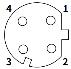
 01. Connect the M12 connector to the I/O port. See the connections below.
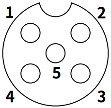
 01. Connect the M12 connector to the PDCT port. See the connections below.
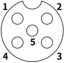
 01. Turn off all power.
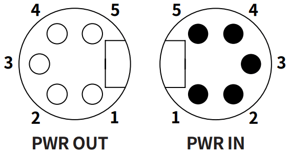
| 1, 2 | 0 V | Sensor and actuator supply |
| 3 | F.G. | Frame ground |
| 4 | +24 VDC | Sensor supply |
| 5 | +24 VDC | Actuator supply |
Indicators
■ Status indicator

- The power supply of sensor
Indicator LED color Status Description US Green
ON Applied voltage: normal Flashing (1 Hz) The settings of the rotary switches is changing. Red Flashing (1 Hz) Applied voltage: low (< 18 VDC ) - The power supply of actuator
Indicator LED color Status Description UA Green ON Applied voltage: normal Red Flashing (1 Hz) Applied voltage: low (< 18 VDC ), Error in the rotary switchesON Applied voltage: none (< 10 VDC ) - Product initialization
Indicator LED color Status Description US, UA Red ON ADIO initialization failure - System failure
Indicator LED color Status Description SF Red OFF No error ON Watchdog timeout, system error Flashing DCP signal service is initiated via the bus. - Bus failure
Indicator LED color Status Description BF Red OFF No error ON Low speed of physical link or no physical link Flashing No data transmission or configuration settings - Ethernet connection
Indicator LED color Status Description L/A1 L/A2 Green
OFF No Ethernet connection ON The Ethernet connection is established. Yellow Flashing Data transmission - Transmission rate of the Ethernet
Indicator LED color Status Description 100 Green ON Transmission rate: 100 Mbps
■ I/O port indicator

- Pin 4 (C/Q)
Indicator LED color Status Description 0 Yellow
OFF DI/DO: pin 4 OFF ON DI/DO: pin 4 ON Green
ON Port configuration: IO-Link Flashing (1 Hz) Port configuration: IO-Link, No IO-Link device found Red Flashing (2 Hz) IO-Link configuration error
• Validation failed, Invalid data length, Data Storage errorON • NPN: Short circuit occurred on the output of pin 4 and pin 1
• PNP: Short circuit occurred on the output of pin 4 and pin 3 - Pin 2 (I/Q)
Indicator LED color Status Description 1 Yellow OFF DI: pin 2 OFF ON DI: pin 2 ON - The power supply of the I/O port
Indicator LED color Status Description 0,1 Red Flashing (1 Hz) Short circuit occurred in the I/O supply power (pin 1, 3)
Specifications
■ Electrical/Mechanical specifications
| Supply voltage | 18 – 30 VDC |
| Rated voltage | 24 VDC |
| Current consumption | 2.4 W ( ≤ 216 W) |
| Supplying current per port | ≤ 2 A/Port |
| Sensor current (US) | ≤ 9 A |
| Dimensions | W 66 × H 215 × D 38 mm |
| Material | Zinc Die casting |
| Ethernet port | M12 (Socket-Female), 4-pin, D-coded, Push-Pull Number of ports: 2 (IN/OUT) Supported function: daisy chain |
| Power supply port | Input: 7/8” (Plug-Male), 5-pin Output: 7/8” (Socket-Female), 5-pin Number of ports: 2 (IN/OUT) Supported function: daisy chain |
| PDCT port | M12 (Socket-Female), 5-pin, A-coded, Push-Pull Number of ports: 1 Connection method: USB serial communication |
| I/O port | M12 (Socket-Female), 5-pin, A-coded, Push-Pull Number of ports: 8 |
| Mounting method | Mounting hole: fixed with M4 screw |
| Grounding method | Grounding hole: fixed with M4 screw |
| Unit weight (packaged) | ≈ 700 g (≈ 900 g) |
■ Mode specifications
| Mode | Digital Input |
| Number of channels | 16-CH (I/Q: 8-CH, C/Q:8-CH) |
| I/O common | NPN / PNP |
| Input current | 5 mA |
| ON voltage/current | Voltage: ≥ 15 VDC |
| OFF voltage | ≤ 5 VDC |
■ Mode specifications
| Mode | Digital Output |
| Number of channels | 8-CH (C/Q) |
| I/O common | NPN / PNP |
| Power supply | 24 VDC |
| Leakage current | ≤ 0.1 mA |
| Residual voltage | ≤ 1.5 VDC |
| Short circuit protection | YES |
■ Mode specifications
| Mode | IO-Link |
| Input current | 2 mA |
| ON voltage/current | Voltage: ≥ 15 VDC |
| OFF voltage | ≤ 5 VDC |
■ Environmental conditions
| Ambient temperature 01) | -5 to 70 °C, Storage: -25 to 70 °C (no freezing or condensation) |
| Ambient humidity | 35 to 75%RH (no freezing or condensation) |
| Protection rating | IP67 (IEC standard) |
■ Approvals
| Approval | |
| Association approval |
Communication Interface
Ethernet
| Ethernet standard | 100BASE-TX |
| Cable spec. | STP (Shielded Twisted Pair) Ethernet cable over Cat 5 |
| Transmission rate | 100 Mbps |
| Cable length | ≤ 100 m |
| Protocol | PROFINET |
| Address settings | Rotary switches, DCP, atIOLink |
| GSDML file | Download the GSDML file at the Autonics website. |
IO-Link
| Version | 1.1 |
| Transmission rate | COM1 : 4.8 kbps / COM2 : 38.4 kbps / COM3 : 230.4 kbps |
| Port class | Class A |
| Standard | IO-Link Interface and System Specification Version 1.1.2 IO-Link Test Specification Version 1.1.2 |
18, Bansong-ro 5l3Beon-gil, Haeundae-gu, Busan, Republic of Korea, 48002
www.autonics.com I +82-2-2048-1577 I [email protected]
![]()

 User Manual")


