![]()
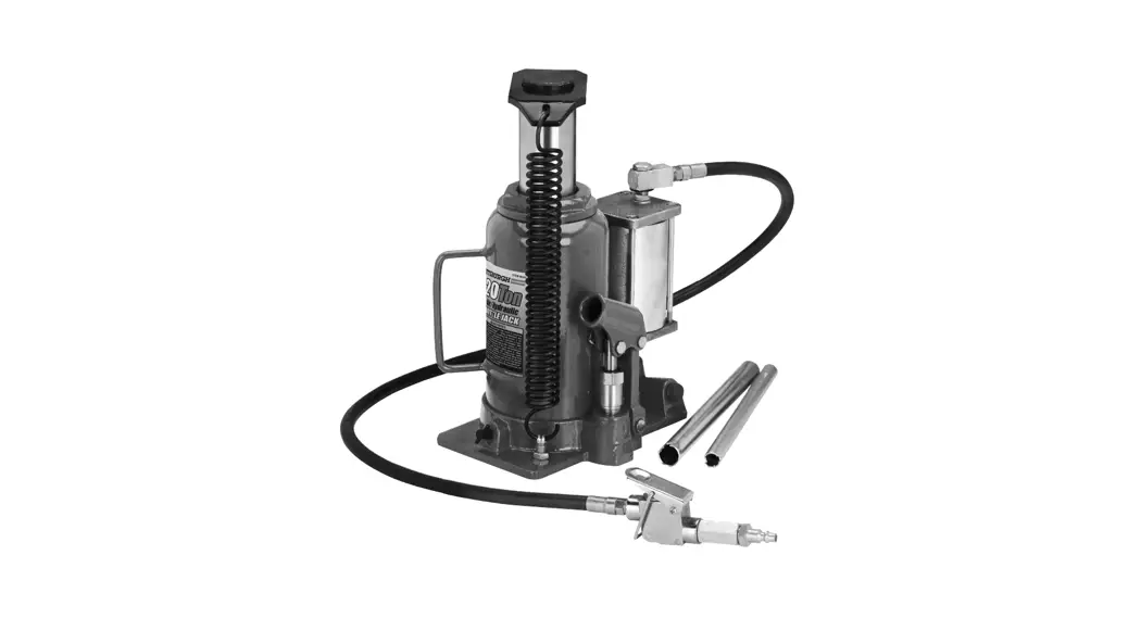
AUTOMOTIVE 95553 20 Ton Capacity Air or Hydraulic Bottle Jack
Owner’s Manual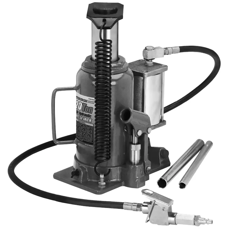
Owner’s Manual & Safety Instructions
Save This Manual Keep this manual for the safety warnings and precautions, assembly, operating, inspection, maintenance and cleaning procedures. Write the product’s serial number in the back of the manual (or month and year of purchase if the product has no number). Keep this manual and the receipt in a safe and dry place for future reference.
Visit our website at: http://www.harborfreight.com email our technical support at: [email protected]
When unpacking, make sure that the product is intact and undamaged. If any parts are missing or broken, please call 18888665797 as soon as possible.
Copyright© 2022 by Harbor Freight Tools®. All rights reserved. No portion of this manual or any artwork contained herein may be reproduced in any shape or form without the express written consent of Harbor Freight Tools. Diagrams within this manual may not be drawn proportionally. Due to continuing improvements, the actual product may differ slightly from the product described herein.
Tools required for assembly and service may not be included.![]() WARNING Read this material before using this product. Failure to do so can result in serious injury.
WARNING Read this material before using this product. Failure to do so can result in serious injury.
SAVE THE MANUAL
SaFety
Warning Symbols and Definitions
![]() This is the safety alert symbol. It is used to alert you to potential personal injury hazards. Obey all safety messages that follow this symbol to avoid possible injury or death.
This is the safety alert symbol. It is used to alert you to potential personal injury hazards. Obey all safety messages that follow this symbol to avoid possible injury or death.![]() CAUTION Indicates a hazardous situation that, if not avoided, will result in death or serious injury.
CAUTION Indicates a hazardous situation that, if not avoided, will result in death or serious injury.![]() WARNING Indicates a hazardous situation that, if not avoided, could result in death or serious injury.
WARNING Indicates a hazardous situation that, if not avoided, could result in death or serious injury.
NOTICE Indicates a hazardous situation that, if not avoided, could result in minor or moderate injury.
CAUTION Addresses practices not related to personal injury.
IMPORTANT SAFETY INSTRUCTIONS
INSTRUCTIONS PERTAINING TO A RISK OF FIRE, ELECTRIC SHOCK, OR INJURY TO PERSONS
Warning When using tools, basic precautions should always be followed, including the following:
General
To reduce the risks of electric shock, fire, and injury to persons, read all the instructions before using the tool.
Work area
- Keep the work area clean and well-lighted. Cluttered benches and dark areas increase the risks of electric shock, fire, and injury to persons.
- Do not operate the tool in explosive atmospheres, such as in the presence of flammable liquids, gases, or dust. The tool is able to create sparks resulting in the ignition of dust or fumes.
- Keep bystanders, children, and visitors away while operating the tool. Distractions are able to result in the loss of control of the tool.
For technical questions, please call 1-888-866-5797.
Personal Safety
- Stay alert. Watch what you are doing and use common sense when operating the tool. Do not use the tool while tired or under the influence of drugs, alcohol, or medication. A moment of inattention while operating the tool increases the risk of injury to persons.
- Dress properly. Do not wear loose clothing or jewelry. contain long hair. Keep hair, clothing, and gloves away from moving parts. Loose clothes, jewelry, or long hair increases the risk of injury to persons as a result of being caught in moving parts.
- Avoid unintentional starting. Be sure the switch is off before connecting to the air supply. Do not carry the tool with your finger on the switch or connect the tool to the air supply with the switch on.
- Do not overreach. Keep proper footing and balance at all times. Proper footing and balance enable better control of the tool in unexpected situations.
 Use safety equipment.
A dust mask, nonskid safety shoes, and a hard hat must be used for the applicable conditions. Always wear eye protection. Wear ANSI-approved safety goggles.
 Always wear hearing protection when using the tool. Prolonged exposure to high-intensity noise is able to cause hearing loss.
Tool use and care
- Use clamps or another practical way to secure and support the workpiece to a stable platform. Holding the work by hand or against the body is unstable and is able to lead to loss of control.
- Do not force the tool. Use the correct tool for the application. The correct tool will do the job better and safer at the rate at which the tool is designed.
- Do not use the tool if the switch does not turn the tool on or off. Any tool that cannot be controlled with the switch is dangerous and must be repaired.
- Disconnect the tool from the air source before making any adjustments, changing accessories, or storing the tool. Such preventive safety measures reduce the risk of starting the tool unintentionally. Turn off and detach the air supply, safely discharge any residual air pressure, release the throttle, and/or turn the switch to its off position before leaving the work area.
- Store the tool when it is idle out of reach of children and other untrained persons. A tool is dangerous in the hands of untrained users.
- Maintain the tool with care. Keep a cutting tool sharp and clean. A properly maintained tool, with sharp cutting edges, reduces the risk of binding and is easier to control.
- Check for misalignment or binding of moving parts, breakage of parts, and any other condition that affects the tool’s operation. If damaged, have the tool serviced before using. Many accidents are caused by poorly maintained tools. There is a risk of bursting if the tool is damaged.
- Use only accessories that are identified by the manufacturer for the specific tool model. Use of an accessory not intended for use with the specific tool model increases the risk of injury to persons.
Service
- Tool service must be performed only by qualified repair personnel.
- When servicing a tool, use only identical replacement parts. use only authorized parts.
- Use only the lubricants supplied with the tool or specified by the manufacturer.
Air Source
-
 Never connect to an air source that is capable of exceeding 200 psi. Over pressurizing the tool may cause bursting, abnormal operation, breakage of the tool or serious injury to persons. Use only clean, dry, regulated compressed air at the rated pressure or within the rated pressure range as marked on the tool. Always verify prior to using the tool that the air source has been adjusted to the rated air pressure or within the rated air pressure range.
 - Never use oxygen, carbon dioxide, combustible gases or any bottled gas as an air source for the tool. Such gases are capable of explosion and serious injury to persons.
Symbology
| Symbol | Property or statement |
| no | No-load speed |
| —Alin | Revolutions or reciprocation per minute |
| PSI | Pounds per square inch of pressure |
| ft-lb | Foot-pounds of torque |
| BPM | Blows per minute |
| CFM | Cubic Feet per Minute flow |
| SCFM | Cubic Feet per Minute flow at standard conditions |
| Symbol | Property or statement |
| NPT | National pipe thread, tapered |
| NPS | National pipe thread, straight |
| WARNING marking concerning Risk of Eye Injury. Wear ANSI-approved eye protection. | |
| WARNING marking concerning Risk of Hearing Loss. Wear hearing protection. | |
| WARNING marking concerning Risk of Respiratory Injury. Wear a NIOSH-approved dust mask/respirator. | |
| WARNING marking concerning Risk of Explosion. |
Specific Safety instructions
- The warnings and precautions discussed in this manual cannot cover all possible conditions and situations that may occur. It must be understood by the operator that common sense and caution are factors that cannot be built into this product but must be supplied by the operator.
- Only use with accessories rated to handle the forces exerted by this tool during operation. Other accessories not designed for the forces generated may break and forcefully launch pieces.
- Attach all accessories properly to the tool before connecting the air supply. A loose accessory may detach or break during operation.
- Obey the manual for the air compressor used to power this tool.
- Install an inline shutoff valve to allow immediate control over the air supply in an emergency, even if a hose is ruptured.
- Use this tool with both hands only. Using tools with only one hand can result in loss of control.
- Lifting device only. Immediately after lifting, support the vehicle with appropriate means.
- Keep clear of load while lifting and lowering.
- Lower load slowly.
- Do not use it for aircraft purposes.
- Apply the parking brake and chock tires before lifting the vehicle.
- Lift vehicle only at manufacturer-recommended locations.
- Bleed the hydraulic system before its initial use.
- When lifting only one wheel, make sure to support load immediately with one jack stand (not included) placed underside of the vehicle being lifted. Align saddle of the jack stand directly under the vehicle’s seam or recommended lifting point.
- When lifting the entire front end or rear end of the vehicle, make sure to support the load immediately with two jack stands. Align saddles of jack stands directly under the vehicle’s frame or recommended lifting points. Also, make sure jack stands are adjusted at the same height.
- Do not use Bottle Jack with the vehicle’s engine running. When running, the vehicle’s engine produces carbon monoxide, a colorless, odorless, toxic gas that, when inhaled, can cause serious personal injury or death.
- Keep hands and feet away from all moving parts of the Bottle Jack when applying or releasing a load. Keep people and animals at a safe distance when using the Bottle Jack.
- Do not allow anyone in the vehicle when using Bottle Jack.
- Do not use Bottle Jacks to lift both ends of a vehicle at the same time.
- Before lowering the Bottle Jack, make sure tool trays, jack stands, and all other tools and equipment are removed from under the vehicles.
- Obey the manual for the air compressor used to power this tool.
- Install an inline shutoff valve to allow immediate control over the air supply in an emergency, even if a hose is ruptured.
![]() SAVE THESE INSTRUCTIONS
SAVE THESE INSTRUCTIONS
Functional Description
Specifications
| Maximum Air Pressure | 120 PSI |
| Air Inlet | 1/4″ -18 NPT |
| Weight Capacity | 20 Tons (40,000 lb.) |
| Maximum Height | 20″ (with screw cap extended) |
| Minimum Height | 10-1/4″ |
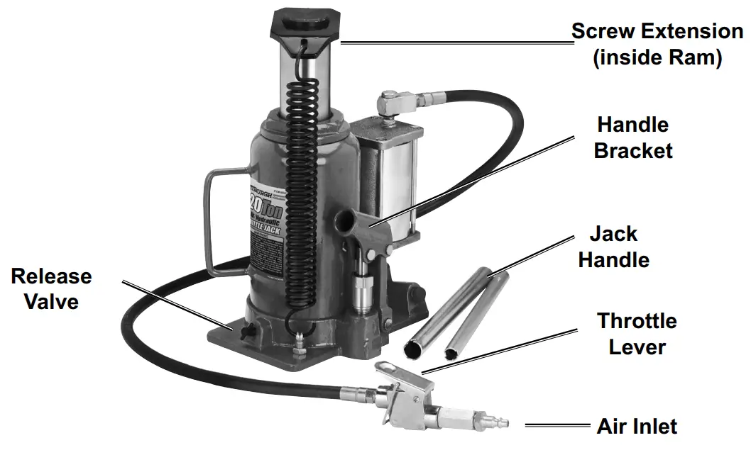
Components and controls
Initial tool Set up/assembly
![]() Read the entire iMpOrtant SaFety inFOrMatiOn section at the beginning of this manual including all text under subheadings therein before setting up or use of this product. Note: For additional information regarding the parts listed in the following pages, refer to the Assembly Diagram near the end of this manual.
Read the entire iMpOrtant SaFety inFOrMatiOn section at the beginning of this manual including all text under subheadings therein before setting up or use of this product. Note: For additional information regarding the parts listed in the following pages, refer to the Assembly Diagram near the end of this manual.
Note: This air tool may be shipped with a protective plug covering the air inlet. Remove this plug before set up.
Air Supply
![]() WARNING
WARNING
![]() TO PREVENT SERIOUS INJURY FROM EXPLOSION: Use only clean, dry, regulated, compressed air to power this tool. Do not use oxygen, carbon dioxide, combustible gases, or any other bottled gas as a power source for this tool.
TO PREVENT SERIOUS INJURY FROM EXPLOSION: Use only clean, dry, regulated, compressed air to power this tool. Do not use oxygen, carbon dioxide, combustible gases, or any other bottled gas as a power source for this tool.
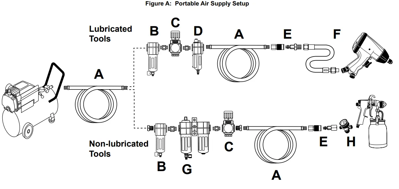
- Incorporate a filter, regulator with pressure gauge, in-line shutoff valve, and quick coupler for best service, as shown on Figure A on page 8 and Figure B on page 9. An in-line shutoff ball valve is an important safety device because it controls the air supply even if the air hose is ruptured. The shutoff valve should be a ball valve because it can be closed quickly.
Note: If an automatic oiler system is not used, add a few drops of Pneumatic Tool Oil to the airline connection before operation. Add a few more drops after each hour of continual use. - Attach an air hose to the compressor’s air outlet. Connect the air hose to the air inlet of the tool. Other components, such as a coupler plug and quick coupler, will make operation more efficient but are not required.
 WARNING! TO PREVENT SERIOUS INJURY FROM ACCIDENTAL OPERATION: Do not install a female quick coupler on the tool. Such a coupler contains an air valve that will allow the air tool to retain pressure and operate accidentally after the air supply is disconnected.
Note Air flow, and therefore tool performance can be hindered by undersized air supply components. The air hose must be long enough to reach the work area with enough extra length to allow free movement while working.
Purging Air From Hydraulic System - Turn the tool’s throttle or switch to the off position; refer to the Operation section for a description of controls.
- Close the in-line shutoff valve between the compressor and the tool.
- Turn on the air compressor according to the manufacturer’s directions and allow it to build up pressure until it cycles off.
- Adjust the air compressor’s output regulator so that the air output is enough to properly power the tool, but the output will not exceed the tool’s maximum air pressure at any time. Adjust the pressure gradually, while checking the air output gauge to set the right pressure range.
- Inspect the air connections for leaks. Repair any leaks found.
- If the tool will not be used at this time, turn off and detach the air supply, safely discharge any residual air pressure, and release the throttle, and/or turn the switch to its off position to prevent accidental operation.
- Residual air pressure should not be present after the tool is disconnected from the air supply. However, it is a good safety measure to attempt to discharge the tool in a safe fashion after disconnecting to ensure that the tool is disconnected and not powered.
Purging Air From Hydraulic System
Note: Before first use, the hydraulic ram may need to be purged. Some air may intrude in the hydraulic system due to movement during shipping. Air bubbles can become trapped inside the hydraulic system, thereby reducing the efficiency of the Jack. Purge air from the system if efficiency drops.
- Place the slotted end of the Jack Handle over the Release Valve and turn 1-1/2 turns counterclockwise.
- Remove the Oil Filler Plug on the side of the Jack Reservoir.
- Rapidly pump the Handle several times to purge air from the hydraulic system.
- Use the Handle to turn the Release Valve screw clockwise until snug
- Top off Jack Reservoir with a high-quality hydraulic jack oil.
| Description | Function | |
| A | Air Hose | Connects air to the tool |
| B | Filter | Prevents dirt and condensation from damaging tool or workpiece |
| C | Regulator | Adjusts air pressure to the tool |
| D | Lubricator (optional) | For air tool lubrication |
| E | Coupler and Plug | Provides quick connection and release |
| F | Leader Hose (optional) | Increases coupler life |
| G | Air Cleaner / Dryer (optional) | Prevents water vapor from damaging the workpiece |
| H | Air Adjusting Valve (optional) | For fine-tuning airflow at the tool |
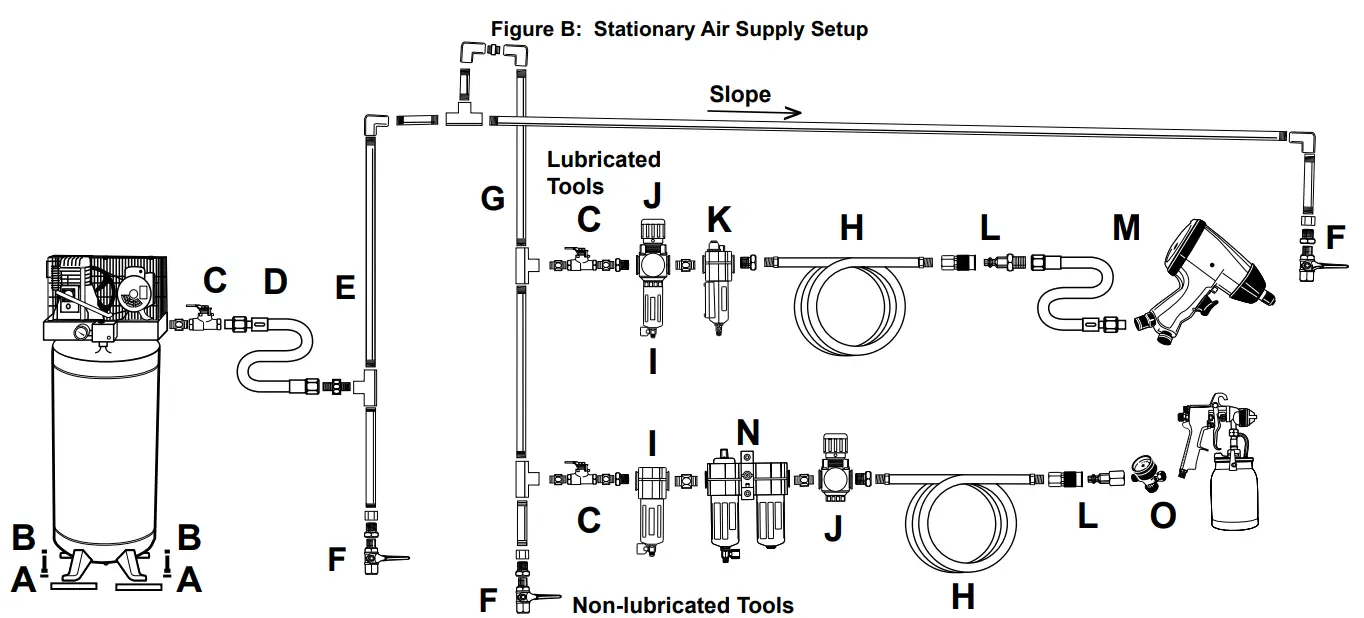
| Description | Function | |
| A | Vibration Pads | For noise and vibration reduction |
| B | Anchor Bolts | Secures air compressor in place |
| C | Ball Valve | Isolates sections of the system for maintenance |
| D | Isolation Hose | For vibration reduction |
| E | Main Air Line ‑ 3/4″ minimum recommended | Distributes air to branch lines |
| F | Ball Valve | To drain moisture from the system |
| G | Branch Air Line ‑1/2″ minimum recommended | Brings air to point of use |
| H | Air Hose | Connects air to the tool |
| I | Filter | Prevents dirt and condensation from damaging tool or workpiece |
| J | Regulator | Adjusts air pressure to the tool |
| K | Lubricator (optional) | For air tool lubrication |
| L | Coupler and Plug | Provides quick connection and release |
| M | Leader Hose (optional) | Increases coupler life |
| N | Air Cleaner / Dryer (optional) | Prevents water vapor from damaging the workpiece |
| O | Air Adjusting Valve (optional) | For fine-tuning airflow at the tool |
Operating
![]() Read the ENTIRE IMPORTANT SAFETY INFORMATION section at the beginning of this manual including all text under subheadings therein before set up or use of this product.
Read the ENTIRE IMPORTANT SAFETY INFORMATION section at the beginning of this manual including all text under subheadings therein before set up or use of this product.
Inspect tool before use, looking for damaged, loose, and missing parts. If any problems are found, do not use tool until repaired.
Tool Set Up![]() WARNING
WARNING
TO PREVENT SERIOUS INJURY FROM ACCIDENTAL OPERATION: Turn off the tool, detach the air supply, safely discharge any residual air pressure in the tool, and release the throttle and/or turn the switch to its off position before performing any inspection, maintenance, or cleaning procedures.
TO PREVENT SERIOUS INJURY: Do not adjust or tamper with any control or component in a way not specifically explained within this manual. Improper adjustment can result in tool failure or other serious hazards.
Before Use
- Park the vehicle on a flat, level, solid, surface safely away from oncoming traffic.
- Turn off the vehicle’s engine.
- Place the vehicle’s transmission in “PARK” (if automatic) or in its lowest gear (if manual). Set the vehicle’s emergency brake.
- Chock the wheels that are not being lifted.
Workpiece and Work Area Set Up
- Designate a work area that is clean and well-lit. The work area must not allow access by children or pets to prevent distraction and injury.
- Route the air hose along a safe route to reach the work area without creating a tripping hazard or exposing the air hose to possible damage. The air hose must be long enough to reach the work area with enough extra length to allow free movement while working.
General Operating Instructions
This is an air-actuated hydraulic bottle jack. The air motor is air pressure activated and drives the hydraulic jack. In the event no air pressure is available, a standard hydraulic piston assembly is provided for hand jacking.
Note: Safety shutoff prevents lifting in excess of rated load.
- Position the Jack on a solid level surface that can withstand the weight of the jack and the load which will be lifted.
- Be sure the load is balanced on the jack. Properly rated jack stands (not included) positioned under the weight provide a good safety precaution against the possibility of the load toppling.
- Be sure that the jack is positioned at a proper lift point on the item to be lifted. Using appropriate lift points avoids possible damage to the item.
- Rotate the Screw Extension on the Ram until it contacts the underside of the load to be lifted. Screwing counterclockwise raises the extension while screwing clockwise lowers the extension.
- Engage the notch on the end of the Jack Handle onto the Release Valve. Turn the Release Valve slightly clockwise to ensure that the valve is closed. The jack will not lift if the valve is open.
- Operation a. Pneumatic Operation: Connect a pressurized air source to the Air Inlet then squeeze the Throttle Lever on the Air Valve to raise the load. b. Manual Operation: Insert the end of the Jack Handle into the Handle Bracket and pump up and down.
- Support the load using jack stands (not included) or other means to support the weight. Do not leave the load on the jack for an extended period of time. Damage to the jack or personal or property injury may result.
- To lower the item, first use the Jack to lift the item slightly and remove the jack stands.
- Engage notches in the end of the Jack Handle onto the Release Valve. Turn the valve approximately 1/4 and turn counterclockwise to lower the load. When the load is lowered, turn the Release Valve clockwise to stop the motion.
- If an automatic oiler is not used, add a few drops of Pneumatic Tool Oil to the airline connection before use. Add a few drops more after each hour of continual use.
- If the tool requires more force to accomplish the task, verify that the tool receives sufficient, unobstructed airflow (CFM) and increases the pressure (PSI) output of the regulator up to the maximum air pressure rating of this tool.
CAUTION! TO PREVENT INJURY FROM TOOL OR ACCESSORY FAILURE: Do not exceed the tool’s maximum air pressure rating. If the tool still does not have sufficient force at maximum pressure and sufficient airflow, then a larger tool may be required. - To prevent accidents, turn off the tool, detach the air supply, safely discharge any residual air pressure in the tool, release the throttle, and/ or turn the switch to its off position after use. Clean external surfaces of the tool with a clean, dry cloth, and apply a thin coat of tool oil. Then store the tool indoors out of children’s reach.
Maintenance
![]() Procedures not specifically explained in this manual must be performed only by a qualified technician.
Procedures not specifically explained in this manual must be performed only by a qualified technician.![]() WARNING
WARNING
TO PREVENT SERIOUS INJURY FROM ACCIDENTAL OPERATION: Turn off the tool, detach the air supply, safely discharge any residual air pressure in the tool, and release the throttle and/or turn the switch to its off position before performing any inspection, maintenance, or cleaning procedures.
TO PREVENT SERIOUS INJURY FROM TOOL FAILURE: Do not use damaged equipment. If abnormal noise, vibration, or leaking air occurs, have the problem corrected before further use.
Cleaning, Maintenance, and Lubrication
Note: These procedures are in addition to the regular checks and maintenance explained as part of the regular operation of the air-operated tool.
- BEFORE EACH USE, inspect the general condition of the tool. Check for:
• loose hardware or housing,
• misalignment or binding of moving parts,
• cracked or broken parts, and
• any other condition that may affect its safe operation. - Daily – Air Supply Maintenance: Every day, maintain the air supply according to the component manufacturers’ instructions. Drain the moisture filter regularly. Performing routine air supply maintenance will allow the tool to operate more safely and will also reduce wear on the tool.
- Quarterly (every 3 months) —Tool Disassembly, Cleaning, and Inspection: Have the internal mechanism cleaned, inspected, and lubricated by a qualified technician.
- Periodically check the air and hydraulic fittings for leaks. Repair if any leak is detected.
- Periodically lubricate all moving points of the Jack.
- The Hydraulic Ram should be kept clean, free of dirt and water, and protected from corrosion.
- OIL REPLACEMENT:
a. Place Jack in an upright position.
b. Completely lower the Ram.
c. Remove the Filler Plug and keep it clean.
d. Fill the Reservoir with high-quality hydraulic jack oil to the lower rim of the fill hole.
e. Purge air from the hydraulic system as previously described on Purging Air From Hydraulic System on page 7.
f. Top off with more hydraulic oil.
g. Replace Filler Plug.
Troubleshooting
| Problem | Possible Causes | Likely Solutions |
| Decreased output. | 1. Not enough air pressure and/ or airflow. 2. Obstructed trigger. 3. Blocked air inlet screen (if equipped). 4. Air leaking from loose housing. 5. Mechanism contaminated. | 1. Check for loose connections and make sure that the air supply is providing enough airflow (CFM) at the required pressure (PSI) to the tool’s air inlet. Do not exceed maximum air pressure. 2. Clean around the trigger to ensure free movement. 3. Clean air inlet screen of buildup. 4. Make sure housing is properly assembled and tight. 5. Have a qualified technician clean and lubricate the mechanism. Install the in-line filter in the air supply as stated in Setup: Air Supply. |
| Severe air leakage. (Slight air leakage is normal, especially on older tools.) | 1. Cross-threaded housing components. 2. Loose housing. 3. Damaged valve or housing. 4. Dirty, worn or damaged valve. | 1. Check for incorrect alignment and uneven gaps. If cross-threaded, disassemble and replace damaged parts before use. 2. Tighten housing assembly. If housing cannot tighten properly, internal parts may be misaligned. 3. Replace damaged components. 4. Clean or replace valve assembly. |
| Jack does not lift. | 1. Open Release Valve. 2. Leak in air system. 3. Leak in the hydraulic system. 4. Air pump mechanism stuck. 5. Dirty, worn or damaged seals. | 1. Close Release Valve. Engage the notches at the end of the Jack Handle onto the Release Valve and turn clockwise. 2. Make sure housing is properly assembled and tight. 3. Have qualified service technicians repair or replace leaking components. 4. Open Release Valve, then operate the Air Level fully. 5. Have a qualified service technician inspect Jack for faults and possible repairs. |
![]() WARNING
WARNING
TO PREVENT SERIOUS INJURY: Use caution when troubleshooting a malfunctioning Jack. Stay well clear of the supported load. Completely resolve all problems before use. If the solutions presented in the Troubleshooting guide do not solve the problem, have a qualified technician inspect and repair the Jack before use.
AFTER THE JACK IS REPAIRED: Test It carefully without a load by raising and lowering It fully, checking for proper operation,
BEFORE RETURNING THE JACK TO OPERATION. DO NOT USE A DAMAGED OR MALFUNCTIONING JACK!
| POSSIBLE SYMPTOMS | PROBABLE SOLUTION (Make certain that Jack is not supporting a load while attempting a solution.) | |||||
| Jack will not lift at its weight capacity | Saddle lowers under load | Pump stroke feels spongy | The saddle will not lift all the way | Handle moves up when the jack is under load | Oil leaking from filler plug | |
| X | X | Check that Release Valve is fully closed. Bleed air from the system. | ||||
| X | X | X | Valves may be blocked and may not close fully. To flush the valves: 6. Lower the Saddle and securely close the Release Valve. 7. Manually lift the saddle several inches. 8. Open the release valve and force the saddle down as quickly as possible. | |||
| X | X | X | Jack may be low on oil. Check the oil level and refill if needed. | |||
| Jack may require bleeding – see Purging Air From Hydraulic Systems on page 7. | ||||||
| X | The unit may have too much hydraulic oil inside, check the fluid level, and adjust if needed. | |||||
PLEASE READ THE FOLLOWING CAREFULLY
THE MANUFACTURER AND/OR DISTRIBUTOR HAS PROVIDED THE PARTS LIST AND ASSEMBLY DIAGRAM IN THIS MANUAL AS A REFERENCE TOOL ONLY. NEITHER THE MANUFACTURER NOR DISTRIBUTOR MAKES ANY REPRESENTATION OR WARRANTY OF ANY KIND TO THE BUYER THAT HE OR SHE IS QUALIFIED TO MAKE ANY REPAIRS TO THE PRODUCT, OR THAT HE OR SHE IS QUALIFIED TO REPLACE ANY PARTS OF THE PRODUCT. IN FACT, THE MANUFACTURER AND/OR DISTRIBUTOR EXPRESSLY STATE THAT ALL REPAIRS AND PARTS REPLACEMENTS SHOULD BE UNDERTAKEN BY CERTIFIED AND LICENSED TECHNICIANS, AND NOT BY THE BUYER. THE BUYER ASSUMES ALL RISK AND LIABILITY ARISING OUT OF HIS OR HER REPAIRS TO THE ORIGINAL PRODUCT OR REPLACEMENT PARTS THERETO OR ARISING OUT OF HIS OR HER INSTALLATION OF REPLACEMENT PARTS THERETO.
Record Product’s Serial Number Here:
Note: If the product has no serial number, record the month and year of purchase instead.
Note: Some parts are listed and shown for illustration purposes only, and are not available individually as replacement parts. Specify UPC 193175046536 when ordering parts.
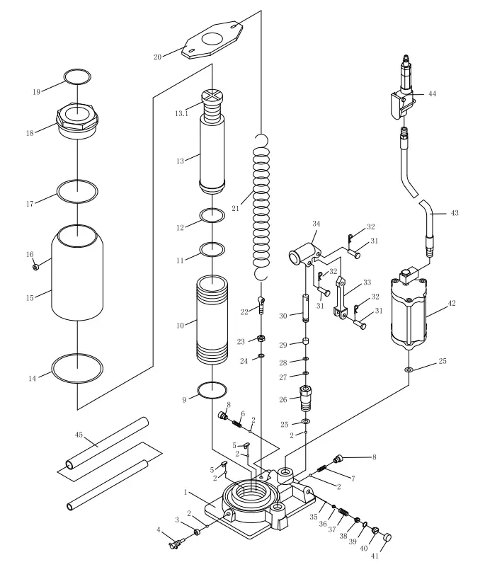
Parts List and Diagram
| Part | Description | Qty | Part | Description | Qty | Part | Description | Qty | ||
| 1 | Base | 1 | 16 | Filler Plug | 1 | 32 | R‑Pin | 3 | ||
| 2 | Ball | 6 | 17 | Nylon Ring | 1 | 33 | Connector | 1 | ||
| 3 | Seal | 1 | 18 | Top Nut | 1 | 34 | Handle Bracket | 1 | ||
| 4 | Release Valve | 1 | 19 | O‑Ring | 1 | 35 | Ball | 1 | ||
| 5 | Ball Cup | 2 | 20 | Spring Plate | 1 | 36 | Ball Cup | 1 | ||
| 6 | Spring | 1 | 21 | Return Spring | 2 | 37 | Spring | 1 | ||
| 7 | Spring | 1 | 22 | Eye Bolt | 2 | 38 | Screw | 1 | ||
| 8 | Screw | 2 | 23 | Nut | 2 | 39 | O‑Ring | 1 | ||
| 9 | Nylon Ring | 1 | 24 | Lock Washer | 2 | 40 | Screw | 1 | ||
| 10 | Cylinder | 1 | 25 | Washer | 2 | 41 | Cup | 1 | ||
| 11 | O‑Ring | 1 | 26 | Pump Cylinder | 1 | 42 | Air Motor | 1 | ||
| 12 | Cup Seal | 1 | 27 | O‑Ring | 1 | 43 | Air Hose | 1 | ||
| 13 | Ram | 1 | 28 | Nylon Ring | 1 | 44 | Air Valve | 1 | ||
| 13.1 | Extension Screw | 1 | 29 | Backup Ring | 1 | 45 | Handle | 2 | ||
| 14 | Packing | 1 | 30 | Piston | 1 | |||||
| 15 | Reservoir | 1 | 31 | Pin | 3 | |||||
Limited 90-Day Warranty
Harbor Freight Tools Co. makes every effort to assure that its products meet high quality and durability standards, and warrants to the original purchaser that this product is free from defects in materials and workmanship for the period of 90 days from the date of purchase. This warranty does not apply to damage due directly or indirectly, to misuse, abuse, negligence or accidents, repairs or alterations outside our facilities, criminal activity, improper installation, normal wear, and tear, or to lack of maintenance. We shall in no event be liable for death, injuries to persons or property, or for incidental, contingent, special or consequential damages arising from the use of our product. Some states do not allow the exclusion or limitation of incidental or consequential damages, so the above limitation of exclusion may not apply to you. THIS WARRANTY IS EXPRESSLY IN LIEU OF ALL OTHER WARRANTIES, EXPRESS OR IMPLIED, INCLUDING THE WARRANTIES OF MERCHANTABILITY AND FITNESS.
To take advantage of this warranty, the product or part must be returned to us with transportation charges prepaid. Proof of purchase date and an explanation of the complaint must accompany the merchandise. If our inspection verifies the defect, we will either repair or replace the product at our election or we may elect to refund the purchase price if we cannot readily and quickly provide you with a replacement. We will return repaired products at our expense, but if we determine there is no defect, or that the defect resulted from causes not within the scope of our warranty, then you must bear the cost of returning the product. This warranty gives you specific legal rights and you may also have other rights which vary from state to state.
![]() 26677 agoura road
26677 agoura road
calabasas, ca 91302
1-888-866-5797


