VIVIDHORSE VTR-22-MU-30-9TW-A LED Troffer Retrofit Luminaire
Installation Warnings
- To reduce the risk of death, personal injury, property damage from fire, electric shock, falling parts, cuts/abrasions, and other hazards make sure to read all warnings and instructions included with and on the fixture box and all fixture labels.
- Follow these general precautions before installing, servicing, or performing routine maintenance upon this equipment.
- Commercial installation, service, and maintenance of luminaires should be performed by a qualified licensed electrician.
- LED Retrofit kit installation requires knowledge of luminaires electrical systems. If not qualified, do not attempt installation. Contact a qualified electrician.
- To prevent wiring damage or abrasion, do not expose wiring to edges of sheet metal or other sharp objects.
- Do not make or alter any open holes in an enclosure of wiring or electrical components during kit installation
Warnings
- Turn off electrical power at fuse or circuit breaker box before wiring fixture to the power supply.
- Turn off the power prior to performing any maintenance
- Verify that the supply voltage is correct by comparing it with the luminaire label information.
- All wiring connections should be capped with UL approved wire connectors
Caution
- Avoid direct eye exposure to the light source while it is on.
- Account for small parts and properly dispose of packing material, as these may be hazardous to children.
- Risk of burn. Disconnect power and allow fixture to cool before changing bulb or handling fixture.
- The green ground screw is installed in its proper location. Do not Relocate.
- Please use minimum 90°C rated supply conductors.
- Specifications and dimensions subject to change without notice.
- Suitable for Dry and Damp location, Type IC.
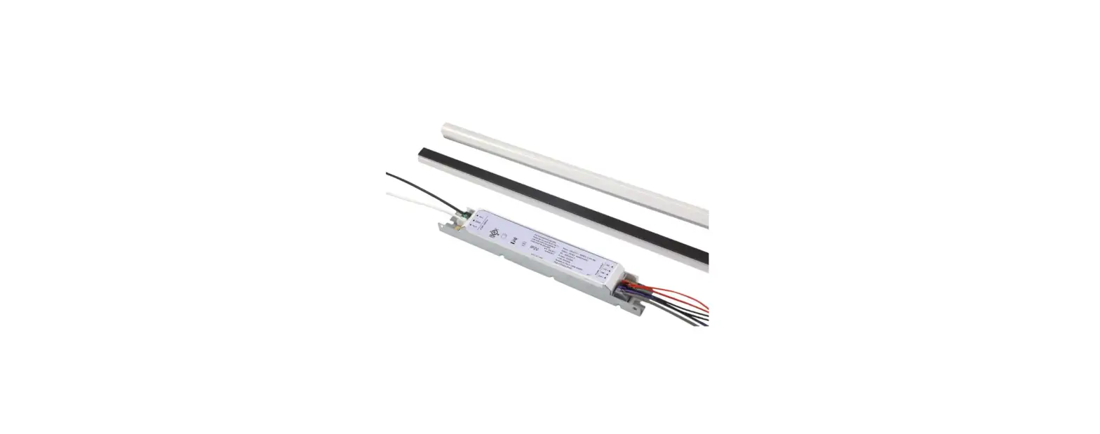
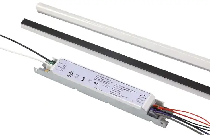
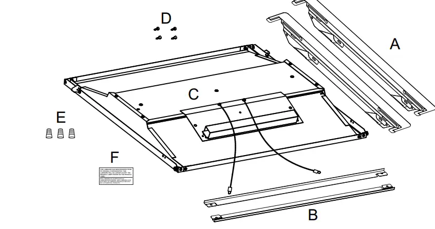
Retrofit Kit Components
- A: End Brackets…………………………..2pcs
- B: Side Brackets………………………….2pcs
- C: Retrofit KitHousing…………………..1pcs
- D: #8 x 1/2” Self-Taping Screws…….4pcs
- E: Wire Caps………………………………3pcs
- F: Retrofit Label…………………………..1pcs

NOTE: The existing fluorescent luminaries housing shall be larger than dimensions described in below table: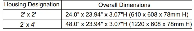
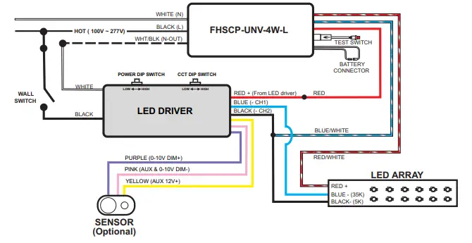
General Wiring Diagram
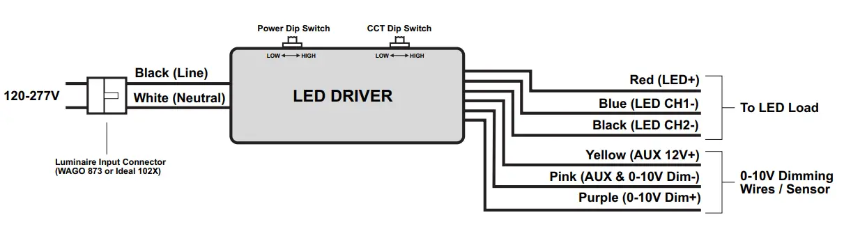
Field-Adjustable Wattage & CCT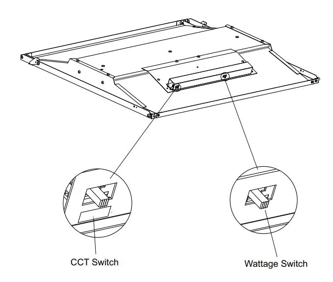
Adjustable lumen output and color temperature can be set to the desired output using the two DIP switches shown above. Each DIP switch has 3 options (Low, Medium and High) corresponding to the three available color temperatures and power levels.
- DIP switches are located on the side of the retrofit kit housing.
- Select a wattage and temperature by sliding each switch left or right to set the desired value.
- See below for available options:
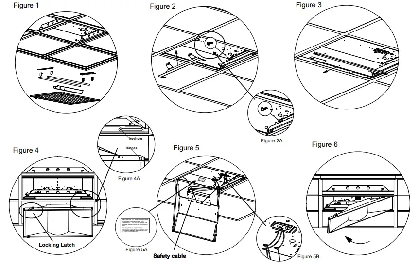
Installation
- Prior to installation, disconnect all incoming power to the fixture. Remove existing hardware
- Leave supply and grounding leads.
- Follow all federal and local regulations when disposing of lamps and removed components.
- Install the end brackets to each end of the existing fixture by gently lifting the fixture and placing the end brackets between the fixture and T-grid.
- If you are not pleased with the side gap between the fixture and T-grid, you may install the side brackets between the fixture and T-grid.
- There are two tabs to allow for placing the side brackets into the slots on the end brackets.
- Secure the end brackets to the existing fixture using the provided #8 x 1/2” self-drilling screws.
- Place the retrofit kit housing into the slotted keyholes of the end brackets, and the slide it horizontally to the end of the slots. )
- Hook the safety cables onto the holes positioned on the end brackets.
- Use the provided wire caps to connect the wire leads of the retrofit kit housing to the main power leads. (Black-Live, White-Neutral, Green-Grounding)
- Place the provided Retrofit Label on the original luminaire housing in a readily visible location for anyone attempting to service the luminaire.
- Secure the retrofit kit housing by locking the latches onto the end brackets.

Additional Accessories (Sold Separately)
4W Constant Power Emergency Back-up
- 500lm
- 90 min.Runtime.
Wiring Diagram 1: 3500K Emergency Output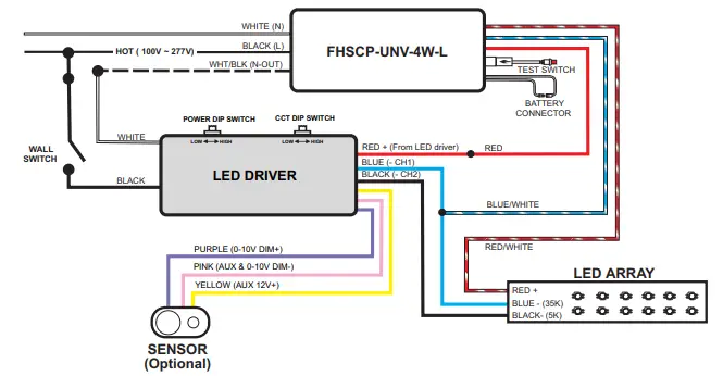
Wiring Diagram 2: 5000K Emergency Output
Additional Accessories (Sold Separately)
- Step 1 Locate and remove the sensor hole cover from the retrofit kit housing.
- Step 2 Remove the cable that is attached to the back of the sensor hole cover and insert the terminal into the PIR sensor
- Step 3 Insert the PIR sensor into the sensor hole on the retrofit kit housing and make sure its secured properly.
General Wiring Diagram
- Fulham Co. Inc.: 12705 South Van Ness Ave., Hawthorne, CA 90250 ·
- Telephone: 1-323-779-2980 ·
- Fax: 1-323-754-9060
- [email protected]
- www.fulham.com


