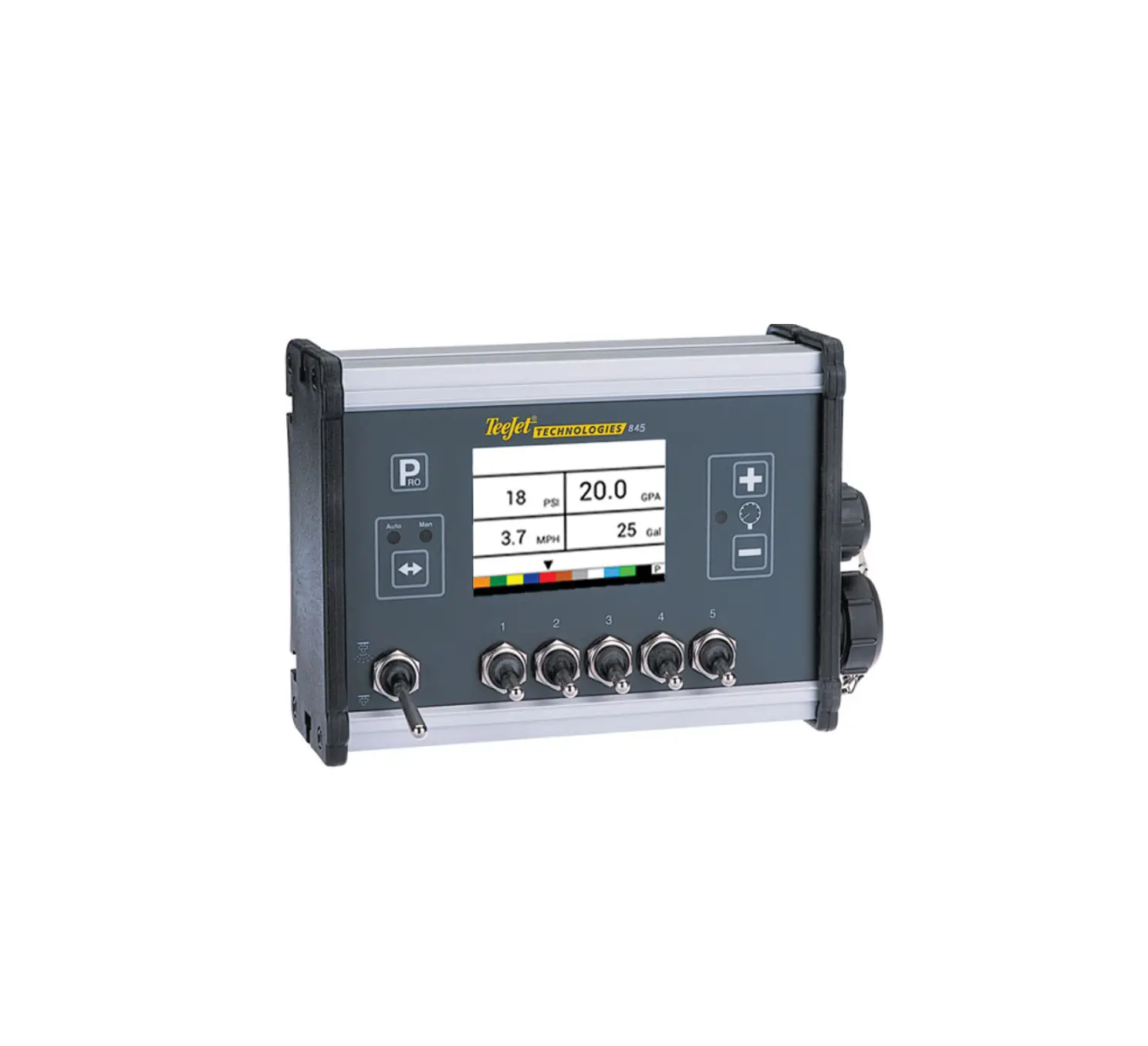
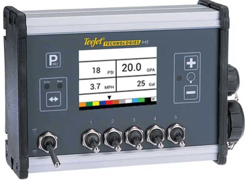
TeeJet 845 Sprayer Controller
POWER
Power On the Console
To power on the console:
- Press and release the PROGRAM
 button.
The console will initially display the software version at the top of the screen and the serial number of the console at the bottom of the screen. After approximately 3 seconds, the console will enter the work screen.
Power Off the Console
To power off the console:
1. While pressing and holding the MINUS ![]() button, press and release the PROGRAM
button, press and release the PROGRAM ![]() button.
button.
2. Release the MINUS ![]() button.
button.
The console will save new information (area and volume counters) to memory before it powers down. Pressing any key during the power off count down will cancel the shut off function.
Automatic Shutdown
With the Master Switch in the “OFF” position, the console will automatically shut down after 10 minutes of no inputs (or at the time specified in the Automatic Shutdown Time setting in the OEM Setup Mode)
SYSTEM SETUP MODE
Enter the System Setup Mode
The Master Switch must be off.
Press and hold the PROGRAM ![]() button until the Program System Menu screen appears (approximately 3 seconds).
button until the Program System Menu screen appears (approximately 3 seconds).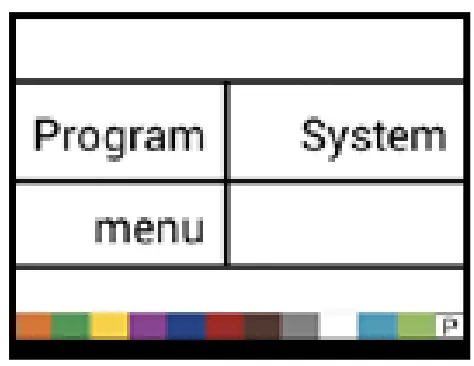
Advance to the Next Option
Press the PROGRAM ![]() button to advance the system to the next Program step. After the final setup op
button to advance the system to the next Program step. After the final setup op
Exit the System Setup Mode
Press and hold the PROGRAM ![]() button for 3 seconds.
button for 3 seconds.
The inputs are stored, and the console will exit the setup mode.
| Step | Display | Description | Default |
| Units | 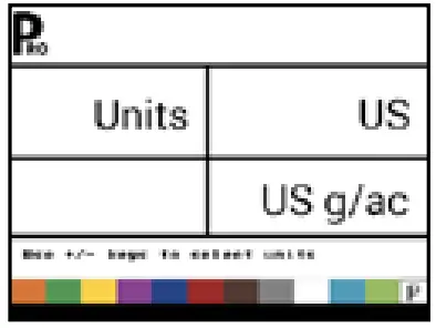 | Select the units for operation. Options include: US, SI, Turf, NH3, IMP, LM2, GLM, LKM. See the manual for unit details. | US |
| Restore Defaults | 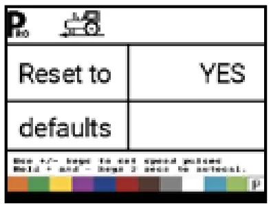 | f the units of measurement are changed, default values for all settings must be restored.
| Yes |
| Speed Sensor Calibration | 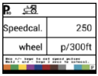 | Set number of Pulses per 300 feet/100 meters. While it is difficult to give an accurate starting value for a wheel speed sensor, radar (or simulated radar as with GPS speed) sources usually having a starting value. Make sure the source is set to “rad”.
| 250 pulses per 300 feet / 100 meters |
| Distance Counter | 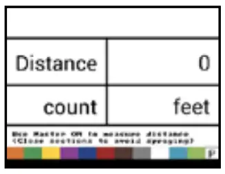 | The Distance Counter step is not a calibration step. It is a help function that can be used to measure a distance in feet/meters such as to confirm Automatic Speed Calibration. No value can be entered here. | 0 ft/ 0 m |
| Pressure Sensor Installed | 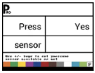 | Select if a pressure sensor is installed. If a flow sensor is not installed, this step is automatically set to “Yes” and cannot be changed. | Yes |
| Pressure Sensor-> Zero Pressure Reference | 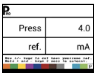 | This step is available if “Pressure Sensor Installed” is set to “Yes”. The Zero Pressure Reference is used to calibrate the zero pressure setting of the pressure sensor installed on the system. | 4.0 mA |
| Pressure Sensor-> Maximum Pressure Rating | 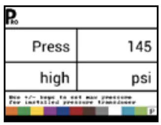 | This step is only available if “Pressure Sensor Installed” is set to “Yes” The Maximum Pressure Rating is used to establish the maximum rating of the pressure sensor in the system. This number can be found stamped on the pressure sensor itself. | 145 psi 10.0 bar |
| Minimum Pressure | 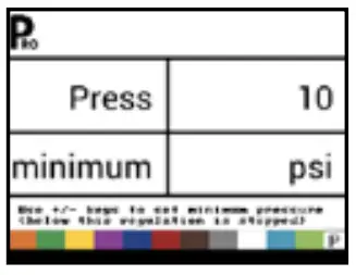 | Below the Minimum Pressure value, regulation is stopped, except when using lane spraying (GLM or LKM) | 10 psi 0.6 bar |
| Flow Meter Installed1 | 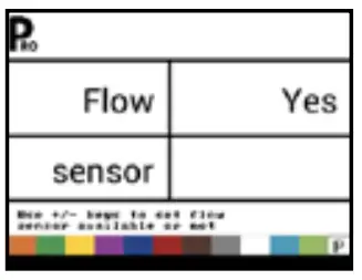 | Select if a flow meter is installed. | Yes |
| Flow Meter-> Flow Meter Calibration | 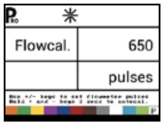 | This step is only available if “Flow Meter Installed” is set to “Yes”. Sets the number of pulses per liter. Pressing the AUTO/MAN button will switch between normal value and decimal value (/10). Most flow meters have a tag on the sensor cable which contains the proper flow meter calibration number and units used, whether pulses per gallon, pulses per liter, pulses per 10 gallons, etc.
| 650 pulses per liter |
| Flow Meter-> Flow Sensor Minimum Flow Capacity | 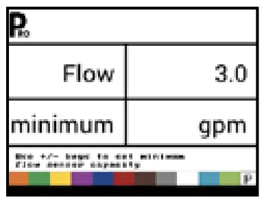 | This step is only available if “Flow Meter Installed” is set to “Yes” and the console is programmed for use with a pressure sensor Set the minimum flow capacity for the installed flow sensor. Below the minimum flow capacity, regulation will switch to pressure mode. When flow capacity once again reaches an acceptable level for the flow meter to regulate, the console automatically switches back to flow based regulation. | 3.0 gal/min 10.0 l/ min |
| Regulation Mode | 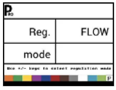 | This step is only available when both a Flow Meter and a Pressure Sensor are installed. This step is automatically set to “Flow” and cannot be changed if lane spraying is selected (GLM or LKM). Selecting a regulation mode will determine which sensor is used as the primary mode for regulation. | Flow |
| Tip/Nozzle Spacing | 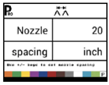 | Select the space between Tips/Nozzles. Spacing must match the physical spacing on the spraye | 20 in 50 cm |
| Number of Sections | 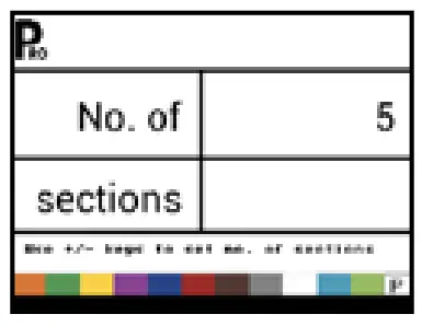 | Select the number of sections. The number of sections must match the physical number of sections on the sprayer. | 5 sections |
| Tips/Nozzles per Section | 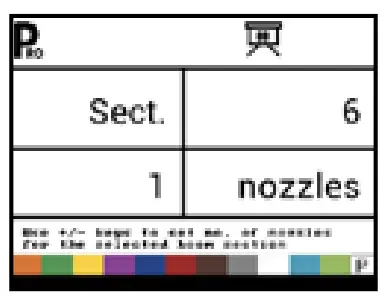 | Set number of Tips/Nozzles for each section. Each section programmed in the Number of Sections setting will have a separate setting to set the number of Tips/Nozzles per section. | 6 nozzles |
| Density | 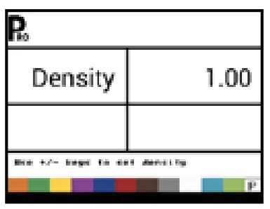 | Establishes the weight per volume setting based on the type of fertilizer being used. Water = 1.00. The density value equals Weight of the Solution ÷ Weight of Water. | 1.00 |
| Regulation Valve Typ | 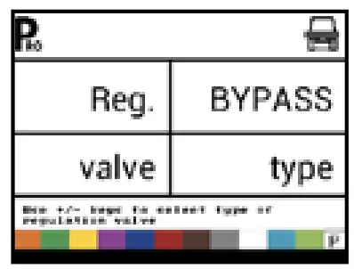 | Instructs the console where the regulating valve is plumbed into the system. Options include: Throttle, Bypass and PWM | Bypass |
| Regulation Speed Factor | 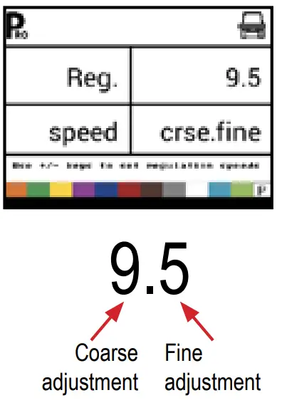 | The first digit sets the speed for the coarse adjustment in relation to a large percentage outside of the target application rate. The second digit sets the speed for the fine tune adjustment in relation to a small percentage close to the target application rate.
| Coarse: 9 Fine: 5 |
| Section Valve Type3 | 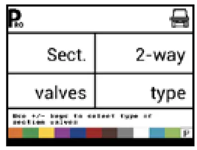 | The Section Valve Type distinguishes the type of On/Off boom control valves installed on the machine. | 2-way |
| Tank Size | 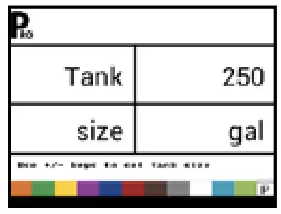 | Sets the maximum tank size. | 250 gallons 1000 liters |
| Minimum Tank Level | 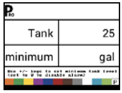 | Sets the tank level at which an alarm will trigger. Setting this value to 0 will disable the tank alarm. | 25 gallons 100 liters |
| Communication Mode | 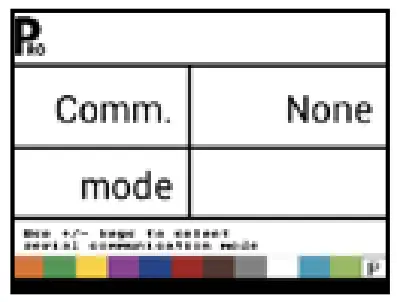 | The Communications step allows for the selection of the type of communications (if any) used. | None |
| Simulated Ground Speed – Low Speed | 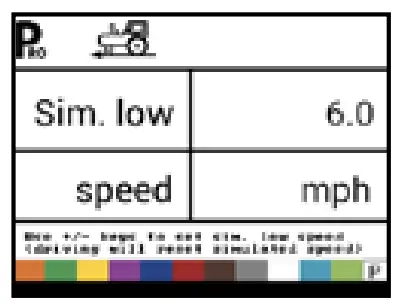 | Set simulated low speed. | 6.0 mph 10.0 km/h |
| Simulated Ground Speed – High Speed | 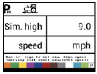 | Set simulated high speed. | 9.0 mph 15.0 km/h |
| Minimum Speed | 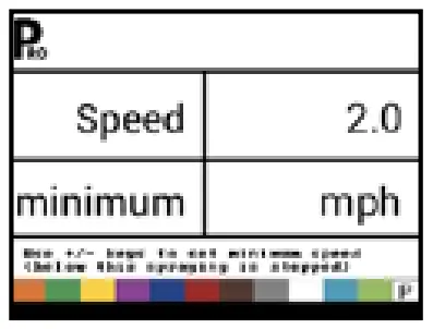 | Set the minimum speed at which the console automatically shuts the boom sections off to eliminate an operator function when slowing to stop or turn around. There will be no spraying below this speed. When the sprayer speed exceeds the established Auto Master Off Speed, the boom sections turn back on. Set this value to “0” to disable. | 2.0 mph 3.0 km/h |
APPLICATION SETUP MODE
The Application Setup Mode is used to set up application specific parameters.
Enter the Application Setup Mode
The Master Switch must be off.
Press and release the PROGRAM ![]() button once so the Program User Menu screen appears. Press and release the PROGRAM
button once so the Program User Menu screen appears. Press and release the PROGRAM ![]() button again within 3 seconds to enter the setting options.
button again within 3 seconds to enter the setting options.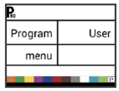
Advance to the Next Option
Press the PROGRAM ![]() button to advance the system to the next
button to advance the system to the next
Program step. After the final setup option is complete, the console return to the initial setup option.
Exit the System Setup Mode
Press and hold the PROGRAM ![]() button for 3 seconds.
button for 3 seconds.
The inputs are stored, and the console will exit the setup mode.
Activate Density Factor
At any time in Application Setup Mode, pressing the AUTO/MAN button will toggle the density symbol (‘D’) on or off. When the density symbol is on, the density value (set in System Setup mode) will be used in the regulation algorithms. If the density symbol is off, the density factor will not be used.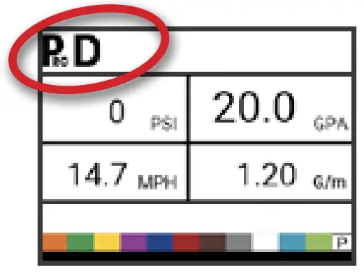
| Step | Display | Description | Defaults |
| Target Application Rate | | Set target application rate. | 20 gpa 200 l/ha |
| Known Pressure Value4 |  | The console will calculate the speed for the selected pressure, Tip/Nozzle type and target rate. X If the indicated speed is too high, a set of smaller Tips/ Nozzles is required. X If the indicated speed is too low, a set of larger Tips/ Nozzles is required. | 40 psi 2.0 bar |
| Known Speed Calculation5 |  | The console will calculate what the pressure must be to maintain the target application rate at the entered speed. | No defaul value |
| Programmable Tip/Nozzle Reference Flow6 |  | This step is only available if programmable Tip/Nozzle (‘P’) has been selected. Adjust reference flow at 40 psi / 2.75 bar for programmable Tip/ Nozzle. | 0.40 gal/min 1.29 l/min |
| Predefined Tip/Nozzle Selection7 | 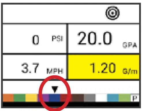 | The console will show the reference flow for the selected Tip/ Nozzle. | red tip/nozzle |
OPERATION FEATURES
| Feature and Display | Description |
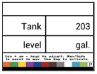
Tank Level | Used to show and/or set the actual content level in the tank. This level will decrease by the amount being sprayed. If the minimum tank level has been set to a value greater than zero and the actual level becomes less than the minimum level, a tank alarm will be triggered. Setting minimum tank level to zero will disable tank alarm function. View Tank Level – Start from the work screen with the Master Switch “OFF”.
|
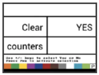
Clear Counters | Used to reset the total area, total volume and total distance counters to zero. Start from the work screen with the Master Switch “OFF”.
|
Simulated Speed | Allows the verification of console functions and the sprayer without actually moving the sprayer. Activate the Simulated Speed – While on the work screen without the machine in motion and the Master Switch in the “On” position:
Deactivate Simulated Speed – Once the sprayer begins moving and the console receives actual speed pulses, simulated ground speed is deactivated. Simulated speed will also be deactivated if the console is powered off. |
Manual/Automatic Regulation Mode | In manual mode, automatic rate regulation is stopped completely.
The valve (or the PWM duty cycle) stays in the position it had when the PLUS |
Boost Function | Used to increase or decrease the application rate by increments of 10%. Increase/Decrease Target Application Rate
|
ALARM SYSTEM
A number of sensor alarms have been included in the 845 software. The alarm system is only active with Master on. All audible alarm signals can be cancelled by pressing any button. All alarms are reset when Master is switched off.
| Alarm Name | Display | Description | Audible Alarm Type |
| Rate Alarm |  | Too high difference between target and actual rate. | High Priority (3 short beeps, repeated every second) |
| No Speed Alarm |  | If speed is zero with master on, then no speed alarm is triggered and spraying is stopped. | Medium Priority (2 short beeps, repeated every second) |
| No Flow Alarm | 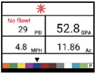 | If no flow pulses are received with master on and flow meter installed, a no flow alarm is triggered. | Medium Priority (2 short beeps, repeated every second). |
| No Pressure Alarm | 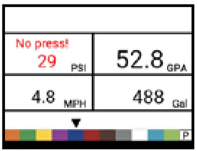 | If no pressure is measured with master on and pressure sensor installed, a no pressure alarm is triggered. | Medium Priority (2 short beeps, repeated every second). |
| Low Pressure Alarm | 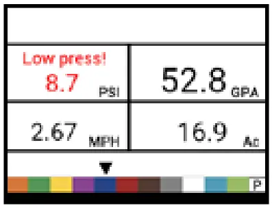 | If pressure drops below minimum value with master on, a low-pressure alarm is triggered. | Medium Priority (2 short beeps, repeated every second). |
| Low Speed Alarm | 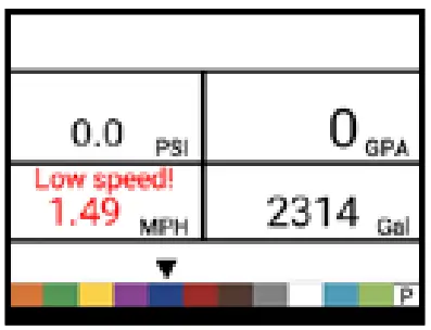 | If speed drops below minimum value with master on, a low-speed alarm is triggered and spraying is stopped. | Medium Priority (2 short beeps, repeated every second). |
| Pressure Difference Warning |  | With flow based regulation, the controller (if pressure sensor installed) will compare the actual measured pressure with the calculated pressure (based on flow and nozzle type). | No audible alarm. |
| Flow Difference Warning | 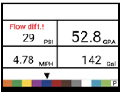 | With pressure based regulation, the controller (if flow meter installed) will compare the actual measured flow with the calculated flow (based on pressure and nozzle type). | No audible alarm. |
| Tank Level Alarm | 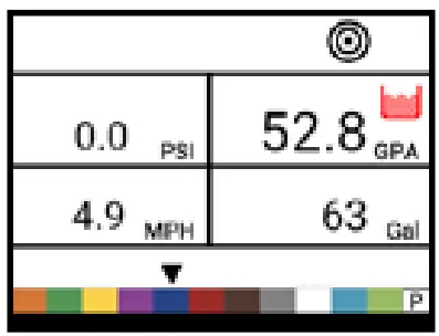 | Current tank level drops below tank minimum. | Low Priority (1 short beep, repeat every second). |
www.teejet.com
98-01609-ENUS A4LT R0 English-US
© TeeJet Technologies 2022