UNBRANDED Z-S07-P 500-Watt Electric Bike Fat Tire Instruction Manual
Product Description
| Frame | 6061 aluminum alloy | Battery | 36V 12.5Ah lithium battery |
| Motor | SOOW Rear brushless hub motor TRUCK | Controller | 36V 22A |
| Charge Time | 4-6 hours | Max Speed | 45 km/h |
| Range Distance | 25-35 km | Brake | F/R disc brake |
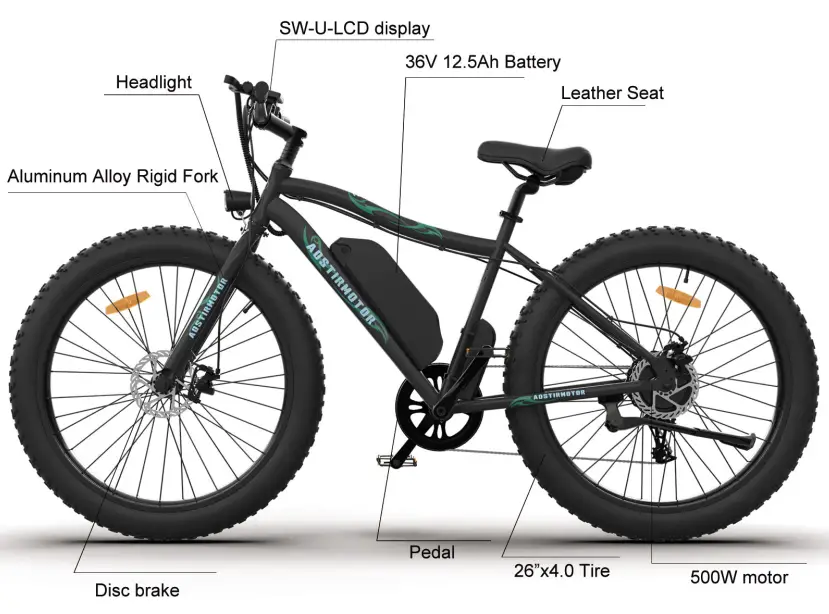
| Light | F:Light | Display | SW-U-LCD display |
| Fork | Aluminum Alloy Rigid Fork | Tire | 26×4.0 |
| Derailleur | Outer 7 speed SHIMANO | Packing Size | 158”28“85cm |
Safety Notice
To Ensure Your Safety, Make the Following Functional Checks Before Driving:
- Test brake system, throttle, and power system.
- Tire pressure should be at 30 psi.
- Check front wheel Iug-nuts, securely tighten before every ride.
- Battery charge level- found on side of battery.
- Braking system adjustment and free operation
Installation Instruction
- Open your package.
- Take out the tool box.
- Take out the bicycle from the package and put it on a soft surface to avoid scratches. Cut the tie that secures the front wheel to the side
- Remove the protective foam.
- Open the accessory kit and remove the tool kit
- Invert the bicycle.
- Remove the large fixing bolt on the front fork.
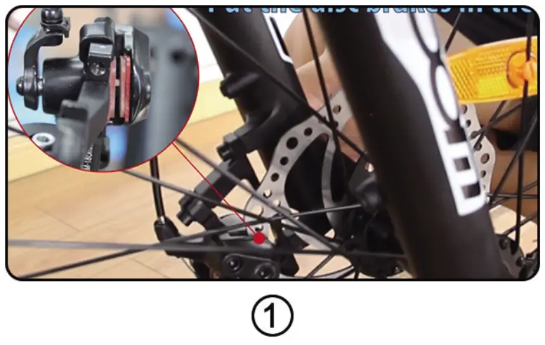
- Put the front wheel on the front fork and place the disc brake pad on the front wheel in the middle of the disc brake caliper( Figure 1).

- Use the supplied 15mm flat tool to tighten the two bolts.
- Tie the key to the handlebar clamp, cut the zipper, and then use the Allen wrench in the tool kit to remove the clamp.
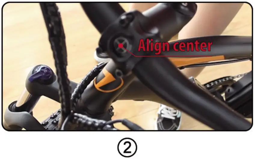
- Place the handlebar in the middle position (Figure 2), install the rod clamp and tighten the screws with the included Allen wrench.

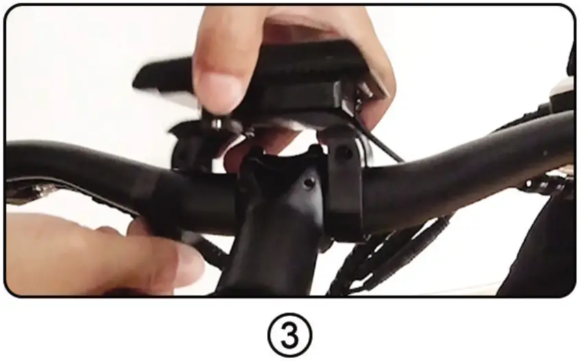
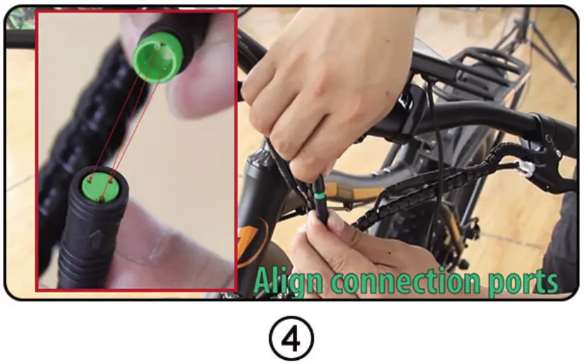
- Install the LCD-display on the handlebar (Figure 3), tighten the screws, and connect the green connecting wire (Figure 4)
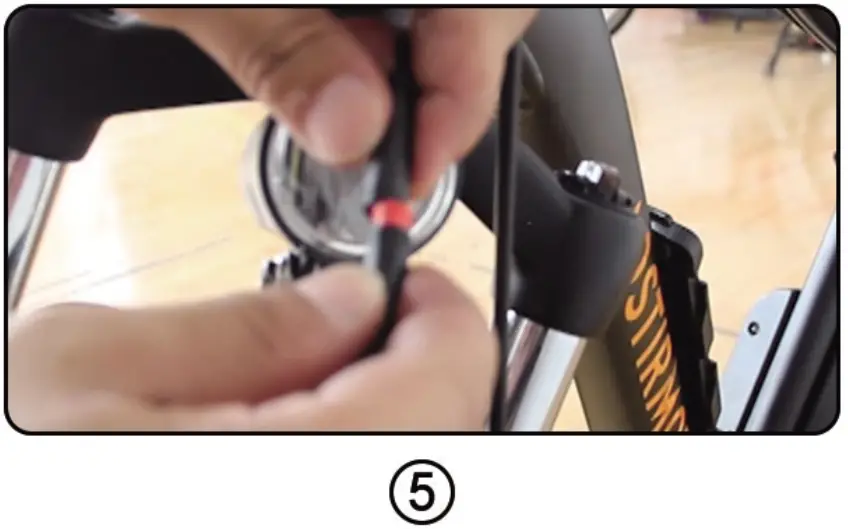
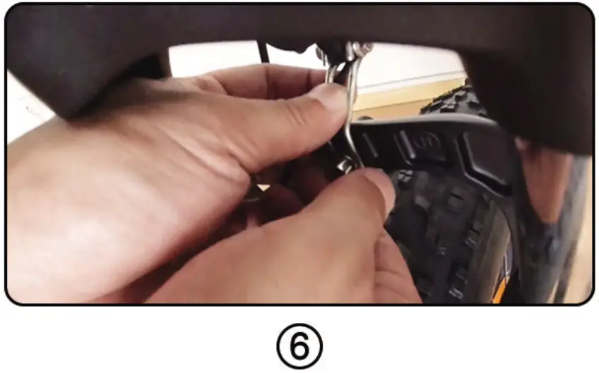
- Grasp the bicycle light and unscrew the lens. Then, remove the plastic insulator, re-tighten the lens, and then connect the red cable (Figure 5), and connect the bicycle
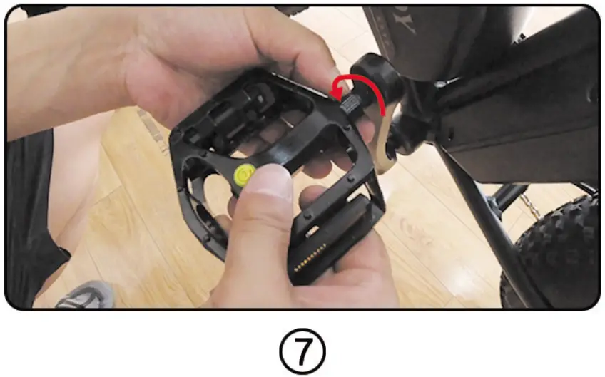
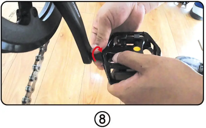
light to the screw above the front fork (Figure 6). - Install the pedal. The right pedal rotates clockwise (Figure 7), and the left pedal rotates counterclockwise (Figure 8).
NOTE: Pedal mark “L” means left and “R” means right. - Vertical bicycle
- Push the seat into the column, fix it in the desired position, tighten the screws, and then fix it.
- Installation is complete. When connecting meters, headlights, brake circuit breakers, handlebars, etc., please align them and do not install violently(Figure 4).
Battery Installation and Maintenance
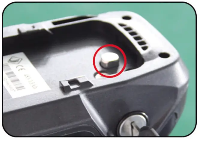
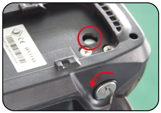
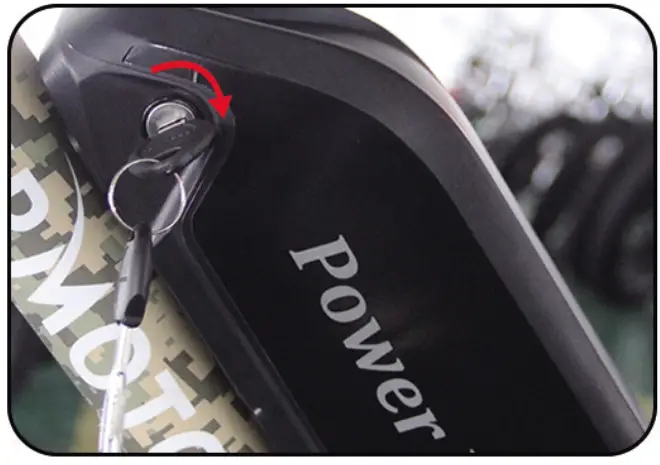
- Please check the situation of the lock core before installation, Step 2 and Step 3 for details.

- Turn your key counterclockwise to make the lock cylinder downward.
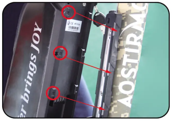
- As shown in the left picture, align the slider
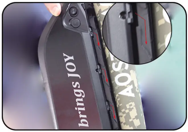
- Install along the buckle

- Battery installation complete
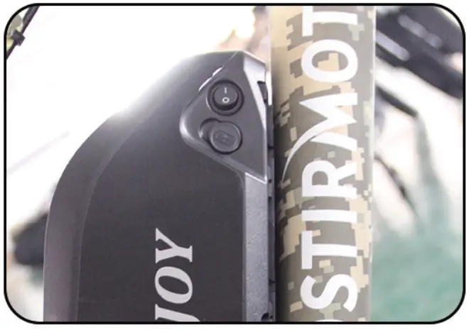
- Turn on the switch and the battery is powered
- When not using the battery for a long time, please charge it 1-2 times every month.
- Please keep the key properly. If your key is lost, we can provide a new key according to the nameplate number on the key
- Please keep the battery environment dry, for example, do not stay in the rain for a long time
- Please use a universal meter to test the battery attenuation regularly