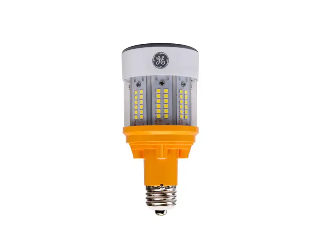
GE Appliances Type B LED HID Hazardous Rated Lamp 120-277V and 277-480V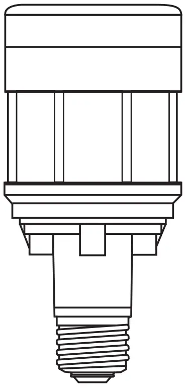
INTRODUCTION
BEFORE YOU BEGIN
Read these instructions completely and carefully.
Save these instructions for future use.
CONTACT A QUALIFIED ELECTRICIAN if you are not knowledgeable about luminaires and electrical systems. This LED
Retrofit Kit Installation requires a familiarity with safety procedures, if not qualified, do not attempt installation.
![]() WARNING
WARNING
Risk of electrical shock or fire. Before installing this kit in a luminaire, make sure the luminaire matches the features and dimensions indicated in the photographs and that the input rating of the retrofit kit does not exceed the input rating of the luminaire.
![]() WARNING
WARNING
DO NOT MAKE OR ALTER ANY OPEN HOLES IN AN ENCLOSURE OF WIRING OR ELECTRICAL COMPONENTS DURING KIT INSTALLATION.
Do not expose wiring to edges of sheet metal or other sharp objects to prevent wiring damage or abrasion.
DO NOT disconnect the existing wires from lamp holder terminals in preparation for new connections. Cut the existing lamp holder terminal wires an appropriate distance from the connection point and use applicable connectors to attach the new wires.
THE RETROFIT KIT IS ACCEPTED AS A COMPONENT OF A LUMINAIRE WHERE THE SUITABILITY OF THE COMBINATION SHALL BE DETERMINED BY AUTHORITIES HAVING JURISDICTION. PRODUCT MUST BE INSTALLED BY A QUALIFIED ELECTRICIAN IN ACCORDANCE WITH THE APPLICABLE AND APPROPRIATE ELECTRICAL CODES. THE INSTALLATION GUIDE DOES NOT SUPERSEDE LOCAL OR NATIONAL REGULATIONS FOR ELECTRICAL INSTALLATIONS. ENSURE CURRENTLY INSTALLED LUMINAIRE AND RETROFIT KITS ARE ONLY INSTALLED IN THE SAME HAZARDOUS (CLASSIFIED) LOCATIONS SPECIFIED ON THE RETROFIT KIT MARKING LABEL.
Input Rating
LED80ED23.5/YXX/HAZ 120-277V, 0.74 amps max, 80W
LED50ED23.5/YXX/HAZ 120-277V, 0.46 amps max, 50W
LED80ED23.5/YXX/HAZ 277-480V, 0.32 amps max, 80W
LED50ED23.5/YXX/HAZ 277-480V, 0.20 amps max, 50W
The Kit Includes:
- LED lamp
- Label for modified luminaire
- Installation instructions
- Wire connectors (2)
- E26 to E39 socket adapter, only included with 120-277V models
Luminaire Fittings Reference Table
| Luminaire Fitting | Page |
| GE Lighting Filtr-Gard® | 2 |
| Crouse-Hinds Champ® VMV | 3 |
| Appleton Mercmaster® III | 4 |
| Appleton Mercmaster® II | 5 |
| GE Lighting Powr-Gard® H9 Series | 6 |
| Hubbell Killark® VM Series | 7 |
| Holophane Petrolux P3M® | 9 |
| Thomas & Betts Hazlux® 3 Series | 10 |
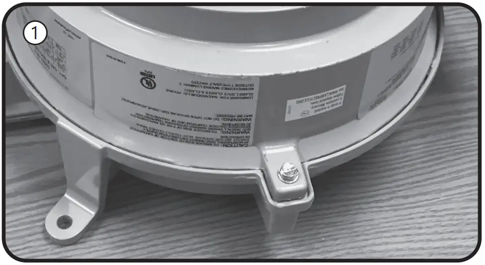
A Retrofitting GE Lighting Filtr-Gard®
Instructions for retrofitting UL Listed GE Lighting Filtr-Gard® Luminaire Fitting/Ballast Housing marked for use in Class I, Division 2, Groups A,B,C and D hazardous locations.
| Fitting | Filtr-Gard® Catalog# |
| Ballast Housing | Series H2 ballast housings |
| Cover/Mounting | Series H2000 mounts |
| Optical Assemblies | FG, FN, R2G, R5G, A2G, A5G,V2G, V5G, L2G, L5G |
| Lamp Base Adapter Usage for 120-277V models | |
| Housing | Adapter utilization |
| H2*0 SK, H2*05L, H2* 10M | Remove adapter from the lamp |
| All others | Use supplied adapter |
Tools needed:
- Slotted screwdriver and adjustable wrench
- Wire cutter
- Wire stripper
NOTE: The luminaire does not need to be removed from the mounting surface prior to modification
Instructions for GE Filtr-Gard® luminaire LED lamp and bypass ballast retrofit
Bypass Ballast Wiring
![]() WARNING
WARNING
Disconnect electrical power to the luminaire at the supply source.
![]() CAUTION
CAUTION
Avoid burn risk — allow luminaire and lamp to cool before proceeding.

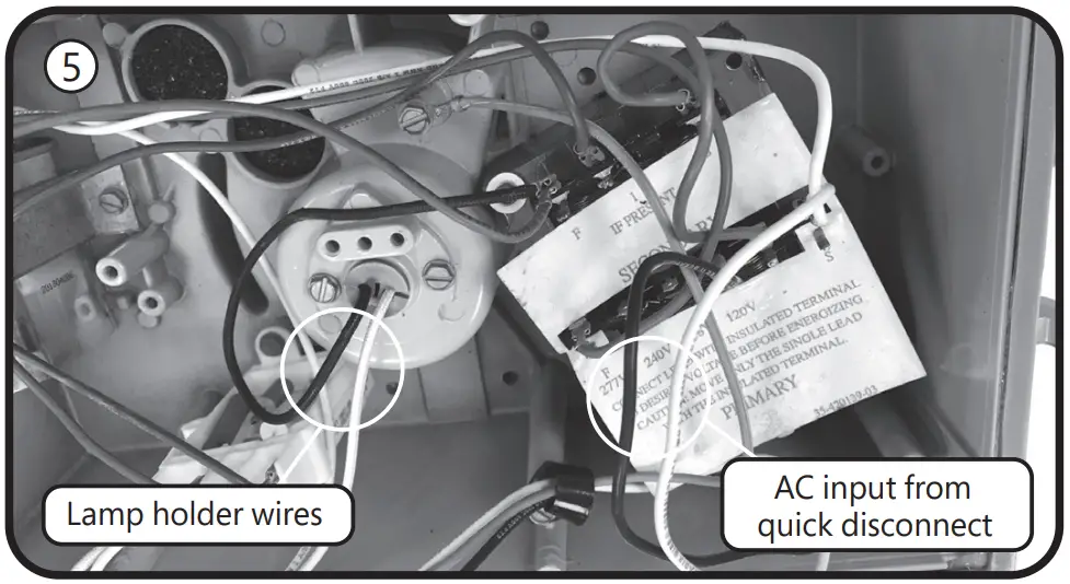
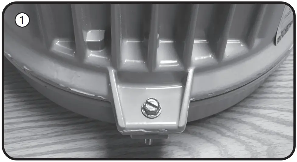
Loosen the screw that holds the ballast housing and cover together.- Hinge open the ballast cover and pull apart the two black plastic connectors to separate the quick disconnect function located between the cover and housing.
- Cut the black and white wires from the quick disconnect to the ballast circuitry leaving as much wire attached to the quick disconnect as possible. Be careful to leave the green ground wire connected.
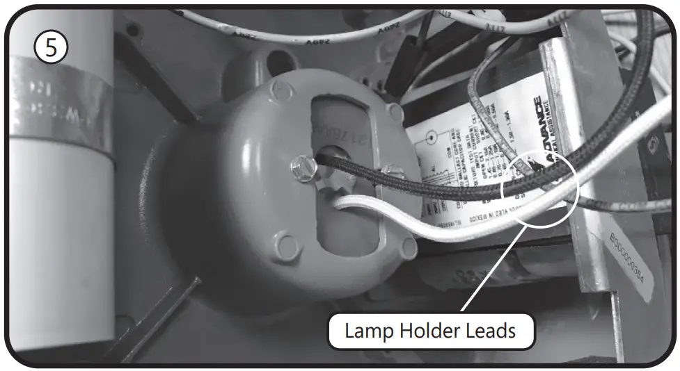
- Cut the white (neutral) and color (hot) wires from the lamp holder in the center of the ballast housing, leaving as much wire attached to the lamp holder as possible.
Strip 3/8 inch from the snipped quick disconnect wires (from step 3) and the snipped lamp holder wires (from step 4). Using the included wire connectors, connect white to white and black to color (may be black).- Place the ballast housing hinge pin over the cover hinge.
Reconnect the mains quick disconnect device. Ensure no wires are pinched when tightening the cover screw.
Filtr-Guard® is a registered trademark of General Electric Company
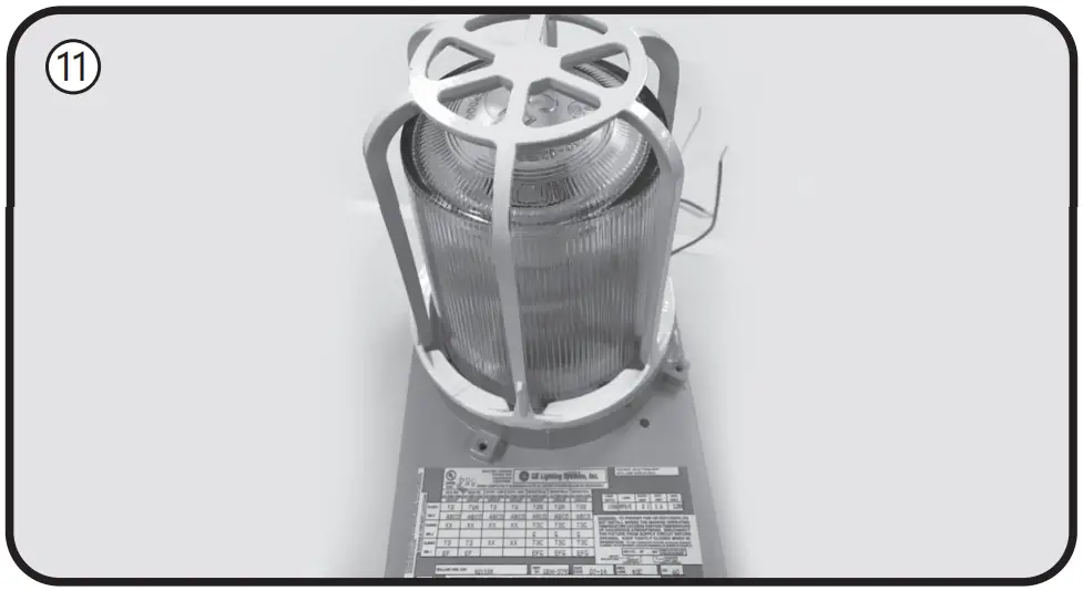
Lamp Installation Instructions - If there is an optical guard, remove by rotating counter-clockwise, or removing retaining screws.
- Remove the optical by gently turning in a counter-clockwise direction.
- Remove old HID lamp and inspect socket for signs of wear and/or arcing. Contact original luminaire manufacturer for replacement parts if needed.
- If the old lamp has an E39 mogul base, install lamp with the supplied E26 to E39 adapter into the luminaire socket. If the luminaire has an E26 socket, remove the adapter from the lamp. Refer to the Lamp Base Adapter Usage Table.
Install the new LED lamp, ensuring the lamp is properly seated.- Reinstall the optical and guard to their original positions.
- Apply the new ratings label over the existing luminaire label.
- The new label specifies the replacement lamp and the revised luminaire application ratings.
- Restore power to the luminaire.

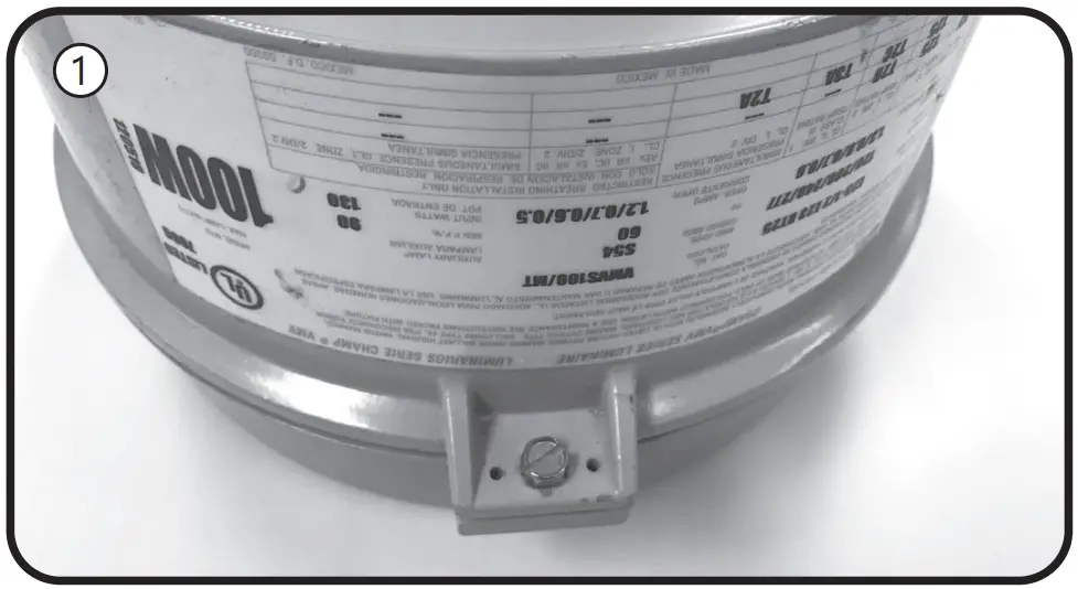
B Retrofitting Crouse-Hinds Champ®
Instructions for retrofitting UL Listed Crouse-Hinds Champ® VMV Series HID Luminaire Fitting/Ballast Housing marked for use in Class I, Division 2, Groups A,B,C and D hazardous locations
| Fitting | Champ® Catalog# |
| Ballast Housing | VMVS &VMVM |
| Champ Cover (Mounting Module) | APM2, APM3, HPM2, CM2, CM3, TWM2, TWM3, JM5, PM5, QM25 |
| Optical & Guard Components | G241,G243,G245,P241,R2,R3,R5,P23,PR2, PR3,PR5,RD70,RA70 |
| Lamp Base Adapter Usage for 120-277V models | |
| Ballast Housing | Adapter utilization |
| VMV5050, VMVM070, VMVM100 | Remove adapter from the lamp |
| All others | Use supplied adapter |
Tools needed:
- Slotted screwdriver and adjustable wrench
- Wire cutter
- Wire stripper
NOTE: The luminaire does not need to be removed from the mounting surface prior to modification
![]() WARNING
WARNING
Disconnect electrical power to the luminaire at the supply source.
![]() CAUTION
CAUTION
Avoid burn risk — allow luminaire and lamp to cool before proceeding.
Wiring
- Loosen the screw that holds the ballast housing and cover together.
- Hinge open the ballast cover.
- Remove wire connectors between incoming wires and ballast circuitry. Be careful to leave the green ground wire connected.
- Remove wire connectors from the lamp holder wires.
- Connect the lamp holder wires to incoming wires, using the included wire connectors. Connect white to white and black to black.
- Place the ballast housing hinge pin over the cover hinge.
Close and secure the ballast housing and cover by tightening the screw. Ensure no wires are pinched when closing luminaire.
Champ® is a registered trademark of Eaton’s Crouse-Hinds
Lamp Installation Instructions - Unthread the optical assembly to remove guards, globes, orexternal reflectors.
- Remove old HID lamp and inspect socket for signs of wear and/or arcing. Contact original luminaire manufacturer for replacement parts if needed.
- If the old lamp has an E39 mogul base, install lamp with the supplied E26 to E39 adapter into the luminaire socket. If the luminaire has an E26 socket, remove the adapter from the lamp. Refer to the Lamp Base Adapter Usage Table.
- Install the new LED lamp, ensuring the lamp is properly seated.
- Thread optical assembly into ballast housing.
- Apply the new ratings label over the existing luminaire label.
The new label specifies the replacement lamp and the revised luminaire application ratings. - Restore power to the luminaire.
C Retrofitting Appleton Mercmaster®
Instructions for retrofitting UL Listed Appleton Mercmaster® III Series HID Luminaire Fitting/Ballast Housing marked for use in Class I, Division 2, Groups A,B,C and D hazardous locations.
| Fitting | Mercmaster® III Catalog# |
| Ballast Housing | MLBG, MLBR,KPB & KPBR |
| Mounting Hood | KPA75, KPA100, KPAF75, KPAF100, KPC75, KPC100, KPCH75, KPCH100, KPS125, KPS150, KPST125, KPST150, KPWB75, KPWN100 |
| Optical & Guard Components | CMR-4AN, CMR-45T, KR2-AN, KR2-ST, KRG2, KGU2, LPG-R*, LPRF-*CP, VPGL-*HR |
| Lamp Base Adapter Usage for 120-277V models | |
| Ballast Housing | Adapter utilization |
| MLBG & MLBR | Remove adapter from the lamp |
| KPB & KPBR | Use supplied adapter |
Tools needed:
- Slotted screwdriver and adjustable wrench
- Wire cutter
- Wire stripper
NOTE: The luminaire does not need to be removed from the mounting surface prior to modification
![]() WARNING
WARNING
Disconnect electrical power to the luminaire at the supply source.
![]() CAUTION
CAUTION
Avoid burn risk — allow luminaire and lamp to cool before proceeding.
Wiring
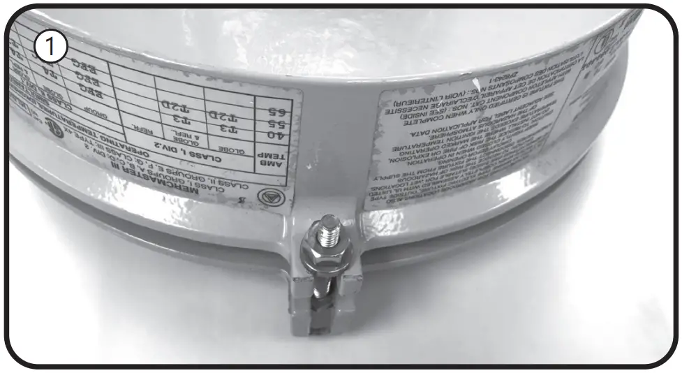
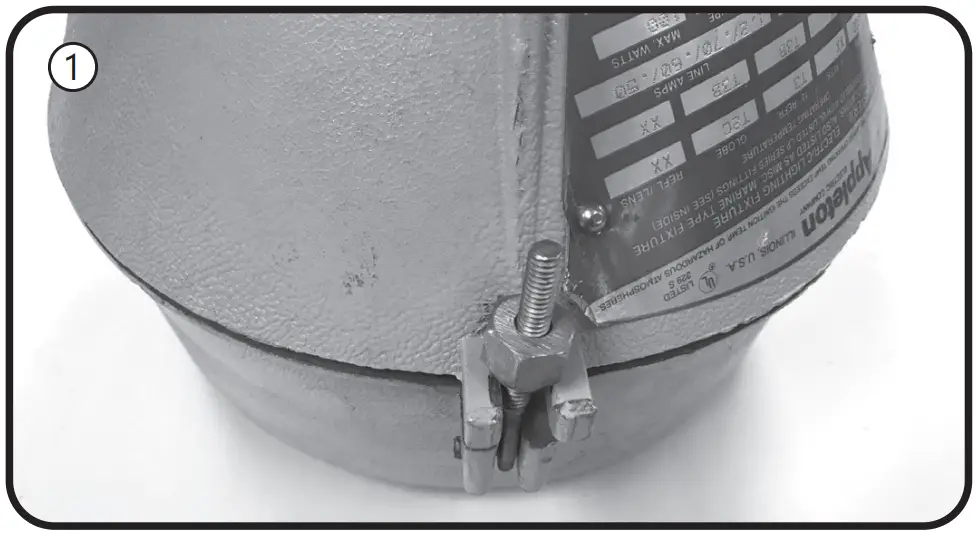
- Loosen the nut that holds the ballast housing and cover together.
- Hinge open the ballast cover.
- Remove wire connectors /wire nuts between incoming wires and ballast circuitry. Disconnect the incoming wire to the fuse if the device has one. Discard all the fuses if applicable. Be careful to leave the green ground wire connected.
- Remove wire connectors from the lamp holder wires, which may be bundled together with other wires. Carefully trace all wires from the lamp holder. Discard any additional white wires.
- Connect the lamp holder wires to incoming wires, using the included wire connectors. Make sure the supply neutral is connected to the white wire and the supply hot is connected to the lamp holder black wire.
- Place the ballast housing hinge pin over the cover hinge.
Close and secure the ballast housing and cover by tightening the screw.
Mercmaster® is a registered trademark of Appleton Grp.
Lamp Installation Instructions - Loosen screws and unthread the optical assembly to remove guards, globes, or external reflectors.
- Remove old HID lamp and inspect socket for signs of wear and/or arcing. Contact original luminaire manufacturer for replacement parts if needed
- .If the old lamp has an E39 mogul base, install lamp with the supplied E26 to E39 adapter into the luminaire socket. If the luminaire has an E26 socket, remove the adapter from the lamp. Refer to the Lamp Base Adapter Usage Table.
- Install the new LED lamp, ensuring the lamp is properly seated.
- Thread optical assembly into ballast housing.
- Apply the new ratings label over the existing luminaire label.
The new label specifies the replacement lamp and the revised luminaire application ratings. - Restore power to the luminaire.
D Retrofitting Appleton Mercmaster®
Instructions for retrofitting UL Listed Appleton Mercmaster® II Series HID Luminaire Fitting/Ballast Housing marked for use in Class I, Division 2, Groups A,B,C and D hazardous locations.
| Fitting | Mercmaster® II Catalog# |
| Ballast Housing | LPB, 4 ¾” height housing only |
| Mounting Hood | LPA-75, LPA-100, LPC-75, LPC-100, LPWB-75, LPWB-100, LPS-125, LPSD-150 |
| Optical & Guard Components | LPRF-***, VPGL-*****, KGU2, KR2-**, LPG-** |
| Lamp Base Adapter Usage for 120-277V models | |
| Ballast Housing | Adapter utilization |
| LPB, 4 ¾”height housing only | Use supplied adapter |
Tools needed:
- Slotted screwdriver and adjustable wrench
- Wire cutter
- Wire stripper
NOTE: The luminaire does not need to be removed from the mounting surface prior to modification
![]() WARNING
WARNING
Disconnect electrical power to the luminaire at the supply source.
![]() CAUTION
CAUTION
Avoid burn risk — allow luminaire and lamp to cool before proceeding.
Wiring
- Loosen the nut that holds the ballast housing and cover together.
- Hinge open the ballast cover.
- Remove wire connectors /wire nuts between incoming wires and ballast circuitry. Be careful to leave the green ground wire connected.
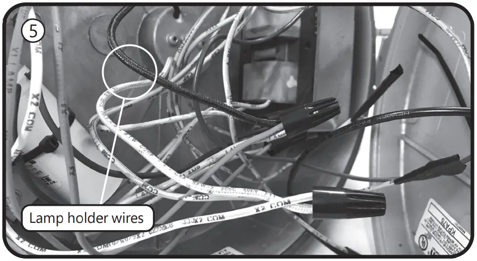
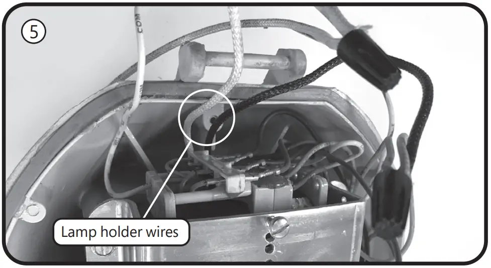
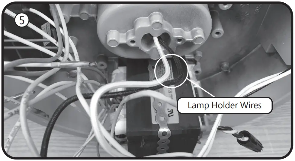
- Locate the wire tie and cut it, separate the wiring from the
bundle. Remove wire connectors from the lamp holder wires.
Discard any additional white wires. The lamp holder wires are
black and white and come from under the ballast housing.
The ballast is under the bracket in the center of the housing. - Connect the lamp holder wires to incoming wires, using the included wire connectors. Make sure the supply neutral is connected to the white wire and the supply hot is connected to the lamp holder black wire.
- Place the ballast housing hinge pin over the cover hinge.
Close and secure the ballast housing and cover by tightening the nut.
Mercmaster® is a registered trademark of Appleton Grp.
Lamp Installation Instructions - Loosen screws and unthread the optical assembly to remove guards, globes, or external reflectors.
- Remove old HID lamp and inspect socket for signs of wear and/or arcing. Contact original luminaire manufacturer for replacement parts if needed.
- If the old lamp has an E39 mogul base, install lamp with the supplied E26 to E39 adapter into the luminaire socket. If the luminaire has an E26 socket, remove the adapter from the lamp. Refer to the Lamp Base Adapter Usage Table.
- Install the new LED lamp, ensuring the lamp is properly seated.
- Thread optical assembly into ballast housing.
- Apply the new ratings label over the existing luminaire label.
The new label specifies the replacement lamp and the revised luminaire application ratings. - Restore power to the luminaire.
E Retrofitting GE Lighting Powr-Gard®
Instructions for retrofitting UL Listed GE Lighting Powr-Gard® Luminaire Fitting/Ballast Housing marked for use in Class I, Division 2, Groups A,B,C and D hazardous locations.
| Fitting | Powr-Gard® Catalog# |
| Ballast Housing | Series H9 ballast housings |
| Cover/Mounting | Series H9 mounts |
| Optical & Guard Components | JJ, JN, H9000-001, H9000-002, H9000-006 |
| Lamp Base Adapter Usage for 120-277V models | |
| Ballast Housing | Adapter utilization |
| H9 | Use supplied adapter |
Tools needed:
- Slotted screwdriver
- Small flat blade screwdriver
- Wire cutter
- Wire stripper
NOTE: The luminaire does not need to be removed from the mounting surface prior to modification
Instructions for GE Powr-Gard® luminaire LED lamp and bypass ballast retrofit
Bypass Ballast Wiring
![]() WARNING
WARNING
Disconnect electrical power to the luminaire at the supply source.
![]() CAUTION
CAUTION
Avoid burn risk — allow luminaire and lamp to cool before proceeding.
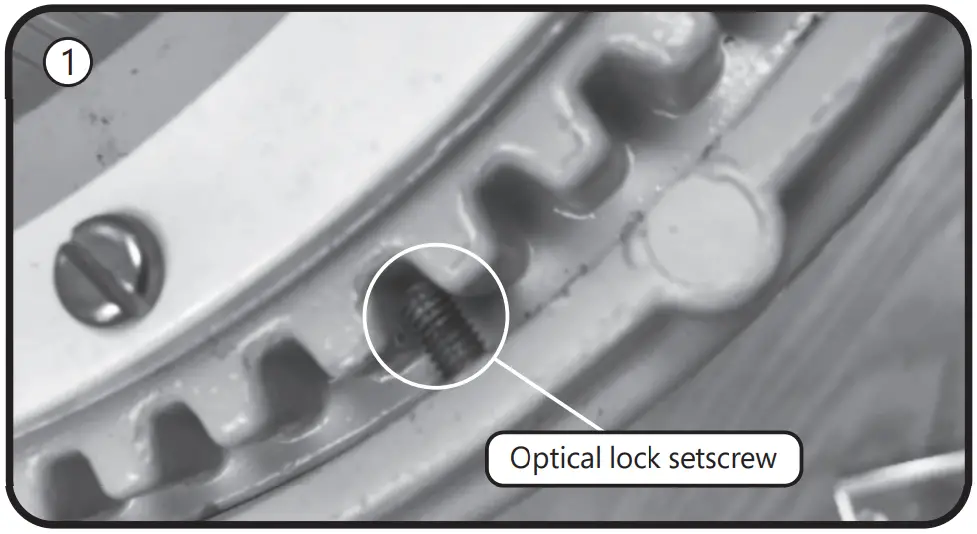
- Loosen the setscrew with a small flat blade screwdriver and remove the optical assembly by rotataing counterclockwise.
- Remove old HID lamp and inspect socket for signs of wear and/or arcing. Contact original luminaire manufacturer for replacement parts if needed.
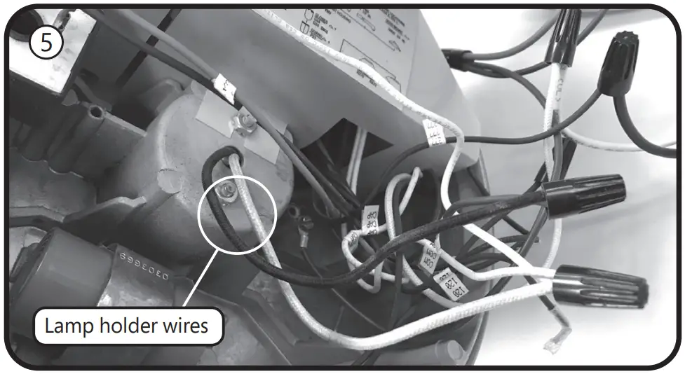
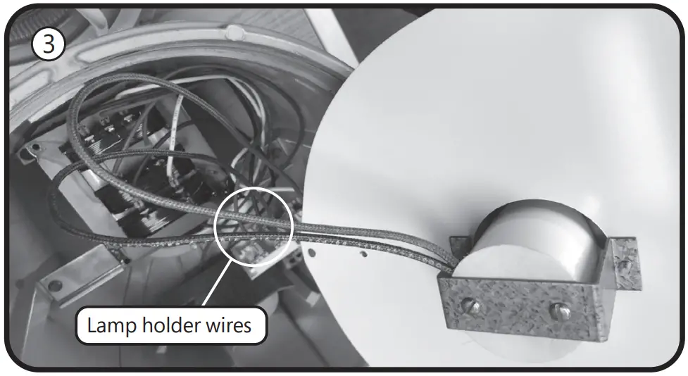
- Remove ballast cover plate. Locate wires going to lamp socket, and disconnect from the ballast. Cut and remove terminations, keeping lampholder wires as long as possible.
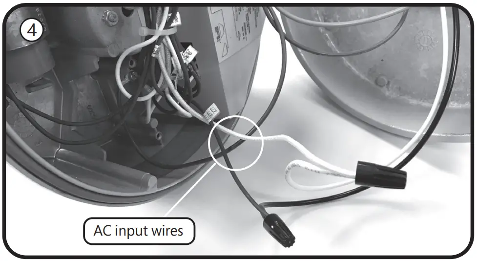
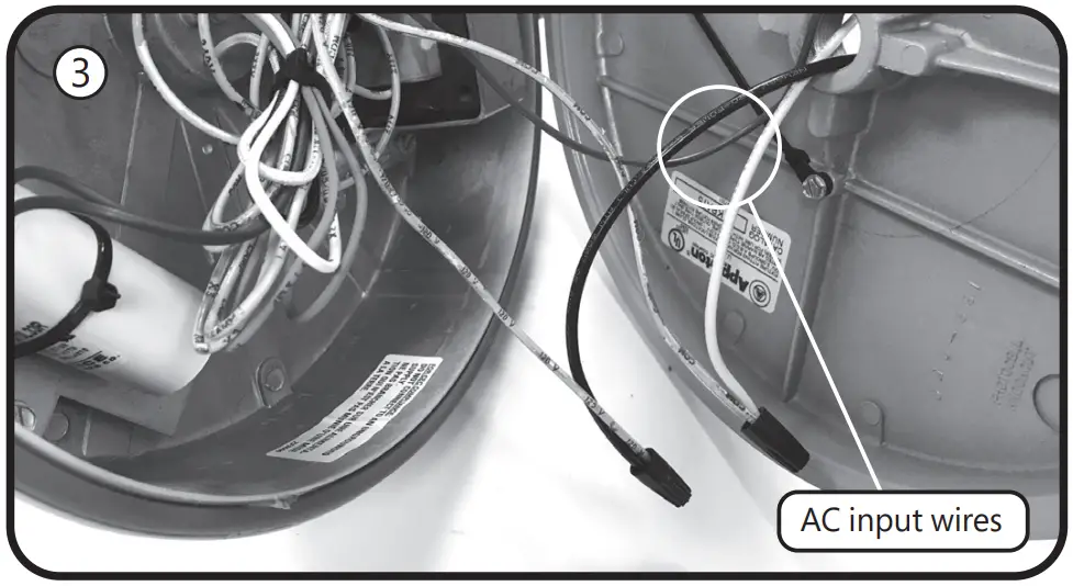
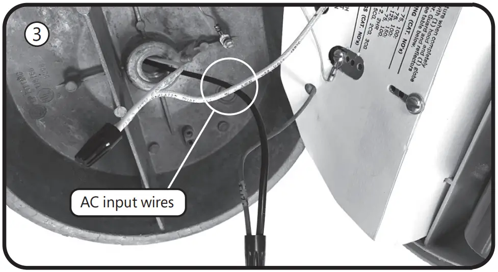
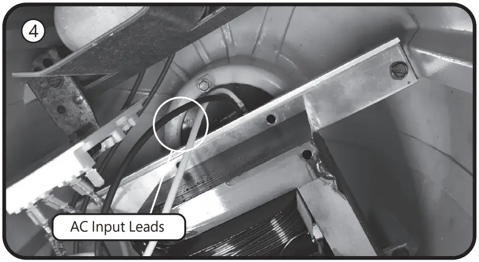
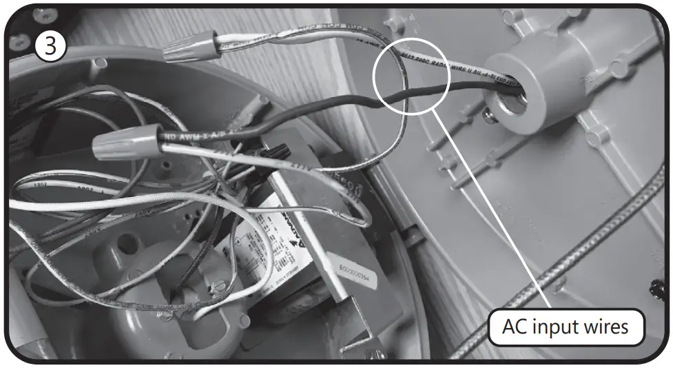
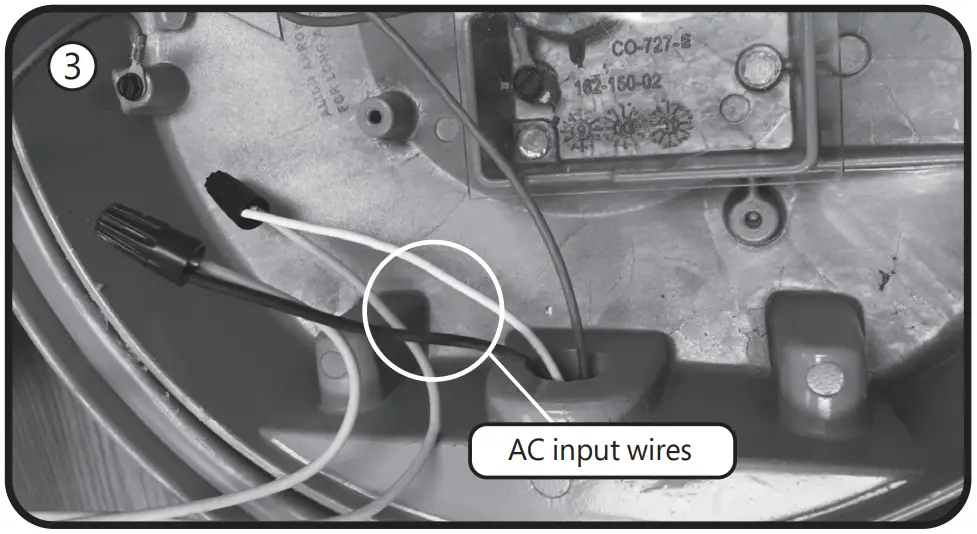
- Disconnect the AC input wires from the ballast and cut and remove the terminations, keeping the wires as long as possible.
- Strip 3/8 inch from the snipped lamp holder wires (from step 3) and the snipped AC input wires (from step 4). Using the included wire connectors, connect the AC to the lamp holder wires as follows: If the lamp holder wires are white and black, then connect white to white and black to black. If the lamp holder wires are black and blue, connect AC white to lamp holder blue, connect AC black to lamp holder black. If the lamp holder wires are white and blue, connect AC white to lamp holder white and AC black to lampholder blue.
- Reinstall the ballast cover plate and lamp holder. Ensure no wires are pinched when tightening the cover screws.
Lamp Installation Instructions - If the old lamp has an E39 mogul base, install lamp with the supplied E26 to E39 adapter into the luminaire socket. If the luminaire has an E26 socket, remove the adapter from the lamp. Refer to the Lamp Base Adapter Usage Table.
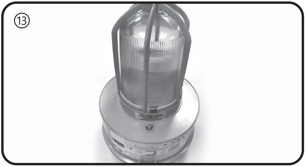
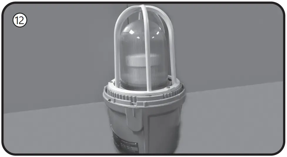
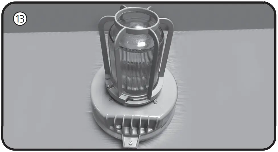
- Install the new LED lamp, ensuring the lamp is properly seated.
- Reinstall the optical (and guard) by rotating the optical assembly clockwise while supporting the optical.
- Retighten the optical lock setscrew with a small flat blade screwdriver.
- Apply the new ratings label over the existing luminaire label.
The new label specifies the replacement lamp and the revised luminaire application ratings.
Powr-Gard® is a registered trademark of General Electric Company - Restore power to the luminaire.
E Retrofitting Hubbell Killark®
Instructions for retrofitting UL Listed Hubbell Killark® VM Series HID Luminaire Fitting/Ballast Housing marked for use in Class I, Division 2, Groups A,B,C and D hazardous locations.
| Fitting | Killark® Catalog# |
| Ballast Housing | VM1, VM2, VM3, VM4, VM5, VMLO, VMMO |
| Cover (Mounting Module) | VMA2B, VMA3B, VMB2B, VMB3B, VMC2B, VMC3B, VMD4B, VMD5B, VMF2B, VMF3B, VMS4B, VMS5B, VMX2B, VMX3B, VMX6B, VMX7B, VMX8B, VMX9B |
| Optical & Guard Components | VMG25, VMR*, VZRG*, VMEP40, VMER40, VMAG25S, VMERG, VMRWG, VMRWG8, VMRERG, VMPSD40, VMPA40, VMG40 |
| Lamp Base Adapter Usage for 120-277V models | |
| Ballast Housing | Adapter utilization |
| VM1, VM2, | Remove adapter from the lamp |
| VM3, VM4, VM5, VMLO, VMMO | Use supplied adapter |
Tools needed:
- Slotted screwdriver and adjustable wrench
- Wire cutter
- Wire stripper
NOTE: The luminaire does not need to be removed from the mounting surface prior to modification
![]() WARNING
WARNING
Disconnect electrical power to the luminaire at the supply source.
![]() CAUTION
CAUTION
Avoid burn risk — allow luminaire and lamp to cool before proceeding.
Wiring
- Loosen the screw that holds the ballast housing and cover together.
- Hinge open the ballast cover.
- Remove wire connectors between incoming wires and ballast circuitry. Be careful to leave the green ground wire connected.
- Remove wire connectors from the lamp holder wires.
- Connect the lamp holder wires to incoming wires, using the included wire connectors. Connect white to white and black to black.
- Place the ballast housing hinge pin over the cover hinge.
Close and secure the ballast housing and cover by tightening the screw. Ensure no wires are pinched when closing fixture.
Lamp Installation Instructions - Unthread the optical assembly to remove guards, globes, or external reflectors.
- Remove old HID lamp and inspect socket for signs of wear and/or arcing. Contact original luminaire manufacturer for replacement parts if needed.
- If the old lamp has an E39 mogul base, install lamp with the supplied E26 to E39 adapter into the luminaire socket. If the luminaire has an E26 socket, remove the adapter from the lamp. Refer to the Lamp Base Adapter Usage Table.
- Install the new LED lamp, ensuring the lamp is properly seated.
- Thread optical assembly into ballast housing.
- Apply the new ratings label over the existing luminaire label.
The new label specifies the replacement lamp and the revised luminaire application ratings. - Restore power to the luminaire.
F Retrofitting Holophane Petrolux P3M®
Instructions for retrofitting UL Listed Holophane Petrolux P3M® Series HID Luminaire Fitting/Ballast Housing marked for use in Class I, Division 2, Groups A,B,C and D hazardous locations.
| Fitting | Holophane P3M® Refractor |
| Ballast Housing | HID Source, 50-175 watt HPS or MH |
| Mounting Hood | ST, WL, PD, CE, UN |
| Optical & Guard Components | 541, 545, GD |
| Lamp Base Adapter Usage for 120-277V models | |
| Ballast Housing | Adapter utilization |
| MH Source (E26 socket) | Remove adapter from the lamp |
| MH Source (E39 socket) HPS Source (E39 socket) | Use supplied adapter |
Tools needed:
- Slotted screwdriver and adjustable wrench
- Wire cutter
- Wire stripper
NOTE: The luminaire does not need to be removed from the mounting surface prior to modification
WARNING
Disconnect electrical power to the luminaire at the supply source.
CAUTION
Avoid burn risk — allow luminaire and lamp to cool before proceeding.
Wiring
- Loosen the bolt that holds the ballast housing and cover together.
- Hinge open the ballast cover.
- Remove wire connectors /wire nuts between incoming wires and ballast circuitry. Disconnect the incoming wire to the fuse if the device has one. Discard all the fuses if applicable. Be careful to leave the green ground wire connected.
- Remove wire connectors from the lamp holder wires, which
may be bundled together with other wires. Carefully trace all
wires from the lamp holder. Disconnect any additional wires
from the lamp holder white and black leads - Connect the lamp holder wires to incoming wires, using the included
wire connectors. Make sure the supply neutral is connected to the white
wire and the supply hot is connected to the lamp holder black wire. - Place the ballast housing hinge pin over the cover hinge.
Close and secure the ballast housing and cover by tightening the screw.
Lamp Installation Instructions - Remove optical assembly by turning black tabs around optical counterclockwise.
- Remove old HID lamp and inspect socket for signs of wear and/or arcing. Contact original luminaire manufacturer for replacement parts if needed.
- If the old lamp has an E39 mogul base, install lamp with the supplied E26 to E39 adapter into the luminaire socket. If the luminaire has an E26 socket, remove the adapter from the lamp. Refer to the Lamp Base Adapter Usage Table.
- Install the new LED lamp, ensuring the lamp is properly seated
- Thread optical assembly into ballast housing.
- Apply the new ratings label over the existing luminaire label. The new label specifies the replacement lamp and the revised luminaire application ratings.
- Restore power to the luminaire.

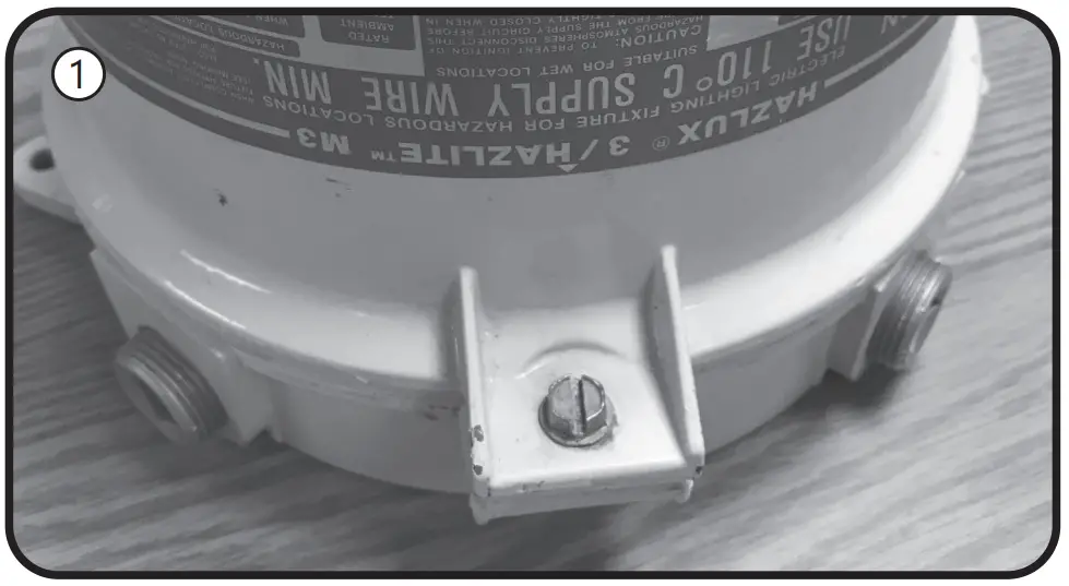
G Retrofitting Thomas & Betts Hazlux®
Instructions for retrofitting UL Listed Thomas & Betts Hazlux® 3 Series HID Luminaire Fitting/Ballast Housing marked for use in Class I, Division 2, Groups A,B,C and D hazardous locations.
| Fitting | Thomas & Betts Hazlux® Catalog# |
| Ballast Housing | DS, DH |
| Mounting Hood | VA2, VA3, VB2, VB3, VC2, VC3, VF2, VF3, VL4, VL5, VP2, VP3, VS4, VS5 |
| Optical & Guard Components | VGT31S, VGT31STS, VRF22C5, VRF31C5, VGL31R1, VGL31R3, VGL31R5, VRB31CBVGR48, VGR64, VGU31R, VGU31RP, VRA22P, VR22P, VR31P, VRA31P |
| Lamp Base Adapter Usage for 120-277V models | |
| Ballast Housing | Adapter utilization |
| MH Source (E26 socket) | Remove adapter from the lamp |
| MH Source (E39 socket) HPS Source (E39 socket) | Use supplied adapter |
Tools needed:
- Slotted screwdriver and adjustable wrench
- Wire cutter
- Wire stripper
NOTE: The luminaire does not need to be removed from the mounting surface prior to modification
![]() WARNING
WARNING
Disconnect electrical power to the luminaire at the supply source.
![]() CAUTION
CAUTION
Avoid burn risk — allow luminaire and lamp to cool before proceeding.
Wiring
- Loosen the bolt that holds the ballast housing and cover together.

- Hinge open the ballast cover.
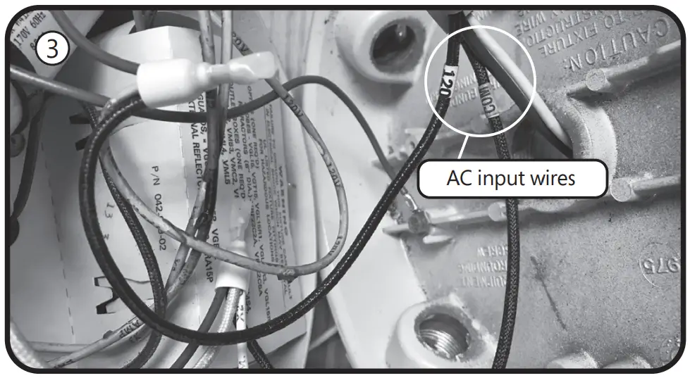
- Remove wire connectors /wire nuts between incoming wires and ballast circuitry. Disconnect the incoming wire to the fuse if the device has one. Discard all the fuses if applicable. Be careful to leave the green ground wire connected.
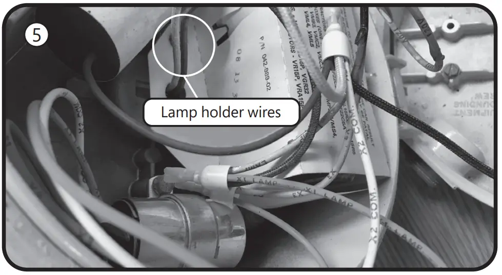
- Remove wire connectors from the lamp holder wires, which may be bundled together with other wires. Carefully trace all wires from the lamp holder. Disconnect any additional wires from the lamp holder white and black leads.
- Connect the lamp holder wires to incoming wires, using the included wire connectors. Make sure the supply neutral is connected to the white wire and the supply hot is connected to the lamp holder black wire.
- Place the ballast housing hinge pin over the cover hinge.
Close and secure the ballast housing and cover by tightening the screw.
Lamp Installation Instructions - Loosen screws and unthread the optical assembly to remove guards, globes, or external reflectors.
- Remove old HID lamp and inspect socket for signs of wear and/or arcing. Contact original luminaire manufacturer for replacement parts if needed.
- If the old lamp has an E39 mogul base, install lamp with the supplied E26 to E39 adapter into the luminaire socket. If the luminaire has an E26 socket, remove the adapter from the lamp. Refer to the Lamp Base Adapter Usage Table.
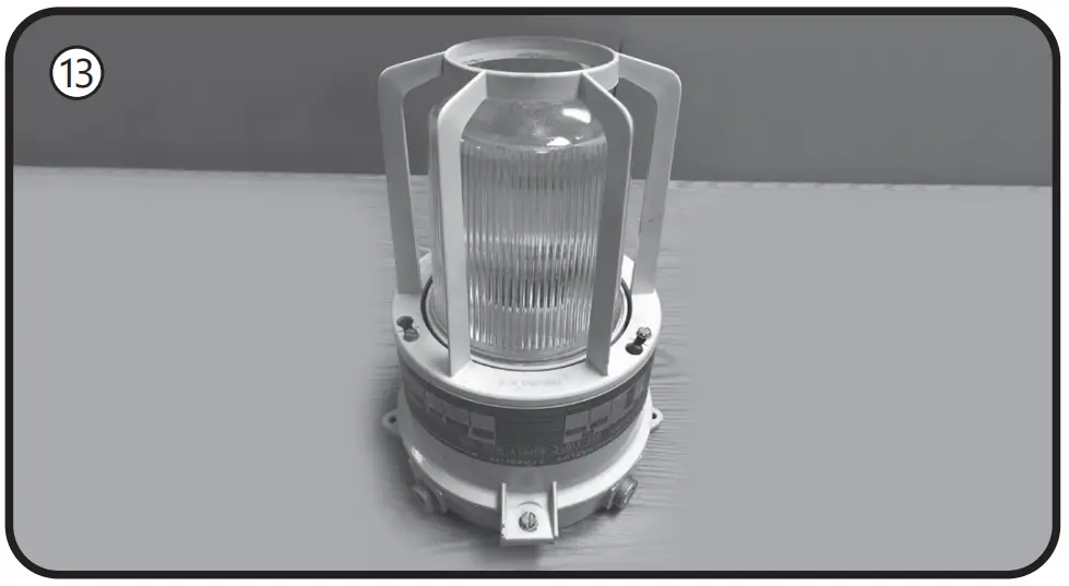
- Install the new LED lamp, ensuring the lamp is properly seated.
- Thread optical assembly into ballast housing.
- Apply the new ratings label over the existing luminaire label.
The new label specifies the replacement lamp and the revised luminaire application ratings. - Restore power to the luminaire.
These instructions do not purport to cover all details or variations in equipment nor to provide for every possible contingency to be met in connection with installation, operation or maintenance. Should further information be desired or should particular problems arise which are not covered sufficiently for the purchaser’s purposes, the matter should be referred to GE current, a Daintree company


 Installation Guide")

 Installation Guide")


