TSINGLINK DSJ-TSP26A1 4G Body Worn Camera
Thank you very much for purchasing our product. If you have any questions or needs, please feel free to contact us This manual is suitable for DSJ-TSP26A1 body worn camera. This manual may contain technical inaccuracies, inconsistencies with product functions and operations, or misprints. We will update the contents of this manual according to the enhancement of product functions, and will regularly improve or update the products or procedures described in this manual. The updated content will be added in the new version of this manual without prior notice. In order to make the user of this product to easily master the installation and use method, this product manual is specially made for their reference. Please read this manual carefully before installation and use.
Precautions For Safe Use
4G body worn camera is a specially customized precision electronic device. In order to avoid improper operation during the use of the terminal, which may lead to damages, please pay attention to the following matters during the use:
- In case of terminal failure, please do not disassemble or repair the terminal arbitrarily. Please hand the terminal to our professional staff for maintenance;
- Please use the specified power adapter to charge the terminal. Do not use the power adapter higher than the rated voltage. Otherwise the terminal may be damaged;
- When the terminal is not used for a long time, the battery should be taken out; please fully charge the battery before using it again;
- Please use specified battery; wrong battery will have the risk of explosion, follow the instructions to dispose of the used battery;
- Do not short-circuit, decompose or throw the battery into fire;
- The terminal shall not be dismantled or transformed without authorization;
- Avoid exposing the screen and lens to direct sunlight; keep away from moisture and water.
FCC Statement :
This device complies with Part 15 of the FCC Rules. Operation is subject to the following two conditions.This device may not cause harmful interference, and This device must accept any interference received, including interference that may cause undesired operation.
Warning: Changes or modifications not expressly approved by the party responsible for compliance could void the user’s authority to operate the equipment.
NOTE: This equipment has been tested and found to comply with the limits for a Class B digital device, pursuant to Part 15 of the FCC Rules. These limits are designed to provide reasonable protection against harmful interference in a residential installation. This equipment generates uses and can radiate radio frequency energy and, if not installed and used in accordance Awith the instructions, may cause harmful interference to radio communications. However, there is no guarantee that interference will not occur in a particular installation. If this equipment does cause harmful interference to radio or television reception, which can be determined by turning the equipment off and on, the user is encouraged to try to correct the interference by one or more of the following measures:
- Reorient or relocate the receiving antenna.
- Increase the separation between the equipment and receiver.
- Connect the equipment into an outlet on a circuit different from that to which the receiver is connected.
- Consult the dealer or an experienced radio/TV technician for help.
RF Warning statement:
The device has been evaluated to meet general RF exposure requirement. The device can be used in portable exposure condition without restriction.
Product introduction
4G HD body worn camera DSJ-TSP26A1 is a police law enforcement integrated communication product developed according to the GA/T947 standard of ministry of public security, which can improve the law enforcement transparency of the front end personnel, strengthen the real-time communication and management ability between command center and law enforcement personnel. The product has the function of HD video storage, wireless transmission, BD/GPS positioning, cluster intercom, infrared night vision, one-button alarm, business inquiry etc., can be widely used in traffic/patrol police, armed police, fire, civil air defense, emergency, border defense, urban management , insurance claims, power repair and other occasions.
Function & Features
- 2.0 Mega pixel video recording, 16.0 Mega pixel capture
- 3.5” HD big screen, operation is sensitive and accurate
- Support for cluster intercom, real-time video command, two-way video intercom
- Support NFC, extensible id card reading
- Intelligent algorithms such as face recognition and license plate recognition are supported
- Support public security, power and other industries TF card encryption
- Fine appearance, reliable design, stable and durable
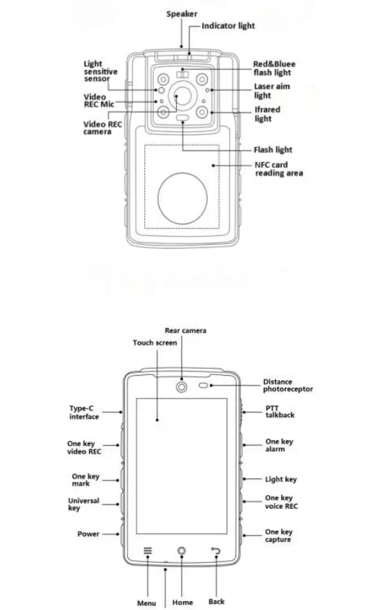
Structural sketch
Button and indicator light introduction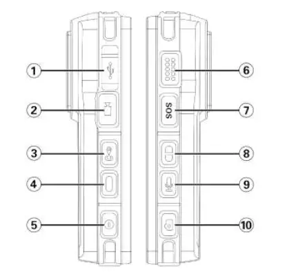
| No. | Item | Description |
| 1 | USB port | Use for files transmission, debugging, and charging |
| 2 | Video REC Key | Short press: video recording, press gain to stop the recording; Long press: upload/stop upload |
| 3 | Mark Key | Short press during recording: can be marked as important document with *mark |
| 4 | Universal | Short press to start laser, long press to start flash |
| 5 | Power | Short press: on/off screen; Long press: power on/off |
| 6 | Talkback | Press to speak for talkback or cluster |
| 7 | Alarm | Long press for 3 seconds to send alarm |
| 8 | Light Key | Short press open/shut red and blue flash; long press/shut night vision(only on manual mode) |
| 9 | Voice REC | Short press: start voice REC, press again to stop |
| 10 | Capture | Short press to capture |
Indicator light introduction
| No. | Name | Description |
| 1 | Flash light | Fill light or use as flashlight |
| 2 | IR lamp | Turn on IR lamp to fill light when light is not enough |
| 3 | Indicator light | Green light on: device turned on, or charging finished Red light twinkling: capture image Red light on: in video recording Yellow light on: in voice recording Blue light on: charging |
| 4 | Red/blue light | Flashing, use for caution, reminder |
Accessories interface
The terminal adopts type-c waterproof data interface, which can realize high-speed data transmission and quick charging.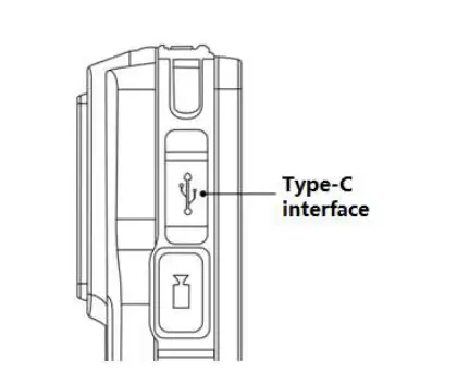
Pogo pin interface is adopted at the bottom of the terminal, which can be equipped with a special base charger to realize high-speed data transmission and quick charging.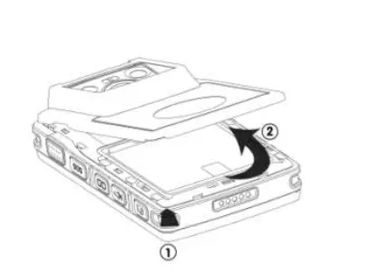
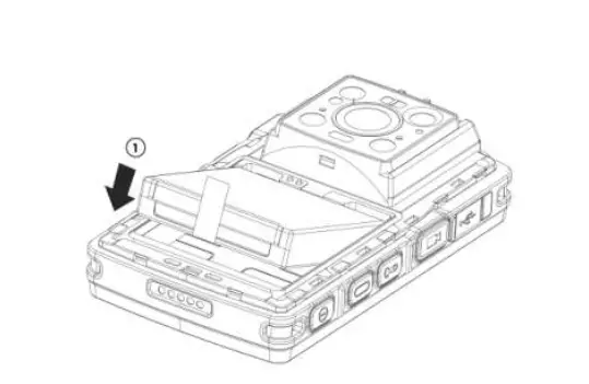
Insert and take out Naso-SIM card, TF card
Before installing or removing the Nano-Sim and TF cards, the terminal power should be turned off;
- Flip the terminal to the back side and open the battery cover from the button 1 of the batteAry cover according to the instructions in figure1-1.Lift the battery cover in the direction shown as 2;

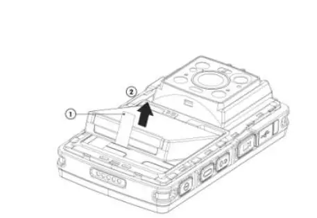
- According to sketch 1-2, pinch the battery handle 1, pull it in the direction indicated by the arrow, lift the battery and remove the battery;
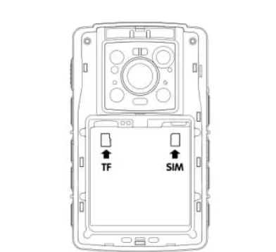
- Install Nano-SIM and TF card. According to sketch 1-3, push the metal contacts of the Nano-SIM card and TF card down into the slot completely (note the corner cut direction );

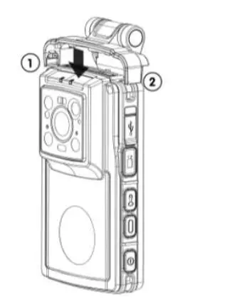
- As shown in sketch 1-4, point the battery metal contact at the metal point of the battery connector, press as per the direction of arrow 1, put it into the battery cabin until flat.

Back clamp installation and removel
- As shown sketch 1-5,when installing the device clamp, the clamp is stuck on the top of the device in the direction indicated by 1(pay attention to the installation direction, and check whether the two parts are stuck firmly after the installation.)

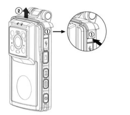
- As shown in sketch 1-6, first pull out the clasp at 1 place and then take off the clamp along the direction of 2.

Quick login guide
Quick login
- Long press the power button and wait for the device to start, enter the login interface.
- Click “setting” in the upper right corner, click platform setting, and set the device access platform parameters.
- After the setting, return to the login interface and fill in the user name and password to login; (please confirm the net work connection status of the device before login, set WiFi connection or 4G access parameters in advance) After the device logs in the emergency command platform, it can check the real-time video of the device by logging in the emergency command client ( the account of the same department). After opening the intercom, it can have two-way intercom with other body cameras.
Main interface
After logging in, enter the main interface, as shown in the figure below, the main interface displays all the functional modules of the device.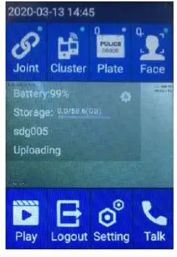
Function module description:
| No. | Name | Description |
| 1 | Login status | Shows connection status: Joint:Round point is green Broken:Round point is gray Joining:Yellow point twinkling |
| 2 | Cluster | Shows whether joint the group ( only support the emergency platform ):joint group: round point is always green. Un-joined group: grey; Click to get in cluster interface to create a cluster or to shout in a joined group. |
| 3 | Plate | Shows license plate capture quantity (shows default icon and quantity zero), click to open picture list |
| 4 | Face | Shows face image capture quantity (shows default icon and quantity zero), click to open picture list |
| 5 | Playback | Click to enter the file management interface, can view video recording, audio recording, pictures, the last time video recording and pictures |
| 6 | Logout | Click “logout”, and click OK back to login interface, can log in again with same account, or select other user account, or input a new user account |
| 7 | Setting | Click to enter the setting interface, to display the menu of platform setting, video setting, audio setting and other settings |
| 8 | Talk | Click to enter call interface to view recent calls and contacts, and request talkback (emergency platform only) |
Setting interface
Click “Setting” to enter the parameter setting interface, which displays the menu of platform setting, video setting, audio setting, intelligent identification setting, other settings, storage path setting, system setting, cache clearing, about, logout, etc.
Platform Setting
In the “setting” menu, click “platform settings” to enter the platform setting interface, you can modify the IP address or port.
Video setting
From the “setting” menu, click “video settings” to change the video resolution or snapshot resolution.
Audio setting
In the “settings” menu, click “audio setting, to select audio type, volume output level and sampling frequency option, then configure separately.
Intelligent Recog setting
In the “settings” menu, click “intelligent setting” to select the intelligent algorithm, Click “Arithmetic type” to select recognition mode ( face, plate or non). FR and LPR can’t be used at the same time. Whether ID card identification is enabled or not, does not affect other recognition modes.
Another setting
In the settings, you can set whether the GPS upload, collection mode, upload interval, then maximum storage time of the uploaded file, whether loop coverage, upload log and turning on the infrared light mode.
Recording interface
Press recording key, enter recorder page, start recording, click the key again to end the recording.
Logout interface
Click “Logout”, and click OK, it will be back to login interface, you can log in again with the same account, or select historical user to log in, or input new user to log in.
Files management interface
Click” File management” to enter the file management interface, you can view the captured pictures, sound recording, video recording, and upload them to the server.
Cluster interface
Click “Cluster” to enter the cluster interface, you can have group calling in the group joined.
Talk & Talkback interface
Enter the intercom interface to view recent calls, contacts and request intercom.
Technical parameters
| Item | Description | |
| System | OS | Android 8.1 |
| Display | screen | 3.5″ 320*480 flat capacitive multi-point touch screen |
|
Video | Camera | Front 16.0 mega CMOS, support IR, laser shooting and positioning of video recording; Rear 2.0 mega for video intercom |
| Coding | H.264 | |
| Resolution | 1080P、720P、640*480 optional | |
| Capture | Support JEPG format picture, resolution optional, max 16 mega pixel | |
| Audio | MIC | Built in MIC, use for intercom and video sound input |
| Speaker | Built in speaker, use for talkback and calling output | |
| Intercom | Support two-way voice talkback | |
| Storage | Built in | Standard configure 64G,32G or 128G optional |
| Video format | MP4 | |
| Network | 4G/3G | 4Gall net, support LTE-TDD, LTE-FDD, WCDMA, etc. |
| WiFi | Built in WiFi module and antenna, support 2.4G/5G | |
| Bluetooth | Built in Bluetooth module and antenna, support BT4.1 | |
| Power | Charging | Type-C interface,DC 5V/2000mA |
| Battery | Remove able [email protected] polymer Li-ion battery | |
| Positioning | BD&GPS | Support BD/GPS double mode positioning |
| AGPS | Support AGPS | |
| Protection | Level | IP68 |
| Drop | Na damage after 2m drop on each face | |
| Environment | Working Temperature | Normal working temperature:-10℃~50℃ Limit working temperature:-30℃~55℃ |
| Working humidity | <90% | |
|
Accessories | charger | 5V/2A charger 1pc |
| Data cable | Type-C cable 1pc | |
| Clip | Back clip 1pc | |
| User manual | User manual 1pc | |
| Battery | 2700mAh Li-ion battery 1pc | |
| Appearance | Dimensions | 109mm(L)×66mm(W)×17mm(H) |
| Weight | 192g |
Common troubleshooting list
Terminal maintenance should follow the principle from:
| Fault phenomenon | Fault Judgment | Trouble Removal |
| Terminal can’t start | Run out of battery | Fully charge for more than 2 hours |
| Terminal system stuck | System unresponsive | Long press power key for seconds restart |
| Terminal short work time | Under charge or battery fault | Fully charge more than 2 hrs, or replace |
| Copying data to computer interrupt in the middle | USB interface of front panel of the computer is under power | Suggest to connect data cable to the USB port on the back panel of the computer |
| Computer can’t identify terminal | Data cable problem | Change data cable |
| Driver not install successfully | Reinstall driver until success |
SAR Information Statement
The product is designed and manufactured not to exceed the emission limits for exposure to radiofrequency (RF) energy set by the Federal Communications Commission of the U.S. Government. These limits are part of comprehensive guidelines and establish permitted levels of RF energy for the general population. The guidelines are based on standards that were developed by independent scientific organizations through periodic and thorough evaluation of scientific studies. The standards include a substantial safety margin designed to assure the safety of all persons, regardless of age and health. The exposure standard for wireless mobile phones employs a unit of measurement known as the Specific Absorption Rate, or SAR. The SAR limit set by the FCC is 1.6 W/kg. Tests for SAR are conducted with the product transmitting at its highest certified power level in all tested frequency bands. Although the SAR is determined at the highest certified power level, the actual SAR level of the product while operating can be well below the maximum value. This is because the product is designed to operate at multiple power levels so as to use only the power required to reach the network.
In general, the closer you are to a wireless base station antenna, the lower the power output. Before a product model is available for sale to the public, it must be tested and certified to the FCC that it does not exceed the limit established by the government adopted requirement for safe exposure. The tests are performed in positions and locations (e.g., at the ear and worn on the body) as required by the FCC for each model. The highest SAR value for this model product when tested for use worn on the body, as described in this user guide, when properly worn on the body is 1.164W/kg. (Body-worn measurements differ among phone models, depending upon available accessories and FCC requirements). While there may be differences between the SAR levels of various product and at various positions, they all meet the government requirement for safe exposure. The FCC has granted an Equipment Authorization for this model product with all reported SAR levels evaluated as in compliance with the FCC RF exposure guidelines. SAR information on this model product is on file with the FCC and can be found under the Display Grant section of http://www.fcc.gov/ oet/fccid after searching on.
FCC ID: 2AWIA-DSJTSP26A1
Additional information on Specific Absorption Rates (SAR) can be found on the Cellular Telecommunications Industry Asso-ciation (CTIA) web-site at
https://www.ctia.org/ In the United States and Canada, the SAR limit is 1.6 watts/kg (W/kg) averaged over onegram of tissue. The standard incorporates a sub-stantial margin of safety to give additional protectionfor the public and to account for any variations in measurements.
Body-worn Operation
This device was tested for typical body-worn operations. To comply with RF exposure requirements, a minimum separation distance of 10mm is used between the user’s body and the handset, including the antenna. Third-party belt-clips, holsters, and similar accessories used by this device should not contain any metallic components. Body-worn accessories that do not meet these requirements may not comply with RF exposure requirements and should be avoided. Use only the supplied or an approved antenna.


