GREENHECK Sure-Aire Flow Measurement Stations User Manual

Installation, Operation and Maintenance Manual
Please read and save these instructions for future reference. Read carefully before attempting to assemble, install, operate or maintain the product described. Protect yourself and others by observing all safety information. Failure to comply with these instructions will result in voiding of the product warranty and may result in personal injury and/or property damage.
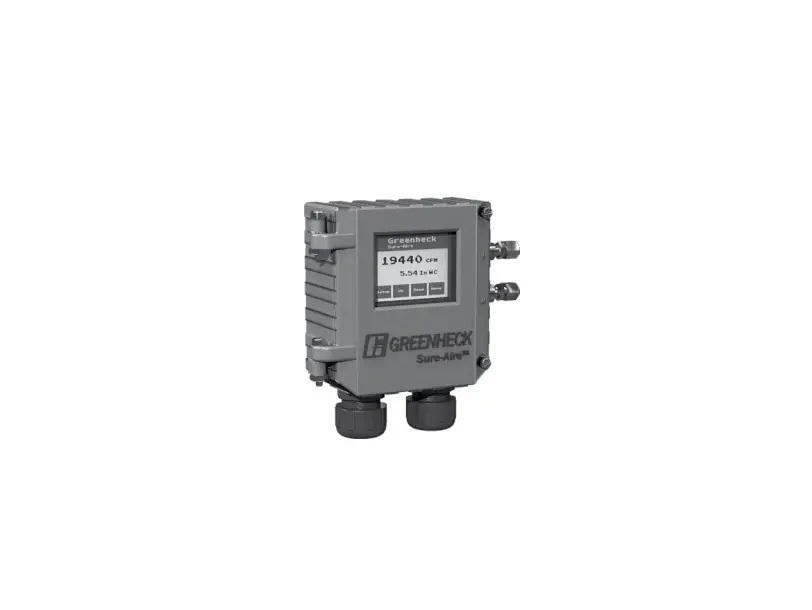
Sure-Aire™ Electronics Features:
- LCD display with user-friendly touch panel interface
- NEMA-4 / IP56 enclosure rating
- Factory calibrated
- Programmable elevation
- English or metric readings
- 24 VAC / DC or 100-240 VAC 50 / 60 Hz input voltage
- Part numbers and pressure ranges:
386719 – 0-4.15 in. wg
386720 – 0-8.30 in. wg
386721 – 0-22.14 in. wg
386722 – 0-41.52 in. wg
386723 – 0-83.14 in. wg
386724 – 0-138.40 in. wg
Pressure ranges reflect differential pressures between the fan inlet and inlet cone, not system static pressure.
- Isolated output, linear to differential pressure or
volume
4-20 mA
2-10 VDC - Communication protocols
BACnet MSTP
Modbus - Temperature compensation for air density
Tools Required
- Four (4) #8-32 screws
- 1/4-inch nylon tubing (length dependent on distance between fan and Sure-Aire electronics, maximum 75 feet (23 m) each line)
- Sensor wiring for temperature sensor (if temperature sensor is being used)
Flow Accuracy – +/- 3.0% of actual flow
Transducer in Electronics
- Accuracy +/- 0.5% of full scale at 77ºF (25ºC)
- Pressure limit: 70 psi (1938 in. wg)
- Thermal effects: 0.015%/°F (0.027%/°C) from -13° thru 185°F ( 25° thru 85°C)
WARNING
Improper installation, adjustment, alterations, service or maintenance may cause injury and / or property damage, as well as possibly void the factory warranty. No person may install, operate,
or maintain a Sure‑Aire™ electronics without first being fully trained and qualified in the installation, operation and maintenance, and carefully reading and understanding the contents of this manual. If you have
any questions about these instructions, contact your local representative.
CAUTION
Risk of electrical shock! More than one disconnect switch may be required to de-energize the equipment before servicing.
Label Information
General Information
This instruction manual provides installation, operating, maintenance, and other information for the Sure-Aire™ electronics.
Receiving
Upon receiving the electronics, check to ensure all items are accounted for by referencing the packing list. Inspect each crate or carton for shipping damage before accepting delivery. Alert the carrier of any damage detected. The customer will make notification of damage (or shortage of items) on the packing list and all copies of the bill of lading which is countersigned by the delivering carrier. If damaged, immediately contact your local sales representative.
Any physical damage to the unit after acceptance is not the responsibility of the manufacturer.
Unpacking
Verify that all required parts and the correct quantity of each item have been received. If any items are missing, report shortages to your local representative to arrange for obtaining missing parts.
Storage
Electronics are protected against damage during shipment. If the electronics cannot be installed and operated immediately, precautions need to be taken to prevent deterioration during storage. The user assumes responsibility of the electronics and any accessories while in storage. The manufacturer will not be responsible for damage during storage. These suggestions are provided solely as a convenience to the user.
The ideal environment for the storage of electronics is indoors, above grade, in a low humidity atmosphere which is sealed to prevent the entry of blowing dust, rain or snow. Temperatures should be evenly maintained between 30° to 110°F (-1° to 43°C). Wide temperature swings may cause condensation and “sweating” of metal parts. All accessories must be stored indoors in a clean, dry atmosphere.
Removing from Storage
As electronics are removed from storage to be installed in their final location, they should be protected and maintained in a similar fashion until the control goes into operation. Environmental Operation Range: -4° to 140°F (-20° to 60°C).
Installation
WARNING
When wiring the electronics, you must follow industry standard practices for controls and protect against electrostatic discharge (ESD). Failure to exercise good ESD practices may cause damage to the electronics
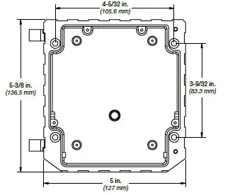
- Mount the electronics in the vertical plane using four (4) #8-32 screws, field supplied. Open the front cover by unscrewing the two captive thumb screws to gain access to the four mounting locations.
Note: Mount the Sure-Aire™ electronics within 75 feet of the fan.
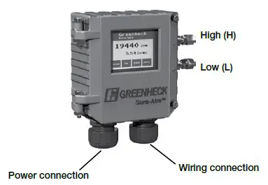
- Use 1/4-inch nylon tubing to connect the corresponding High (H) and Low (L), 1/4-inch quick connect, pressure ports of the Sure-Aire™ electronics to the high and low pressure ports on the fan.

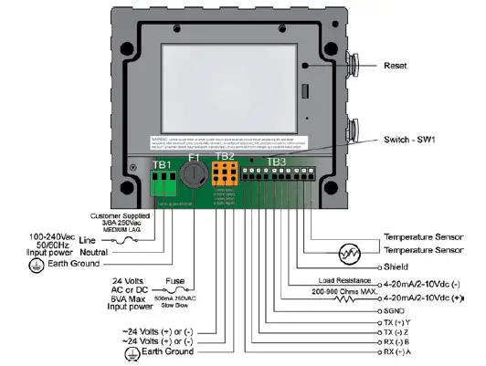
- Connect supply power:
Two input power options are available: 24 VAC / DC or 100-240 VAC. The wiring for each can be seen on page 4. Use 1/2‑inch liquid tight conduit to meet full IP rating.
Installation (continued)
4. Optional Wiring Connections
4.1 Analog Output Signal:
Both 4-20mA and 2-10VDC are available. Connect signal wire into corresponding terminals on block TB3. If using 4-20 mA, a load resistor between 200 and 900 ohms is required, field supplied. If two or more outputs share a common connection, a signal isolator may be required.
Update settings within electronics (see page 7): Use the touch screen to select the 4-20 mA or 2-10 VDC output signal via the setup menu.
4.2. Network Protocol:
Both BACnet MSTP and Modbus RTU are enabled. Connect appropriate wiring to block TB3. Adjust switch, SW1, to 2-wire (left) or 4-wire (right) as required. Reference network protocol section for more information. Update settings within electronics (page 7):
Switch SW1: 2-Wire / 4-Wire Select:
- Left Position = 2-Wire
- Right Position = 4-Wire
4.3. Temperature Density Compensation:
Temperature compensation can adjust airflow calculation based on changing airstream temperatures. If temperature compensation is not used, the air density value will be a function of standard air (70°F / 21°C). The supplied sensor measures the exterior temperature of the ductwork, only screw holes are required.
Mount the sensor in contact with the ductwork.
Wire the temperature sensor into corresponding terminals on block TB3 (wiring supplied by others).
Update settings within electronics (page 5): In the setup menu change Temperature Compensation to “Yes”. Confirm that this is set to “Yes”.
4.Close and tighten screws on cover:
When the required preceding steps are complete, make sure the front cover is properly aligned to the housing and the two captive thumb screws are securely tightened
Wiring Diagram
Display Setting Options and Setup
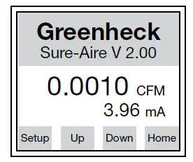
The electronics is equipped with a touchscreen LCD display. There are 4 navigation buttons on the bottom of the screen. Button names will change based on the
parameter you are in (i.e. “Setup” will change to “Home” and “Home” will change to “Edit”).
Home Screen
To view settings use the “Up” and “Down” buttons to scroll through the list. To adjust settings, press “Setup” and scroll through the settings. Below is information on the adjustable settings.
Home Screen: Top/Bottom View: Press “Edit“ to change Main Display Value. Press “Prev“ or “Next“ to adjust what reading displays on the Home screen, then press “Enter“ to store the value.
- Flow (default top display)
- Pressure
- Temperature
- Air density
- Output signal (default bottom display)
- Velocity
- None
Measurement System: Press “Edit“ to change the measurement system units. Press “Prev“ or “Next“ to adjust, then press “Enter“ to store the value.
- English (default)
- Metric
K-Factor: Press “Edit“ to change K-Factor. Press “Inc“ or “Dec“ to adjust, then press “Enter“ to store the value.
- 200 to 30,000
(Factory set to fan model and size)
Elevation: Press “Edit“ to change elevation. Press “Inc“ or “Dec“ to adjust, then press “Enter“ to store the value.
- 0 – 10,000 ft
- (0 ft default)
Outlet Area: Press “Edit“ to change the stack outlet area. Press “Inc“ or “Dec“ to increase or decrease the area, respectively. Then press “Enter“ to store the value.
- 0-10 Ft²
Display Brightness: Press “Edit“ to change brightness. Press “Inc“ or “Dec“ to adjust, then press “Enter“ to store the value.
- 10 – 100%
- (80% default)
Air Flow Units: Press “Edit” to change Air Flow Units. Press “Prev” or “Next” to adjust, then press Enter to store the value.
- CFM (default)
- m³/hr
- m³/min
Pressure Units: Press “Edit“ to change pressure units. Press “Prev“ or “Next“ to adjust, then press “Enter“ to store the value.
- wg (default)
- Ft wg
- mm wg
- cm wg
- PSI
- Hg
- mm Hg
- mBar
- Pa
- kPa – kilopascals (1kPa = 1000 Pa)
- hPa – hectopascals (1hPA = 100 Pa)
- In.
Temperature Compensation: Press “Edit“ to change Temperature Compensation. Press “Prev“ or “Next“ to adjust, then press “Enter“ to store the value.
- Yes (default)
- No
Note: If temperature compensation is set to “No“, the air density will be a function of standard temperature (70°F / 21°C).
Analog Output Signal: Press “Edit“ to change Output Signal type. Press “Prev“ or “Next“ to adjust, then press “Enter“ to store the value.
- 4-20 mA (default)
- 2-10 VDC
Linearize By: Press “Edit“ to change the linearization settings. The electronics will linearize the electronics output with respect to this setting.
- Flow (default)
- Pressure
Note: The maximum measurable flow rate will automatically calculate based on the electronics settings. The maximum flow rate is displayed on the screen.
WARNING
Due to load resistance change from product to product, it may be necessary to recalibrate the 4-20 mA electronics. See 4-20 mA transducer calibration procedure.
Display Setting Options and Setup (continued)
Network Protocol: See page 7. Select the appropriate protocol, baud rate and network address.
Defaults
Load Factory Defaults: Press “Edit“ to load factory defaults. Press “Prev“ or “Next“ to select “Yes“, then press “Enter“.
- No (default)
- Yes (changes all settings to factory default)
Load Customer Defaults: Press “Edit“ to load customer defaults. Press “Prev“ or “Next“ to select “Yes“, then press “Enter“.
- No (default)
- Yes (loads all customer default settings)
Save Customer Defaults: Press “Edit“ to save current electronics settings as the customer default. Press “Prev“ or “Next“ to select “Yes“, then press “Enter“.
- No (default)
- Yes (saves current settings as the customer default)
Network Protocol – Optional
Greenheck’s Sure-Aire™ electronics has the ability to connect to a Building Automation System (BAS) through the on-board RS-485 port. The electronics can be configured as either BACnet MS/TP or Modbus RTU Slave. When in the display menu, scroll through the options until the Network Protocol screen. Pressing edit will permit changing the network protocol type and associated data. This information should be set to match the BAS.
BACnet MS/TP Server
When the electronics is configured for BACnet, it will expose a total of eight (8) objects on the network.
| BACnet MS/TP Server Device Settings | |
| Setting | Value |
| Baud Rate | Set to match BMS |
| Parity | No Parity (1 Stop Bit) |
| APDU Timeout (ms) | 1000 |
| Number of APDU Retries | 3 |
| Max Master Address | 127 |
| Max Info Frames | 1 |
| BACnet MS/TP Server Objects | |||
| Object Name | Object Type | Data Type | Units |
| Sure-Aire™ | Device Object | N/A | N/A |
| K-Factor | Analog Input | 16-Bit Unsigned | None |
| Elevation | Analog Input | 16-Bit Unsigned | None |
| Outlet Area | Analog Input | 32-Bit Floating Point | None |
| Flow Temperature | Analog Input | 16-Bit Signed | None |
| Pressure | Analog Input | 32-Bit Floating Point | None |
| Volume | Analog Input | 32-Bit Floating Point | None |
| Velocity | Analog Input | 32-Bit Floating Point | None |
Modbus RTU Slave
When the electronics is configured for Modbus, it will expose a total of seven (7) registers on the network. The Modbus RTU Slave settings and list of registers can be seen below
| Modbus RTU Slave Device Settings | |
| Setting | Value |
| Baud Rate | Set to match BMS |
| Parity | No Parity (1 Stop Bit) |
| Timeout (ms) | 0 |
| Response Delay (ms) | 0 |
| Modbus RTU Slave Registers | |||
| Register Name | Register Type | Data Type | Units |
| K-Factor | Input Register | 16-Bit Unsigned | None |
| Elevation | Input Register | 16-Bit Unsigned | None |
| Outlet Area | Input Register | 16-Bit Unsigned | None |
| Flow Temperature | Input Register | 16-Bit Unsigned | None |
| Pressure | Input Register | 16-Bit Unsigned | None |
| Volume | Input Register | 16-Bit Unsigned | None |
| Velocity | Input Register | 16-Bit Unsigned | None |
NOTE
All of the objects / registers that are exposed on the network do not have a unit associated with them. The units of the values exposed on the network will be based on the units that are selected on the Sure-Aire™ electronics
Analog Output Signal – Optional
Greenheck’s Sure-Aire™ differential pressure electronics provides either a 2-10 VDC or 4-20 mA analog output signal. The output signal can be configured linearly proportional to either the pressure range or the flow within the setup. The ranges for Greenheck’s Sure-Aire™ electronics are listed by model on cover.
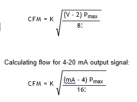
Voltage and Amperage Signal
If using the analog signal linear to flow, the max flow is automatically calculated based on the pressure range and K-factor input into the electronics. The max value is displayed in the setup menu If output signal is linear to pressure, the corresponding equations are used to calculate the flow.
| K | Constant dependent on fan model and size (see page 9) |
| Pmax | Maximum pressure of electronics (in. wg) |
| | Air density (lb/ft³ °F) [0.075 at 70°F and 0 ft elevation] |
| V | Output voltage of 2-10 VDC signal |
| mA | Output current of 4-20 mA signal |
Calculation Using Manual Pressure Gauge or Third Party Transducer
Flow Rate Equation
The volumetric flow through the fan (cfm) can be calculated from the equation:
CFM = K
where K is the K-Factor for the specific fan model and size, ΔP is the measured differential pressure across the inlet cone (in. wg), and is the density of air (lb/ft³ °F).
Transducer Recalibration Procedure
The electronics are calibrated per order at the factory. Under certain circumstances, there may be a discrepancy of calibration once installed on site. The following procedure is used to re-calibrate the pressure trandsucer within the electronics. In the event an error occurs trying to re-calibrate, the transducer parameters can be re-set to factory settings using “Load Factory Settings” within the setup menu.
Equipment
Digital multimeter.
NOTE
Vacuum pressure device with gauge (only needed if calibrating upper range). 200-900 ohm resistor (only needed if calibrating using 4-20 mA).
Procedure
- Remove power to the electronics.
- Remove any wires connected on the analog outputs.
- Remove tubing from Sure-Aire™ electronics box, box uses push-to connect fittings. Push in on plastic ring and pull on tubing to remove.
- Connect multimeter to analog points on terminal strip. If calibrating using 4-20 mA, a series load resistorbetween 200 and 900 ohms is required.
- Set multimeter to the correct measurement units, VDC or mA.
- Apply power to the Sure-Aire™ electronics.
- Press the “Setup“ button on the LCD panel.
- Verify the analog signal is setup for your measurement and that the signal is linear to Differential Pressure.
- Go to the “Trans Min/Trans Max” screen. Record the values for each. It is correct that the trans min value is higher than the trans max value.
- Press “Enter / Edit”.
- With all tubing removed, adjust the trans min value up / down until the multimeter reads either 2 VDC or 4 mA.
- Press “Next”. If only calibrating low value, press “Enter” to complete.
- To calibrate upper range, apply the pressure device to the high port and pull vacuum to maximum pressure on Sure-Aire™ label.
- Adjust the trans max value up/down until the multimeter reads either 10 VDC or 20 mA.
- Press “Enter” to store the new value.
- Press “Exit” to return to the main screen.
- Go to “Save Customer Defaults” and save for future resetting to the changes.
K-Factors
| Size | APD | Size | APH / APM HPA | AFDW / BIDW | FJI | QEI / QEID | USF-500 & Vektor-C series | Vektor-H Belt Drive | Vektor-M series | |||||||||||||||
| 315 | 257 | 7 | not applicable | not applicable | 179 | not applicable | 179 | not applicable | not applicable | |||||||||||||||
| 355 | 329 | 8 | not applicable | not applicable | 179 | not applicable | 179 | not applicable | not applicable | |||||||||||||||
| 400 | 406 | 9 | not applicable | not applicable | 179 | 408 | 179 | 248 | not applicable | |||||||||||||||
| 450 | 536 | 10 | not applicable | not applicable | 179 | not applicable | 179 | 202 | not applicable | |||||||||||||||
| 500 | 652 | 12 | 355 | 592 | 244 | 408 | 244 | 296 | not applicable | |||||||||||||||
| 560 | 847 | 13 | not applicable | 701 | not applicable | not applicable | 296 | 351 | not applicable | |||||||||||||||
| 630 | 1053 | 15 | 355 | 861 | 366 | 603 | 366 | not applicable | 526 | |||||||||||||||
| 16 | 421 | 1062 | not applicable | 724 | 443 | 531 | 634 | |||||||||||||||||
| 18 | 517 | 1083 | 542 | 897 | 542 | 787 | ||||||||||||||||||
| 20 | 617 | 1301 | 651 | 1088 | 651 | not applicable | 955 | |||||||||||||||||
| 22 | 759 | 1610 | 805 | 1321 | 805 | 1161 | ||||||||||||||||||
| 24 | 913 | 1964 | 976 | 1631 | 976 | 1436 | ||||||||||||||||||
| 27 | 1105 | 2369 | not applicable | 1962 | 1186 | not applicable | 1729 | |||||||||||||||||
| 30 | 1355 | 2928 | not applicable | 2400 | 1464 | 2116 | ||||||||||||||||||
| 33 | 1625 | 3540 | not applicable | 2923 | 1771 | not applicable | 2581 | |||||||||||||||||
| 36 | 1967 | 4336 | not applicable | 3576 | 2167 | 3154 | ||||||||||||||||||
| 40 | 2361 | 5259 | not applicable | 4331 | 2635 | not applicable | 3825 | |||||||||||||||||
| 44 | 2854 | 6440 | not applicable | 5318 | 3220 | not applicable | 4698 | |||||||||||||||||
| 49 | 3411 | 7808 | not applicable | 6525 | 3905 | not applicable | 5766 | |||||||||||||||||
| 54 | 4121 | 9571 | not applicable | 7891 | 4786 | not applicable | 6975 | |||||||||||||||||
| 60 | 4972 | 11707 | not applicable | 9648 | 5855 | not applicable | not applicable | |||||||||||||||||
| 66 | 5960 | 14166 | not applicable | not applicable | 7084 | not applicable | not applicable | |||||||||||||||||
| 73 | 7276 | 17330 | not applicable | not applicable | 8667 | not applicable | not applicable | |||||||||||||||||
| Vektor-H Direct Drive | ||||||||||||||||||||||||
| Fan Size | Nozzle Size | |||||||||||||||||||||||
| 4 | 5 | 6 | 7 | 8 | 9 | 10 | 11 | 12 | 13 | 14 | 15 | 16 | 17 | 18 | 19 | |||||||||
| 10 | 487 | 511 | 540 | 547 | 554 | 563 | 573 | – | – | – | – | – | – | – | – | – | ||||||||
| 12 | 577 | 616 | 664 | 674 | 685 | 697 | 700 | 704 | 708 | – | – | – | – | – | – | – | ||||||||
| 13 | – | – | – | 839 | 851 | 861 | 868 | 872 | 876 | 880 | – | – | – | – | – | – | ||||||||
| 14 | – | – | – | – | 1223 | 1239 | 1257 | 1260 | 1263 | 1267 | 1272 | – | – | – | – | – | ||||||||
| 16 | – | – | – | – | 1290 | 1409 | 1542 | 1563 | 1586 | 1587 | 1588 | 1597 | 1607 | – | – | – | ||||||||
| 18 | – | – | – | – | – | 1923 | 1937 | 1952 | 1965 | 1979 | 1990 | 2003 | 1994 | 1983 | 1995 | 2007 | ||||||||
| 20 | – | – | – | – | – | 2248 | 2296 | 2348 | 2367 | 2387 | 2408 | 2431 | 2432 | 2432 | 2429 | 2426 | ||||||||
Our Commitment
As a result of our commitment to continuous improvement, Greenheck reserves the right to change specifications without notice.
Product warranties can be found online at Greenheck.com, either on the specific product page or in the literature
section of the website at Greenheck.com/Resources/Library/Literature.
Greenheck’s Sure-Aire™ Flow Monitoring System catalog provides additional information describing the equipment, fan performance, available accessories, and specification data.
AMCA Publication 410-96, Safety Practices for Users and Installers of Industrial and Commercial Fans, provides additional safety information. This publication can be obtained from AMCA International, Inc. at www.amca.org.


