![]() SERVICE MANUAL
SERVICE MANUAL
COBRA 20
SOLID STATE CITIZENS BAND 2-WAY RADIO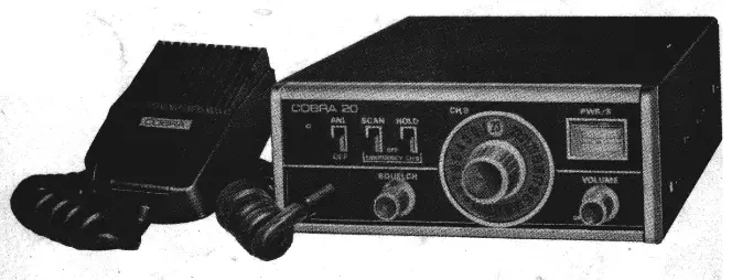 A PRODUCT OF DYNASCAN CORPORATION
1801 W. BELLE PLAINE AVE.. CHICAGO. ILLINOIS 60613
GENERAL DESCRIPTION
This Service Manual is used for COBRA 20 which are fully solid state 23 channel frequency synthesized 5W transceiver for class D Citizens Radio Service of FCC Rules and Regulations.
SPECIFICATIONS
| 2-1. | Receiver | |
| Sensitivity | 0. 5).1 V 10dB S+N/N @ 30% modulation @ 1000Hz | |
| Selectivity | 4 KHz @ -6dB 20 KHz @ -50dB | |
| Image rejection | better than 40dB | |
| Squelch | minimum sensitivity … V maximum signal stop, factory setting, 100kiV | |
| Noise limiter | series gate type | |
| Audio output | 2. 5 watts 8-ohm speaker high-level class B audio | |
| 2-2. | Transmitter | |
| Power output | better than 3. 0 watts @ 13. 8 volts | |
| Modulation | better than 90% | |
| 2-3. | Microphone | dynamic microphone 500 |
| 2-4. | Weight | 4. 5 pound |
| 2-5. | Size | 2. 36″ (H) x 6. 0″ (W) x 8. 46 ” (D) |
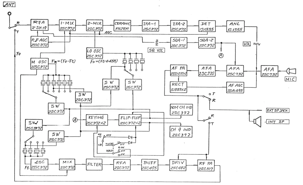
BLOCK DIAGRAM OF TRANSCEIVER COBRA 20
 ALIGNMENT INSTRUCTIONS
Note: This transceiver meets all requirements of FCC Rules and Regulations Parts 95, Subpart ‘C”, and requires a station license. Therefore only those persons properly licensed
by the FCC are permitted to repair or adjust any malfunctioning unit found to be transmitting or radiating illegally.
4-1. Receiver
a. Connects an oscilloscope or VI’VM to test point D
b. Inject 455 kHz 30% modulated signal at test point © using a 0.01 mfd capacitor in series with the signal generator cable. : ce. Adjust 2nd IF transformers T4 and T5 for maximum deflection.
d. Connect a signal generator to Jl. Inject 27 MHz 30% modulated signal of about 10001V.
e. Adjust ist IF transformers 13 decreasing the signal generator output.
f. Adjust RF transformers T1 and [2 decreasing the signal generator output.
g. Check the receiver specifications.:
4-2. Transmitter
a. Connect 50 ohms dummy load to J1.
b. Connect an oscilloscope to test point G :
c. Depress the press talk switch on the microphone and make sure 2 + 0.2 peak-to-peak synthesizer output.
d. Disconnect the oscilloscope from test point G.
e. Connect the oscilloscope to Jl and adjust T10, Tl1, and L3 for maximum deflection.
f. Adjust C60 for 3. 5W RF output.
TROUBLESHOOTING
5-1. Test equipment
a. RF signal generator, with a frequency range of at least from 455 kHz to 30 MHz, from 1 microvolt to 100 millivolts.
b. Oscilloscope, with a range of 30 MHz.
c. DC power source, 10~ 15 volts 3 amperes.
d. _ RF power meter with 50 ohms dummy load, with a full scale of at least 5.0 watts.
e. Multimeter.
f. VIVM with a full scale of at least 50 volts.
g- 8-ohm dummy lead with plug.
5-2. ° Precautions in troubleshooting
a. Tests are made on DC 13. 8V.
b, Antenna connector must be connected to signal generator or 50-ohm dummy load.
ce. EXT connector is connected to an 8-ohm dummy load to measure audio output.
5-3. Receiver (RF – IF stage)
| STEP | TROUBLE | CAUSE |
| 1 | Zero or excessive low voltage at RF-IF stage circuit power source line. | defective R25, broken Q6 or short-circuited T4, T5. |
| 2 | No signal output (455 kHz) | defective Q4, Q5, Q,6, short-circuited T4, T5. |
| 3 | No signal output (10 MHz band) | no oscillation of Q14, defective Q3, short-circuited T3. |
| 4 | No signal output (27 MHz band) | no oscillation of Q11, defective Q2, short-circuited Ti, T2. |
5-4. Receiver (audio circuit)
| STEP | TROUBLE | CAUSE |
| 1 | No signal output | defective Q33, Q34, Q35, Q36 |
| 2 | Excessive distorted signal | defective CD19 |
5-5.Transmitter
| STEP | TROUBLE | CAUSE |
| 1 | Zero or excessive low voltage at RFPA stage. | bad contact of Klb, dis-connection of T14. |
| 2 | No RF output (Final 5 stages) | defective Q23, Q24, Q25, Q,26, Q,27. |
| 3 | No RF output | no oscillation of Q,11, Q,22. |
| 4 | Normal RF output but no modulation | layer short-circuited T14, miss connection of MK1. |
5-6 Others
| STEP | TROUBLE | CAUSE |
| a. RF compressor | ||
| 1 | No or excessive small signal at over 1-volt signal. | defective Q1, CD12, CD13, no AGC behavior. |
| b. AF compressor (Transmitter) | ||
| 1 | Excessive modulation or excessive distortion. modulation waveform. | defective Q32, CD20, CD21, R110, R111 |
| c. Squelch control | ||
| 1 | Squelch control does not disconnect CD18, (does not quiet R83. the receiver even in ON position) | disconnected CD18,defective R83. |
| 2 | Squelch control does not function (quiets even in R83. OFF position) | shortened CD18 defective R83 |
| STEP | TROUBLE | CAUSE |
| d.S meter | ||
| 1 | Meter does not swing | defective CD3, Ml, R17. |
| e. RF meter | ||
| 1 | Meter does not ‘swing | defective CD11, Ml, R78. |
| f. ANL | ||
| 1 | ANL does not function (not effective) | disconnection S4, defective CD5. |
| 2 | ANL does not function (signal drop is excessive) | short circuit CD13. |
| g. CH9 scan aleat | ||
| 1 | CH9 scan circuit does not function when scan switch is ON position. | disconnected 82, 83, the open circuit of CD6, Q17, no oscillation of Q,15, Q16, the open circuit of CD7, CD8, defective Q18, Q19. |
| 2 | CH9 scan circuit does not stop by an incoming signal when scan switch is ON position. | short circuit of Q17, defective Q28, Q29, and CD6. |
| 3 | CH9 hold circuit does not function when scan and hold switches are ON position. | disconnected. 32, 33, defective R52. |
FREQUENCY SYNTHESIS
| Channel | ( Fo ) Frequency ( Paz ) | M0.30 ( Fm ) | ROS0( Fr ) | TOW ( Ft ) | |||||||||||
| X1 | X2 | X3 | A4 | X5 | X6 | X7 | X8 | X9 | X10 | X11 | X12 | X1A X1 | |||
| 59V9T | 17. | S70*LI | SIVIA | siva | 5/5•6 | S5S*6 | 695’6 | sps.6 | 000’01 | OIC’OI | 0e0’01 | 070s0T | |||
| 1 | 27. | 0 | 0 | 0 | |||||||||||
| 2 | 27. | 0 | O | 0 | |||||||||||
| 3 | 27. | 0 | 0 | 0 | |||||||||||
| 4 | 27.005 | O | 0 | 0 | |||||||||||
| 5 | 27. | 0 | 0 | 0 | |||||||||||
| 6 | 27. | 0 | 0 | 0 | |||||||||||
| 7 | 27. | 0 | 0 | 0 | |||||||||||
| 8 | 27. | 0 | 0 | ||||||||||||
| 9 | 27. | 0 | 0 | 0 | |||||||||||
| 10 | 27. | 0 | O | 0 | |||||||||||
| 11 | 27. | 0 | 0 | 0 | |||||||||||
| 12 | 27. | 0 | 0 | 0 | |||||||||||
| 13 | 27. | O | 0 | 0 | |||||||||||
| 14 | 27. | 0 | 0 | 0 | |||||||||||
| 15 | 27. | 0 | 0 | 0 | |||||||||||
| 16 | 27. | 0 | 0 | ||||||||||||
| 17 | 27. | 0 | 0 | 0 | |||||||||||
| 18 | 27. | 0 | 0 | 0 | |||||||||||
| 19 | 27. | O | 0 | ||||||||||||
| 20 | 27. | 0 | 0 | 0 | |||||||||||
| 21 | 27. | o | 0 | 0 | |||||||||||
| 22 | 27. | O | 0 | ||||||||||||
| 29 | 27. | 0 | 0 | 0 | |||||||||||
Formulae at frequency synthesis
Fo s Fm + Ft
455 kHz = Fo Fm – Fr Ft – Fr ( circle mark in the table )
( circle mark in the table )
COBRA 20 VOLTAGE CHART
SWITCH
| E | B | C | |
| Q30 | 0.0 | 13.0 | 0.0 |
AUDIO
| E | B | C | |
| Q31 | 0.6 | 1.2 | 0.6 |
| Q32 | 0.0 | C.0 | 0.0 |
| Q33 | 0.0 | 0.6 | 0.0 |
| Q314 | 0.0 | 0.0 | 14. |
| Q35 | 0.0 | 0.52 | 13.7, |
| Q36 | 0.0 | 0.52 | 14.7 |
* Using Demodulator Probe and 11 MzG VIVM
RECEIVE
| E | B | C | |
| Q1 | 1.96 | 1.55 | 1.15 |
| ,Q2 | 1.96 | 4.2 | 8.5 |
| Q3 | 1.55 | 2.2 | 9.6 |
| *Q14 | 2.2 | 2.65 | 9.6 |
| .Q5 | 0.0 | 0.63 | 9.7 |
| *Q6 | 1.4 | 2. | 9.9 |
| :Q7 | 0.0 | 0.65 | 0.0 |
| ,Q8 | 0.0 | 2.1 | 0.0 |
| ,c19 | 0.0 | 0.1 | 0.0 |
| ,Q10 | 0.0 | 0.0 | 0.0 |
| Q11 | 3.8 | 4.3 | 12.7 |
| Q12 | 0.0 | 0.0 | 0.2 |
| :Q13 | 0.0 | 0.6 | 0.0 |
| Q111 | 5.5 | 4.4 | 12.6 |
SCANNER
(NO SCAN)
(HOLD) SCAN ON
| E | B | C | E | B | C | |
| Q15 | 0.0 | 0.0 | 0.0 | 0.0 | 0.0 | 0.0 |
| 1Q16 | 0.0 | 0.0 | 0.0 | 0.0 | 0.0 | 0.0 |
| 1Q17 | 0.0 | 0.0 | 0.0 | 0.0 | 0.7 | 0.0 |
| .Q18 | 0.0 | 0.0 | 10. | 0.0 | 0.8 | 0.08, |
| .Q19 | 0.0 | 8. | 0.0 | 0.0 | 0.06 | 10. |
| , Q20 | 0.0 | 0.0 | 7. | 0.0 | 0.8 | 0.0 |
| Q21 | 0.0 | 0.8 | 0.0 | 0.0 | 0.0 | 7.4 |
TRANSMIT (MIKE KEYED)
| DC_VOLTS | RF_VOLTS* _ |
| E | B | C | E | B | C | |
| Q22 | 3.8 | 4.2 | 12.7 | 2.65 | 2.9 | 0.6 |
| Q23 | 3.0 | 3.6 | 12.1 | 0.65 | 1.4 | 0.7 |
| Q24 | 3.2 | 3.8 | 13.0 | o.65 | 9.0 | 0.7 |
| %25 | 0.0 | 0.0 | 13.7 | 0.4 | 3.0 | 13.0 |
| Q26 | 0.0 | 0.0 | 13.6 | 16.0 | 14.0 | 1.0 |
| ‘Q27 | 0.0 | 0.0 | 13.7 | 12.5 | 12.0 | 1.5 |
| UNSQUELCHED | SQUELCHED |
| E | B | C | E | B | C | |
| Q28 | 0.0 | 0.7 | 0.74 | 0.0 | 0.7 | 0.1 |
| °Q29 | 0.0 | 0.74 | 0.0 | 0.0 | 0.1 | 8.8 |


