
![]() MP-A20V Low-Z Amplifier
MP-A20V Low-Z Amplifier
User Manual TD-001572-01-B
EXPLANATION OF SYMBOLS
The term “WARNING!” indicates instructions regarding personal safety. If the instructions are not followed the result may be bodily injury or death.
The term “CAUTION!” indicates instructions regarding possible damage to physical equipment. If these instructions are not followed, it may
result in damage to the equipment that may not be covered under the warranty.
The term “IMPORTANT!” indicates instructions or information that are vital to the successful completion of the procedure.
The term “NOTE” is used to indicate additional useful information.
![]() NOTE:
NOTE:
The intent of the lightning flash with arrowhead symbol in a triangle is to alert the user to the presence of un-insulated
“dangerous” voltage within the product’s enclosure that may be of sufficient magnitude to constitute a risk of electric shock to humans.![]() NOTE:
NOTE:
The intent of the exclamation point within an equilateral triangle is to alert the user to the presence of important safety, and
operating and maintenance instructions in this manual.
![]() IMPORTANT SAFETY INSTRUCTIONS
IMPORTANT SAFETY INSTRUCTIONS![]()
![]() WARNING!:
WARNING!:
TO PREVENT FIRE OR ELECTRIC SHOCK, DO NOT EXPOSE THIS EQUIPMENT TO RAIN OR MOISTURE.
Elevated Operating Ambient – If installed in a closed or multi-unit rack assembly, the ambient operating temperature of the rack environment may be greater than room ambient. Consideration should be given to ensure that the maximum operating temperature range -10°C to 50°C (14°F to 122°F ) is not exceeded. Reduced Air Flow – Installation of the equipment in a rack should be such that the amount of airflow required for the safe operation of the equipment is not compromised.
- Read these instructions.
- Keep these instructions.
- Heed all warnings.
- Follow all instructions.
- Do not use this apparatus near water.
- Do not submerge the apparatus in water or liquids.
- Do not use any aerosol spray, cleaner, disinfectant, or fumigant on, near, or into the apparatus.
- Clean only with a dry cloth.
- Do not block any ventilation opening. Install in accordance with the manufacturer’s instructions.
- Keep all ventilation openings free of dust or other matter.
- Do not install near any heat sources such as radiators, heat registers, stoves, or other apparatus (including amplifiers) that produce heat.
- To reduce the risk of electrical shock, the power cord shall be connected to a main socket outlet with a protective earthing connection.
- Do not defeat the safety purpose of the polarized or grounding-type plug. A polarized plug has two blades with one wider than the other. A grounding-type plug has two blades and a third grounding prong. The wide blade or the third prong are provided for your safety. If the provided plug does not fit into your outlet, consult an electrician for the replacement of the obsolete outlet.
- Protect the power cord from being walked on or pinched particularly at plugs, convenience receptacles, and the point where they exit from the apparatus.
- Do not unplug the unit by pulling on the cord, use the plug.
- Only use attachments/accessories specified by the manufacturer.
- Unplug this apparatus during lightning storms or when unused for long periods of time.
- Refer all servicing to qualified service personnel. Servicing is required when the apparatus has been damaged in any way, such as power-supply cord or plug is damaged, liquid has been spilled or objects have fallen into the apparatus, the apparatus has been exposed to rain or moisture, does not operate normally, or has been dropped.
- The appliance coupler, or the AC Mains plug, is the AC mains disconnect device and shall remain readily accessible after installation.
- Adhere to all applicable, local codes.
- Consult a licensed, professional engineer when any doubt or questions arise regarding a physical equipment installation.
Maintenance and Repair
![]() WARNING!:
WARNING!:
Advanced technology, e.g., the use of modern materials and powerful electronics, requires specially adapted maintenance and repair methods. To avoid the danger of subsequent damage to the apparatus, injuries to persons, and/or the creation of additional safety hazards, all maintenance or repair work on the apparatus should be performed only by a QSC authorized service station or an authorized QSC International Distributor. QSC is not responsible for any injury, harm, or related damages arising from any failure of the customer, owner, or user of the apparatus to facilitate those repairs.
FCC Statement
![]() NOTE: This equipment has been tested and found to comply with the limits for a Class B digital device, pursuant to Part 15 of the FCC Rules.
NOTE: This equipment has been tested and found to comply with the limits for a Class B digital device, pursuant to Part 15 of the FCC Rules.
These limits are designed to provide reasonable protection against harmful interference in a residential installation. This equipment generates, uses and can radiate radio frequency energy and, if not installed and used in accordance with the instructions, may cause harmful interference to radio communications. However, there is no guarantee that interference will not occur in a particular installation. If this equipment does cause harmful interference to radio or television reception, which can be determined by turning the equipment off and on, the user is encouraged to try to correct the interference by one or more of the following measures:
- Reorient or relocate the receiving antenna.
- Increase the separation between the equipment and receiver.
- Connect the equipment into an outlet on a circuit different from that to which the receiver is connected.
- Consult the dealer or an experienced radio/TV technician for help.
RoHS STATEMENT
The QSC MP-A20V, MP-A40V, and MP-A80V amplifiers are in compliance with European Directive 2011/65/EU – Restriction of Hazardous Substances (RoHS2).
The QSC MP-A20V, MP-A40V, and MP-A80V amplifiers are in compliance with “China RoHS” directives. The following chart is provided for product use in China and its territories:
| QSC MP-A20V, MP-A40V, and MP-A80V Amplifiers | ||||||
| (Toxic or hazardous Substances and Elements) | ||||||
| (Part Name) | (Pb) | (Hg) | (Cd) | (Cr(vi)) | (PBB) | (PBDE) |
| (PCB Assemblies) | X | O | O | O | O | O |
| (Chassis Assemblies) | X | O | O | O | O | O |
| (O: Indicates that this toxic or hazardous substance contained in all of the homogeneous materials for this part is below the limit requirement in SJ/T11363_2006.) (X: Indicates that this toxic or hazardous substance contained in at least one of the homogeneous materials used for this part is above the limit requirement in SJ/T11363_2006.) | ||||||
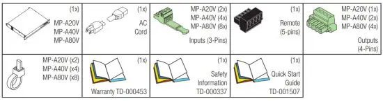
What’s in the Box
Installation
Rack-Mounting
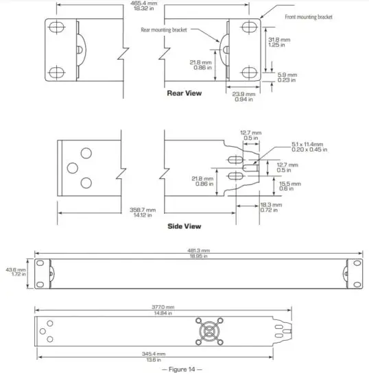
The MP-A amplifiers measure (HWD) 1.75 in x 19 in x 14.8 in (44 mm x 483 mm x 377 mm) and can be mounted into 1RU of a rack using four screws in the front, and four screws in the rear with the appropriate rear mounting support.
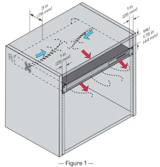
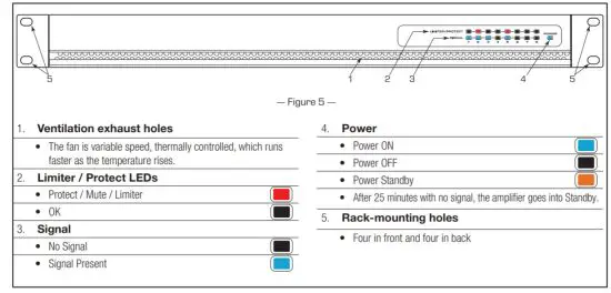
Ventilation
- The unit is cooled by a variable speed, thermally controlled fan which runs faster as the temperature rises.
 NOTE:
NOTE:
The MP-A Series of amplifiers are designed to maintain proper operating temperatures utilizing convection cooling via the aluminum chassis for typical background music loads. The variable-speed cooling fan(s) are thermally regulated and operate only during sustained high power output levels and/or high ambient temperature environments. - It is recommended that you provide 1RU (1.75 in / 44.45 mm) space above the amplifier.
- Minimum open space of 3 inches measured from the back of the amplifier.
![]() NOTE: QSC System Power Amplifiers contain advanced protection circuitry which allows them to reduce output power in order to maintain safe operating temperatures. Insufficient ventilation may result in the amplifier reducing output power during normal operation (indicated by Limiter/Protect LEDs illuminating red). To reduce the possibility of thermal limiting, and allow proper heat dissipation, we recommend that you keep the space directly above and to the rear of these amplifiers free of obstacles.
NOTE: QSC System Power Amplifiers contain advanced protection circuitry which allows them to reduce output power in order to maintain safe operating temperatures. Insufficient ventilation may result in the amplifier reducing output power during normal operation (indicated by Limiter/Protect LEDs illuminating red). To reduce the possibility of thermal limiting, and allow proper heat dissipation, we recommend that you keep the space directly above and to the rear of these amplifiers free of obstacles.
Introduction
Thank you for choosing a QSC MP-A Series amplifier. This manual provides a comprehensive guide to the features and functions of the MP-A20V, MP-A40V,
and MP-A80V amplifiers. Please read through this manual in its entirety to become fully acquainted with its functions and configuration options.
The MP-A Series power amplifiers are designed for Background Music and Paging applications. With class-D output circuitry, a switch-mode power
supply with active PFC, and Auto-standby power saving, the MP-A Series offer high efficiency and low cost of ownership. These amplifiers provide a
unique FlexAmp™ circuit topology that enables each pair of channels to deliver up to 400 Watts of total power in any ratio. This FlexAmp technology
when combined with the ability to drive any type of output load (4 Ω, 8 Ω, 70 V, 100 V) ensures extreme flexibility. Other useful features of the MP-A
Series include an 80Hz high-pass filter per channel, a remote standby contact, and amplifier status output for 3rd party system monitoring.
This manual was created for the MP-A20V, MP-A40V, and MP-A80V models. Any reference to “MP-A Series” in this manual refers to all models in the range.
FlexAmp™ Technology
FlexAmp technology simplifies system design by allowing a single amplifier with multiple channels to meet the needs of systems that would typically require several amplifiers of different power levels. FlexAmp technology achieves this by allowing the installer to configure each pair of channels (e.g. ch 1-2, or 3-4, etc.) to deliver up to 400 W combined output power, in any mix. This makes for an amazing amount of flexibility, especially when paired with the output mode switch that offers settings for 4 Ω, 8 Ω, 70 V, and 100 V.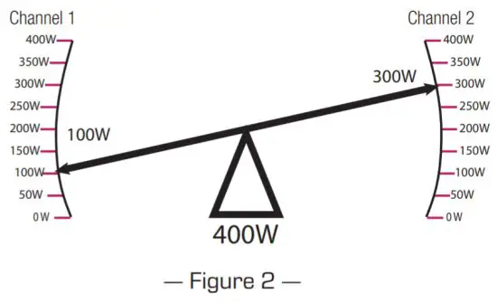
The MP-A series includes an 80 Hz high-pass filter for each output, as well as a remote input for putting the amplifier into standby mode for fire safety systems, and an amplifier status signal on the remote output for system verification.
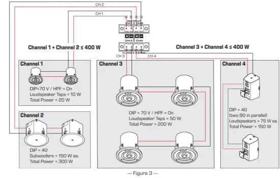
Figure 3 is an example of the versatility of the MP-A Series, Imagine the MP-A40V in a typical restaurant scenario:
- Channel 1 is set up in 70 V mode with the high-pass filter engaged, driving a pair of Hi-Z ceiling loudspeakers, transformer taps set at 10 W, in the restrooms
- Channel 2 is set up in 4 Ω mode driving a pair of Lo-Z, 150 W subwoofers for the main dining room.
- Channel 3 is set up with the high-pass filter engaged, 70 V mode, and four Hi-Z ceiling loudspeakers, transformer taps set to 50 W in the main dining room.
- Channel 4 is in 4 Ω mode driving two Lo-Z (8 Ω), 75 W surface-mount loudspeakers on the patio.
How to Set Up Your Loudspeakers and Amplifier
When designing your system, the best practice is to leave approximately 20% power headroom, leaving approximately 320 W for use.
Rules for the 4 Ω![]() and 8 Ω
and 8 Ω ![]() DIP Switch Settings (Refer to Figure 4)
DIP Switch Settings (Refer to Figure 4)
Use the 4 Ω setting for 4 Ω to 7 Ω loudspeakers; use the 8 Ω setting for 8 Ω or more.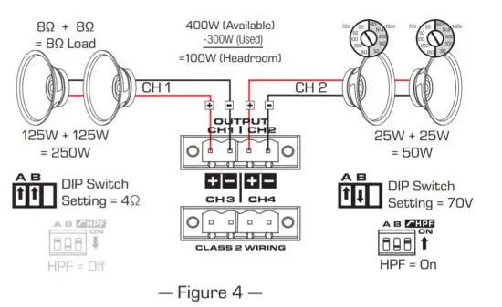
- Make sure the total, nominal impedance on the first channel equals either 4 Ω or 8 Ω and set the channel DIP switch to the appropriate 4 Ω or 8 Ω setting. In the example, two 8 Ω loudspeakers in parallel giving a 4 Ω load.
- Add the rated power of the connected loudspeakers on the first channel (125 W + 125 W = 250 W). This total is the maximum you will use on this channel. DIP Switch Setting = 4Ω
- Subtract the total rated power from 400 W and the remaining amount is what is available for the second channel. (400 W – 250 W = 150 W)
Rules for 100 V![]() and 70 V
and 70 V![]() DIP Switch Settings (Refer to Figure 4)
DIP Switch Settings (Refer to Figure 4)
- Connect your loudspeaker cable, in a daisy-chain fashion, from the channel output to the 70 V or 100 V loudspeakers.
- Set the transformer taps on the loudspeakers for the desired 70 V or 100 V power setting. Figure 4 shows the DIP switch set to 70 V and the transformer taps set to 25 W,
- Add these tap settings to get the maximum amount of power used on this output channel (25 W + 25 W = 50 W). In step 3 above, there were 150 W available; subtract 50 W (this channel’s total) from the available 150 W, leaving 100 W headroom.
- The high-pass filter (HPF) must be set to the ON position for each channel connected to a 70V or 100V distribution line. An exception to this rule is when the channel is used with a dedicated 70V or 100V subwoofer IF it is equipped with a transformer adequately rated to handle the maximum amplifier output power available.
Don’t-Do Rules
Do not connect low-impedance (Lo-Z) and high-impedance (Hi-Z) loudspeakers on the same channel – your results will be less than desirable.
Front Panel
Rear Panel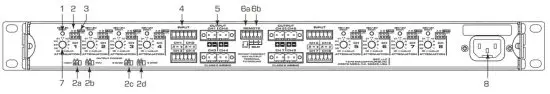
| 1. Signal / Protect / Limit LED (one per channel) Signal=Green, Limit=Orange, Protect=Red, Standby=Off • After 25 minutes with no signal, that channel will go into standby mode. |  |
| 2. DIP Switch output configuration (A Bone pair per channel) a. 100 V Setting b. 70 V Setting c. 8 Ω Setting d. 4 Ω Setting |  |
| 3. High-pass Filter – 80 Hz (On/Off – one per channel) • High-pass Filter On • High-pass Filter Off | 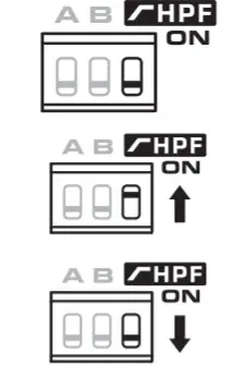 |
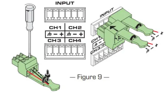
| 4. Input – one per channel • Ground, Negative, Positive • Balanced / Unbalanced • 3.5 mm Euro, 3-pin (green) | 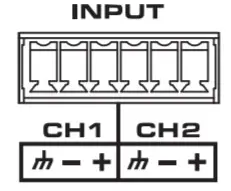 |
| 5. Output – one per channel • Configurable with DIP switches • Negative, Positive pins • 5.0 mm Euro, 4-pin, one for every 2 outputs (green) • Class 2 Wiring | 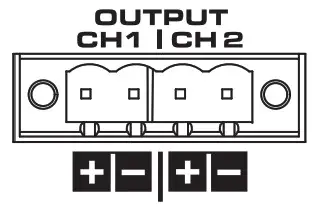 |
| 6. Remote • Provides remote control of the standby mode of the amplifier • Provides an indication of standby status of the amp | 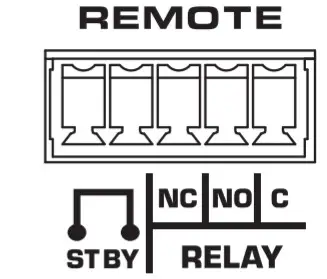 |
| • Standby – attach a switch to the two STBY pins. » When the switch is open, the amplifier is not in standby – unless it was put in standby for another reason. » When the switch is closed, the amplifiers in standby. Not Standby Standby | 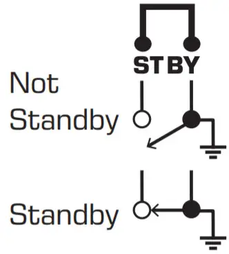 |
| • Relay Contacts » When the amplifier is operating normally(passing audio), the relay is energized. » When the amplifier is in a non-operating mode (standby etc), the relay is not energized. | 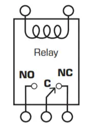 |
| 7. Attenuation Knob – (one per channel) • Attenuates from +4 dBu to infinity (off) • Use small flat-tip screwdriver to adjust | 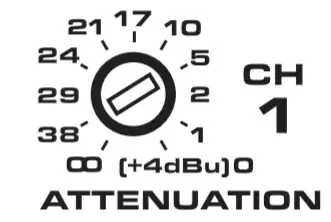 |
| 8. AC Mains • 100–240 V ~ 50/60 Hz | 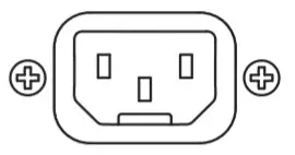 |
Connections
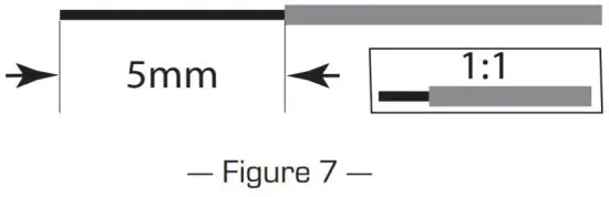
Wiring
- For all wiring
- Strip Length = 5mm See Figure 7.
- DO NOT TIN!
![]() IMPORTANT!: Class 2 Wiring on all outputs.
IMPORTANT!: Class 2 Wiring on all outputs.
Outputs 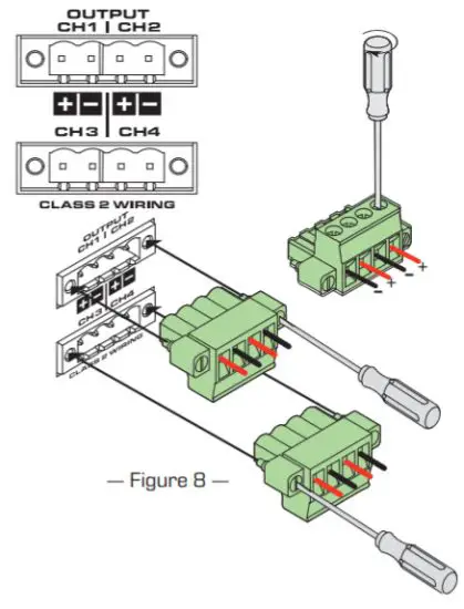
![]() IMPORTANT!: Class 2 Wiring on all outputs
IMPORTANT!: Class 2 Wiring on all outputs
- One for each channel
- 3.5 mm Euro, 4-pin (green)
MP-A20V (1x)
MP-A40V (2x)
MP-A80V (4x)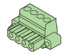
![]() CAUTION!: Do not connect any output to the ground.
CAUTION!: Do not connect any output to the ground.
The outputs are configured individually for the application intended for that particular output. DIP switches are provided to perform the configuration. The amplifier uses the DIP switch settings to set the power requirements. Make sure the switches match the configuration.
The DIP switches are located up and to the right of the associated channel attenuation knob. In addition, there is a chart on the rear panel of the amplifier with the setting information.
The output power settings use DIP switches labeled A and B.
| 100 V Setting – both DIP switches are in the down position. Use this setting when you have multiple loudspeakers on one channel. Make sure the loudspeaker’s transformer is set to 100V. | |
| 70 V Setting – DIP switch A is up, B is down. Use this setting when you have multiple loudspeakers on one channel. Make sure the loudspeaker’s transformer is set to 70V. | |
| 8 Ω Setting – DIP switch A is down, DIP switch B is up. | |
| 4 Ω Setting – both DIP switches are in the up position. | |
| 80 Hz High-pass Filter On – The HPF switch is in the up, or on position. (the proper setting for most 70 V and 100 V systems) | |
| 80 Hz High-pass Filter Off – The HPF switch is in the down, or off position. |
Inputs
Refer to Figure 9
- One Input for each Channel
- 3.5 mm Euro, 3-pin (green – one for each Input)
- Cable Tie (one for each input)
 MP-A20V (2x)
MP-A40V (4x)
MP-A80V (8x)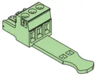
MP-A20V (x2)
MP-A40V (x4)
MP-A80V (x8)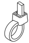
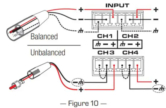
Balanced or Unbalanced
Refer to Figure 10
- Balanced inputs require three wires: ground, negative, and positive.
- Unbalanced requires a jumper between the ground pin and the negative pin.
Input Levels
Input sensitivity: 1.23 V (+4 dBu) Is the input level you must supply with the attenuation knob at minimum attenuation (fully clockwise) to achieve the rated output
power.
Maximum input level: 12.3 V (+24 dBu) Is the level at which the input stage of the amplifier is overloaded and the signal begins to clip.
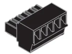
Remote
Remote provides the capability of controlling and monitoring the status of the amplifier from a remote location. Figure 11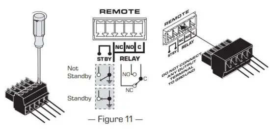
- One per amplifier
- 3.5 mm Euro, 5-pin (black)
Standby
- Connect the two STBY pins on the REMOTE connector to the two pins of a toggle switch.
- When the switch is open, the amplifier is not in standby.
NOTE: If the amplifier is on standby because of a no-signal time-out, in protected mode, or off, closing and opening the switch has no effect on the amplifier status. 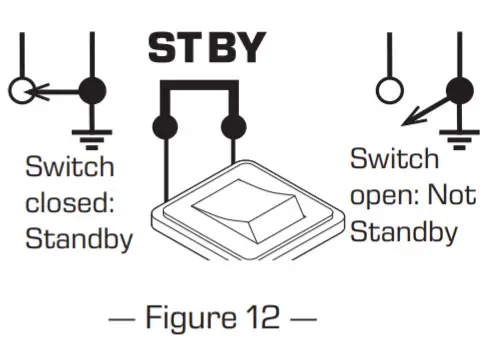
- When the switch is closed, the amplifier goes into standby.
Relay
The REMOTE RELAY provides a means to monitor the amplifier’s operating condition with external equipment. Figure 13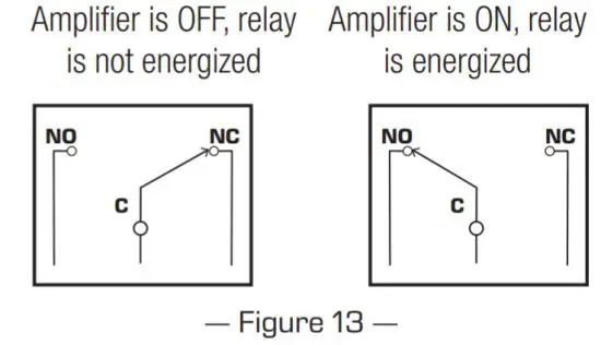
- NO = Relay “normally open” terminal
- C = Relay “common” terminal
- NC = Relay “normally closed” terminal
- Amplifier Fault/Standby/Off = Relay NOT Energized, C & NC terminals connected
- Amplifier OK = Relay Energized, C & NO terminals connected
The only items where the relay is de-energized are conditions such as: - Power OFF (e.g. unplugged)
- Amp initial power on a.k.a “boot” (very brief)
The Following require signal at the input to indicate a fault & de-energize the relay; - Over-current protection
- Amp Output DC fault
- Thermal shut down
Other internal faults that result in shutdown via protection circuitry, but leave housekeeping voltages operational![]() IMPORTANT!: Nominal switching capacity is 30 VDC at 1 A for a total of 30 W maximum. The maximum voltage is 220 VDC if the current is limited to observe the maximum power rating (30 W).
IMPORTANT!: Nominal switching capacity is 30 VDC at 1 A for a total of 30 W maximum. The maximum voltage is 220 VDC if the current is limited to observe the maximum power rating (30 W).
Dimensions
Specifications
| Model | MP-A20V | MP-A40V | MP-ABOVE | ||||
| Channels | 2 | 4 | 8 | ||||
| Power (all channels driven) | |||||||
| 40 | 200 W | 200 W | 200 W | ||||
| 80 | 200 W | 200 W | 200 W | ||||
| 70 V | 200 W | 200 W | 200 W | ||||
| 1 00 V | 200 W | 200 W • | 200 W • | ||||
| FlexAmp Technology | Allows each pair of amplifier channels to deliver up to 400 W total power, in any ratio | ||||||
| Typical distortion (4-8 0) | < 0.01% | ||||||
| Maximum distortion (4-8 0) | < 1% | ||||||
| Damping factor | 100 | ||||||
| Output circuitry | Class D | ||||||
| Protection | Short circuit, open circuit, over current. thermal, RF protection, DC fault inrush limiting | ||||||
| Gain at 80 | 30 dB | ||||||
| Input impedance | > 10k balanced or unbalanced | ||||||
| Input sensitivity | 1.23 V (+4 di3u) | ||||||
| Maximum input level | 12.3 V (+24 dBu) | ||||||
| Frequency response at 8 0 | 20 Hz — 20 kHz +/- 0.5 dB | ||||||
| Signal to noise | > 103 dB | ||||||
| User-configurable operating modes (per channel) | DIP switch selectable low impedance 4 0 or 8 0, high impedance direct drive 70 V or 100 V | ||||||
| ugh-pass filter | 80 Hz DIP switch engaged per char ml | ||||||
| Remote Relay | |||||||
| Nominal switching capacity | 30 VDC at 1 A for a total of 30 W maximum. | ||||||
| maximum voltage | 220 VDC if the current is limited to observe the maximum power rating (30W). | ||||||
| Cooling | |||||||
| Type | Forced air cooling, thermally regulated fan speed, side/rear-to-front airflow | ||||||
| Operating temperature range | Maximum: -10° – 50° C, recommended. 0° – 35° C, performance may be reduced above 40° C | ||||||
| Connectors | |||||||
| Input correctors | Two 3.5 mm Euro, 3-pin (green) | Four 3.5 mm Euro, 3-pin (green) | Eight 3.5 mm Euro, 3-pin (green) | ||||
| Remote connectors | One 3.5 mm Euro, 5-pin (black) | One 3.5 mm Euro, 5-pin (black) | One 3.5 mm Euro. 5-pin (black) | ||||
| Output connectors | One 5.0 mm Euro. 4-pin (green) | Two 5.0 mm Euro, 4-pin (green) | _ Four 5.0 mm Euro, 4-pin (green) | ||||
| Front panel indicators | Power. signal (per channel), limit / mute / protect (per channel) | ||||||
| Rear panel indicators | Bi-Color LED signal / limit / mute / protect | ||||||
| Remote VO | Remote standby, amplifier status indication on one 3.5 mm Euro, 5-pin (black) | ||||||
| AC Paver Input | Universal power supply with PFC, 100-24 OVAC, 50 – 60 Hz | ||||||
| Agency approvals | lit. CE. RoHS/WEEE compliant FCC Class B (conducted and radiated emissions) | ||||||
| Dimensions (HWD) inches | 1.75 in x 19 in x 14.84 in | ||||||
| Dimensions (HWD) mm | 44 mm x 483 mm x 377 mm | ||||||
| Net weight | 7.7 lb (3.5 kg) 9.3 lb (42 kg) 1 13.9 lb (6.3 kg) | 12.8 lb (5.8 kg) | |||||
| Shipping weight | 12.3 b (5.6 kg) | 1 7.4 lb (7.9 kg) | |||||
Notes:
| Contact QSC QSC, LLC 1675 MacArthur Boulevard Costa Mesa, CA 92626-1468 USA Main Number: +1.714.754.6175 Toll-Free 800.854.4079 (US Only) Website: www.qsc.com | Sales and Marketing: +1.714.957.7100 or toll-free (the USA only) 800.854.4079 FAX: +1.714.754.6174 E-mail: [email protected] | QSC Technical Service +1.714.957.7150 or toll free (USA only) 800.772.2834 FAX: +1.714.754.6173 E-mail: [email protected] |
© 2018 QSC, LLC. All rights reserved. QSC and the QSC logo are registered trademarks of QSC, LLC in the U.S. Patent and Trademark office and other countries. FlexAmp is a trademark of QSC, LLC. All other trademarks are the property of their respective owners.
http://patents.qsc.com.


