
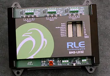
RLE Technologies BMS-WiNG Wireless Sensor
Installation Supplies
Included with the BMS-LD3Z
BMS-LD3Z device
Available from RLE, sold separately
24VDC power adapter Leak detection cable, LC-KITs, and spot detectors as necessary for your application
Additional Supplies
18AWG shielded twisted pair stranded copper wire – no more than 2000ft (610m) (Modbus RTU or BACnet MS/TP communication via RS-485 port)
Mount the Device
The BMS-LD3Z is designed to be installed in a panel, on a DIN rail, or mounted on a wall.
- If you’re installing it on a DIN rail, use the DIN rail clip and secure the unit appropriately for your application.
- If you’re mounting the unit on a wall, use a screwdriver to loosen the three screws and remove the DIN rail clip from the back of the unit. Then use the keyhole slots and secure the unit to the wall.
Power the Unit
The BMS-LD3Z is designed to accept hardwired 24VDC power through the power terminal block (TB2). If hardwired power is not available, purchase and install RLE’s PSWA-DC-24 power supply.
Leak Detection Sensing Cable
Since leak detection sensing cable cannot connect directly to a controller, a leader cable is used to connect each separate zone of leak detection cable to the BMS-LD3Z. For each zone of leak detection:
- Insert the stripped wires of the leader cable into the appropriate slots in the terminal block – from left to right: white, black, green, red. Tighten the screws to secure the wires.
- Unscrew the EOL from the end of the leader cable.
- Attach the length of sensing cable to the leader cable.
- Route the sensing cable according to your cable layout
- Secure the EOL to the unoccupied end of the sensing cable.
- Repeat steps 1-6 for each zone of leak detection.
Set the DIP Switches
The BMS-LD3Z has two sets of DIP switches. Push the numbered switch to the right to turn it on; push the switch to the left to turn it off. DIP switch 1 is used for system and communications configuration. DIP switch 2 is used to set the unit’s device address.
| DIP Switch 1, switches 1 through 8 | ||
| SW1 and SW2 – Set the baud rate for the EIA-485 Port – 8 bit, no parity, 1 stop bit. | ||
| 1 = Off | 2 = Off | 9600 baud |
| 1 = On | 2 = Off | 19200 baud |
| 1 = Off | 2 = On | 38400 baud |
| 1 = On | 2 = On | 76800 baud |
| SW3 – Modbus RTU or BACnet MS/TP Selection | ||
| 3 = Off | Communication via BACnet MS/TP | |
| 3 = On | Communication via Modbus RTU | |
| SW4 – Modifiable BACnet Instance (For advanced users only) | ||
| 4 = Off | BACnet instance set via DIP switch SW2 (default) | |
| 4 = On | BACnet instance set from the command line. Refer to the BMS BACnet Instance Modification Technical Guide for complete instructions. | |
| SW5 – Zone 1 Leak Detection – Enable or disable leak detection for Zone 1. | ||
| 5 = Off | Leak detection is enabled. (Default) | |
| 5 = On | Leak detection is disabled. | |
| SW6 – Zone 2 Leak Detection – Enable or disable leak detection for Zone 2. | ||
| 6 = Off | Leak detection is enabled. (Default) | |
| 6 = On | Leak detection is disabled. | |
| SW7 – Zone 3 Leak Detection – Enable or disable leak detection for Zone 3. | ||
| 7 = Off | Leak detection is enabled. (Default) | |
| 7 = On | Leak detection is disabled. | |
| SW8 – Leak Alarm Delay – The amount of time that elapses between the time a leak is detected and when that leak is annunciated. | ||
| 8 = Off | 10 seconds (Default) | |
| 8 = On | 120 seconds | |
Use DIP switch 2 to set the address of the device. This should be a number between 1 and 254. Adjust the individual switches until their sum equals the device address. Switch values are as follows: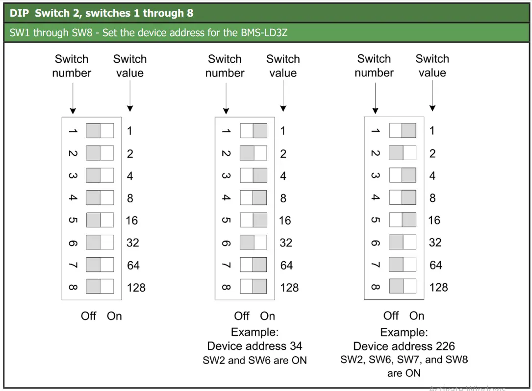
Connect the BMS-LD3Z to the Network
The BMS-LD3Z needs network connectivity to communicate with a Modbus RTU or BACnet MS/TP system, such as a BMS. Use a 2-wire RS-485 cable to connect the BMS-LD3Z to the network through the wiring connection at TB1. RLE recommends an 18AWG shielded twisted pair stranded copper wire for the connection, using no more than 2000 feet (609.6m) of wire at this specification. If longer runs are needed, please contact RLE.
CLI
After the BMS-LD3Z is connected to the terminal (115200 bps, 8 bit, no parity 1 stop bit) you’ll see a menu that can be used to help understand the BMS-LD3Z’s settings and functionality. Commands available from this menu are:
| Command | Action |
| slist | List all sensors |
| settings | Show current system settings (set by dip switches) |
| bid | Show BACnet device ID in use |
| sbid | Configure custom BACnet device ID |
| reboot | Reboot unit |
| ? | Print main menu |
Modbus Communications
The BMS-LD3Z uses its RS-485 port to communicate via Modbus. The BMS-LD3Z is configured to act as a Modbus Server device on a common network and is a Server only device – it will never initiate a communications sequence.
Read Registers
To read the BMS-LD3Z’s parameter values, the Client must send a Read Registers request packet (function code 03 or function code 04).
| Register | Name | Description | Units | Range |
| 30001 | Status | Bit Level Status – as follows: 0x01 (1) = Zone 1: Leak Detected 0x02 (2) = Zone 2: Leak Detected 0x04 (4) = Zone 3: Leak Detected 0x100 (256) = Zone 1: Fault Detected 0x200 (512) = Zone 2: Fault Detected 0x400 (1024) = Zone 3: Fault Detected | None | 0-65535 |
| 30002 | Leak Current Zone 1 | Leakage current on cable | μAmps | 0-65535 |
| 30003 | Leak Current Zone 2 | Leakage current on cable | μAmps | 0-65535 |
| 30004 | Leak Current Zone 3 | Leakage current on cable | μAmps | 0-65535 |
| 30010 | Version | Firmware version | xx.xx X 100 | 0-65535 |
| 40009 | Number of Zones (3) |
BACnet Communications
BACnet auto-discovery can be used to find all BACnet data points available for the 1-wire sensors. BACnet MS/TP objects are as follows:
| Object | Description | Object | Description |
| BI:X01 | Zone X Enabled | ||
| BI:X02 | Zone X Leak Detected | AI:X02 | Zone X Leakage Current |
| BI:X03 | Zone X Cable Break |
Directions for modifying the BACnet instance, intended for advanced users, can be found in the BACnet Instance Modification Technical Guide.
System Reference
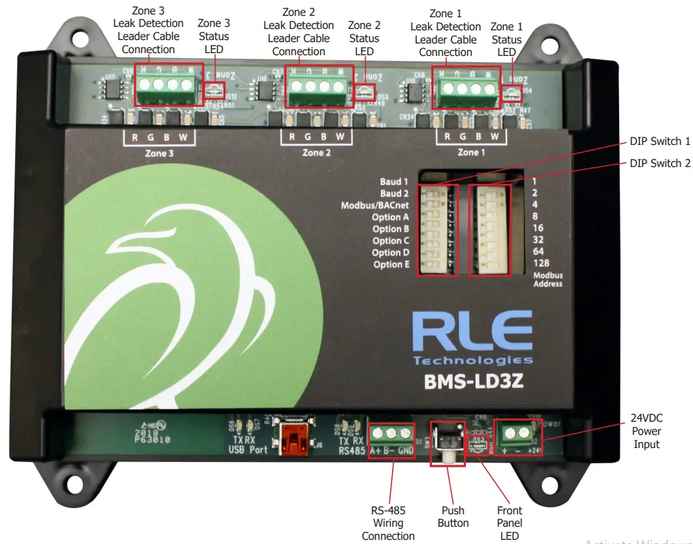
Front Panel LED
The lower right corner of the BMS-LD3Z houses an LED that uses different colors and blink patterns to convey device status and information.
Leak Detection Zone Status LEDs
The LEDs next to the three leak detection leader cable connectors across the top of the device light to indicate the leak zone’s status: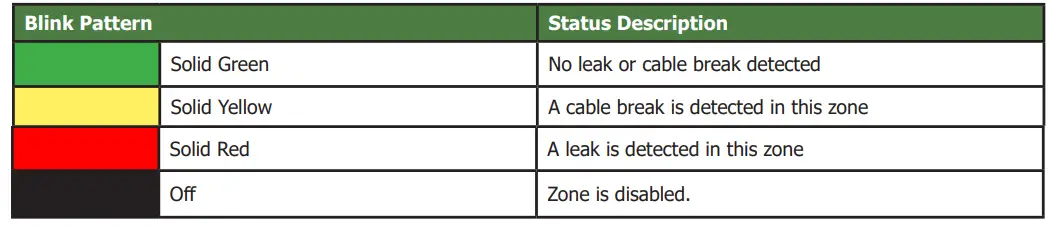
Front Panel Push Button
A white button in the lower right corner of the BMS-LD3Z can be used to perform a factory reset of the device:
| Operation | Function |
| Press and hold for 20 seconds, then release the button (Red LED will turn ON after 10 seconds and then turn OFF after an additional 10 seconds) | Perform a full factory reset of the unit. Any stored BACnet settings will be deleted. |
BMS-LD3Z Physical Diagram
Troubleshooting
Sensors Are Not Associating With the BMS-WiNG
If an installed sensor is not detected by the BMS-WiNG, it is either too far away from the BMS-WiNG or there is an obstruction in its path. To determine the source of the problem, remove the sensor from its installed location and place it near the BMS-WiNG. If it’s then discovered by the BMS-WiNG:
- Its desired location may be too far away. Move the sensor away from the BMS-WiNG in small increments. This will help you determine the distance threshold of the sensor.
- An obstruction is blocking the signal. Move the sensor.
- The sensor has a wire whip antenna that can be extended out of the sensor case in an effort to resolve either a distance limitation or obstruction issue. To expose the whip antenna:
- Access the sensor’s circuit board. Hold the sensor upside down in your hand (label toward your palm) and squeeze the short side of the sensor enclosure’s lid. Pull the base away to open the sensor enclosure. The sensor board should remain in the lid. Gently grasp the edges of the sensor lid and
pull it to free it from the sensor enclosure. - Locate the whip antenna connection on the circuit board. Gently rotate the connection 180° so the antenna routes toward the U3 marking on the board, instead of routing past the Y1 marking on the board.
- Now put the board back into the enclosure. The whip antenna will route out the vent hole in the enclosure near the tip of the orange wing icon on the enclosure label, and the sensor board will slip into the board slots in the enclosure. The whip antenna should extend directly out of the enclosure and not pass back over the length of the board. Reapply the sensor base.
- You should end up with about three inches of antenna outside of the enclosure, and this can dramatically increase the signal distance the sensor can achieve.
- Access the sensor’s circuit board. Hold the sensor upside down in your hand (label toward your palm) and squeeze the short side of the sensor enclosure’s lid. Pull the base away to open the sensor enclosure. The sensor board should remain in the lid. Gently grasp the edges of the sensor lid and
If the sensor is still not discovered by the BMS-WiNG:
- Verify the sensor’s serial number. Make sure you’re looking for the correct sensor at that position.
- Remove the sensor’s cover and make sure the battery pull tab has been completely removed.
- Check to see that the heartbeat LED is blinking, once every 10 to 20 seconds.
- If the LED is not blinking, ensure there is not a gap between the battery clips and the side of the battery. Remove the battery, gently squeeze the clips in, and replace the battery.
- Check the battery’s voltage. If the battery is reading a low voltage (lower than 2.7V), replace the battery with a 3.6V lithium AA battery.
Sensor Battery Issues
- When you replace the battery, replace it with a 3.6V lithium battery. WiNG sensors
- will NOT operate with a standard alkaline AA cell.
- Make sure you replace the battery with the terminals facing the correct direction.
- The sensor will not function if the battery is inserted backwards.


 Device User Manual")

 Device Instructions")


