resideo PROSIXLCDKP-EU Series Wireless Keypad
Installation and Setup Guide
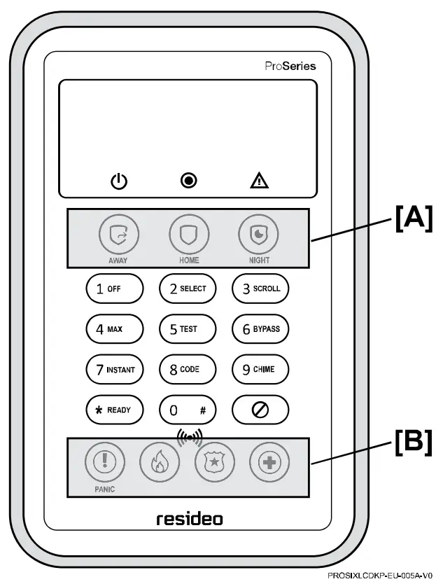
The PROSIXLCDKP-EU is a wireless keypad for use with Control Panels that support SiX™ series devices. Up to eight (8) Keypads per partition can be used on the system.
Note: Installation shall be done in accordance with local regulations.
| Item/Key | Function |
| Display Window | Liquid Crystal Display (LCD) displays protection point identification, system status, and messages. |
 | Power LED |
 | System Status LED |
 | System Trouble LED |
| Arm Away key |
| Arm Home (Stay) key |
| Arm Night (Stay) key |
| Off key |
| Select key |
|
|
| Arm (Away) Maximum key (no entry delay) |
| System Test key |
| Bypass Zone key |
| Arm (Home) Instant key (no entry delay) |
| Add Security Codes key |
| Chime Mode key |
| Check Zones key |
 | Disarm/Cancel Key |
 | Prox Tag reader (RFID) |
 | Panic Alarm key |
 | Panic key + Fire Panic key |
 | Panic key + Police Panic key |
 | Panic key + Medical Panic key |
Keys 0 – 9 | Numeric keys used to enter security code(s). |
 AWAY
AWAY HOME
HOME NIGHT
NIGHT OFF
OFF SELECT
 SCROLL
 MAX
MAX TEST
TEST BYPASS
 INSTANT
 CODE
CODE CHIME
CHIME READY
READY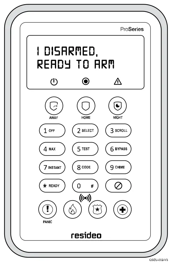
KEYPAD OPERATION
For operating instructions, refer to the Control Panel instructions.
| LEDs | Off | Red – Steady | Green – Steady | Red – Flashing | |
| POWER | Battery – OK | Battery – Low | ||
| STATUS | Not Ready to Arm | Armed | Ready to Arm | Alarm Detected |
| TROUBLE | No Trouble Present | System Trouble Present | — | Device Trouble Present |
| Note: When the system is in Programming Mode, the Trouble and Status LEDs alternately flash Red and Green. | |||||
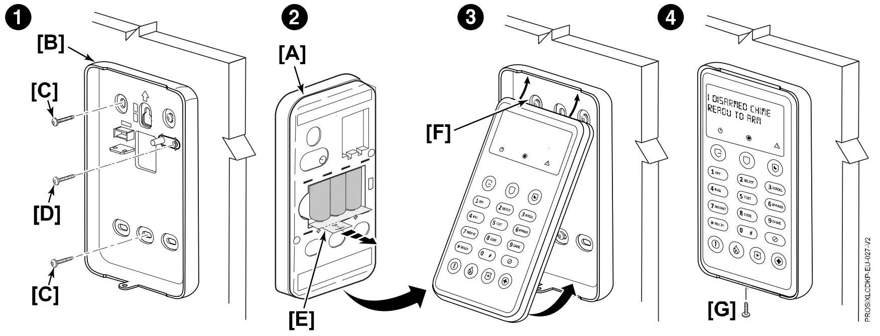
KEYPAD MOUNTING
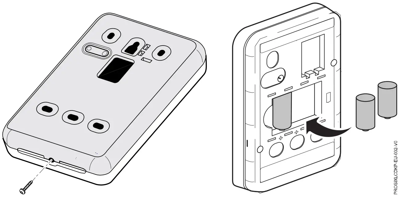
The keypads can be surface mounted directly to a wall as follows:
- Separate the keypad front panel [A] to the rear mounting plate [B].
- Mount the mounting plate to the wall using the screws [C]. Insert the tamper screw [D] as shown.
Note: Mounting screws not provided. Use 3.5mm – 4mm wood screws (with plastic wall anchors, if necessary). - Pull out the battery activation tab [E] from the back of the keypad front panel.
- Align the case with the cleats [F] and snap into place and secure with bottom screw [G] (provided).

ENROLLING KEYPAD
The keypad must be enrolled in the Control Panel before it can be used. Registration and programming are conducted through the AlarmNet 360™ cloud-based management platform. After accessing the customer account, perform the following steps.
- Select “KEYPADS”.
- Select “ADD KEYPAD”.
- Select “LEARN” and wait for the Control Panel to be in learning mode.
- Activate the keypad by pressing any key:
• The keypad automatically attempts to pair with the Control Panel.
• The top three status LEDs [A] and bottom four Panic keys [B] will come on (red).
• If enrollment is not successful, press any of the keys on the keypad to restart the pairing process or remove and reinstall batteries. - After a successful pairing, the keypad’s LCD display will turn off, and the three status LEDs [A] and four Panic keys will [B] will turn off a few seconds later to confirm the pairing.
- After enrollment, program and save the keypad’s zone options (zone descriptor, etc.)

Note: Make sure to assign a descriptor to the keypad for easy identification when keypad events occur.
IMPORTANT: After enrolled, the keypad cannot be used with another Control Panel until it is un-enrolled (deleted) from the current panel through the AlarmNet 360™ cloud-based management platform.
Note: For detailed programming instructions refer to the Installation Instructions for the Control Panel with which this device is used.
AUTHENTICATING KEYPAD USER
For security purposes, a user (or installer) of the keypad must be authenticated prior to being able to access/view any of the keypad displays. To authenticate a user, perform the following steps.
Note: Nothing will be displayed, even if the system is armed, until a valid PIN (or Prox Tag) is entered + press any key.
- At the keypad, enter the PIN (or swipe the Prox Tag) for the user.
- After a successful authentication, enter the 4/6-digit code +

• The system is disarmed and alarm sounding is silenced.
• To clear the memory of alarm display (if present), enter 4/6-digit code + again.
PANIC ALARM KEYS
This keypad features three Emergency Panics for 24- hour silent, audible, fire or medical / personal alarms. These emergency Panic keys may be programmed for Fire, Police, and Medical alarms. Panic activation requires a 2-button sequence. After the first button in the sequence is pressed, you can cancel the emergency by pressing any key other than one of the Panic keys.
Note: Only the Audible Alarm option can be used as a holdup alarm.
There are 3 ways to generate an emergency Panic alarm:
|
|
| |
| |
|
 Panic
PanicKEYPAD PROGRAMMING MODE
This mode displays keypad programmed information and provides access to Default and Reset options. Enter the INSTALLER code +1 to disarm. Press and hold the “3” key for 2 seconds to enter PROGRAMMING mode. The system will exit PROGRAMMING mode after 10 seconds of inactivity. Press the “3” key to scroll or “*” key to exit.
| Display | Meaning/Option | Display | Meaning/Option |
| App: / Boot: | Displays the keypad’s current App and Boot versions | Partition= / Keypad ID= | Displays Partition assignment and Keypad ID programmed in the control panel. |
| RF6: | Displays the keypad’s SiX software version and the keypad MAC ID | Reset Keypad | Prompts to Reset Keypad. 2=CONFIRM (restart) |
| Default Keypad | Prompts to Default Keypad. 2 = CONFIRM to remove keypad from control panel. Note: If the keypad is repowered within 24 hours, it will re-pair with the control panel. After 24 hours, it will need to be re-enrolled. | A: None | (Future Use) |
| B: None | (Future Use) | ||
BATTERY REPLACEMENT
- At the bottom of the keypad, remove the screw that secures the front cover to the rear mounting bracket.
- Remove the batteries, wait 10 seconds, then insert three new 3V Lithium batteries (see Specifications for replacement batteries).
- Align the case with the cleats and snap into place and secure with bottom screw.

BATTERY CAUTION: Risk of fire, explosion, and burns. Do not recharge, disassemble, heat above 55°C, or incinerate. Dispose of used batteries properly. Keep away from children.
Note: Constant exposure to high or low temperature or high humidity may reduce battery life.
SPECIFICATIONS
Dimensions (mm) / Weight: 161 (H) x 97 (W) x 34 (D) / 285 g
RF Frequency: 2.4GHz (<20 dBm)
Batteries: Three (3) – 3V Lithium:
• EVE CR-123A
• Panasonic CR123A
• Duracell DL123A
Tamper: Wall (audible alert and signal sent to Control Panel)
Sounder: Piezoelectric

 The product should not be disposed of with other household waste. Check for the nearest authorized collection centers or authorized recyclers. The correct disposal of end-of-life equipment will help prevent potential negative consequences for the environment and human health.
This system must be checked by a qualified technician at least once every three (3) years.
Any attempt to reverse-engineer this device by decoding proprietary protocols, de-compiling firmware, or any similar actions is strictly prohibited.
REFER TO THE INSTALLATION INSTRUCTIONS FOR THE CONTROL WITH WHICH THIS DEVICE IS USED, FOR DETAILS REGARDING LIMITATIONS OF THE ENTIRE ALARM SYSTEM.
SUPPORT & WARRANTY INFORMATION
For the latest documentation, warranty, and support, please go to: www.resideo.com

![]() Sécurité Communications SAS (SECOM) 1198, Avenue du Docteur Maurice Donat 06250 Mougins – FRANCE
Sécurité Communications SAS (SECOM) 1198, Avenue du Docteur Maurice Donat 06250 Mougins – FRANCE
 Ademco 1 Ltd., 200 Berkshire Place Winnersh Triangle, Berkshire, RG41 5RD – UNITED KINGDOM
Customer Support
© 2022 Resideo Technologies, Inc.
www.resideo.com


 Installation Guide")


