ACV 130 Smart Green Instruction Manual
General Recommendations
NOTES
This manual contains important information with respect to the installation, the starting up and the maintenance of the appliance.
This manual must be provided to the user, who will read it carefully and keep it in a safe place.
We accept no liability should any damage result from the failure to comply with the instructions contained in this technical manual.
![]() Essential recommendations for safety
Essential recommendations for safety
- It is strictly prohibited to carry out any modifications to the appliance without the manufacturer’s prior and written agreement.
- The product must be installed by a qualified engineer, in accordance with applicable local standards and regulations.
- The installation must comply with the instructions contained in this manual and with the standards and regulations applicable to domestic hot water tanks.
- Failure to comply with the instructions in this manual could result in personal injury or a risk of environmental pollution.
- The manufacturer declines all liability for any damage caused as a result of incorrect installation or in the event of the use of appliances or accessories that are not specified by the manufacturer.
![]() Essential recommendations for the correct operation of the appliance
Essential recommendations for the correct operation of the appliance
- In case of anomaly, please call your installer for advice.
- Faulty parts may only be replaced by genuine parts.
- Our water heaters are designed and manufactured for the exclusive purpose of heating and storing domestic hot water.
- The domestic hot water heaters must only be heated using hot water in a closed circuit.
![]() General remarks
General remarks
- The availability of certain models as well as their accessories may vary according to markets.
- The manufacturer reserves the right to change the technical characteristics and features of its products without prior notice. Please check for an updated version of this manual on the website www.acv.com.
- The part number (P/N) and serial number (S/N) of the appliance are indicated on its rating plate and must be provided to ACV in case of warranty claim. Failure to do so will make the claim void.
- In spite of the strict quality standards that ACV applies to its appliances during production, inspection and transport, faults may occur. Please immediately notify your approved installer of any faults.
Product Information
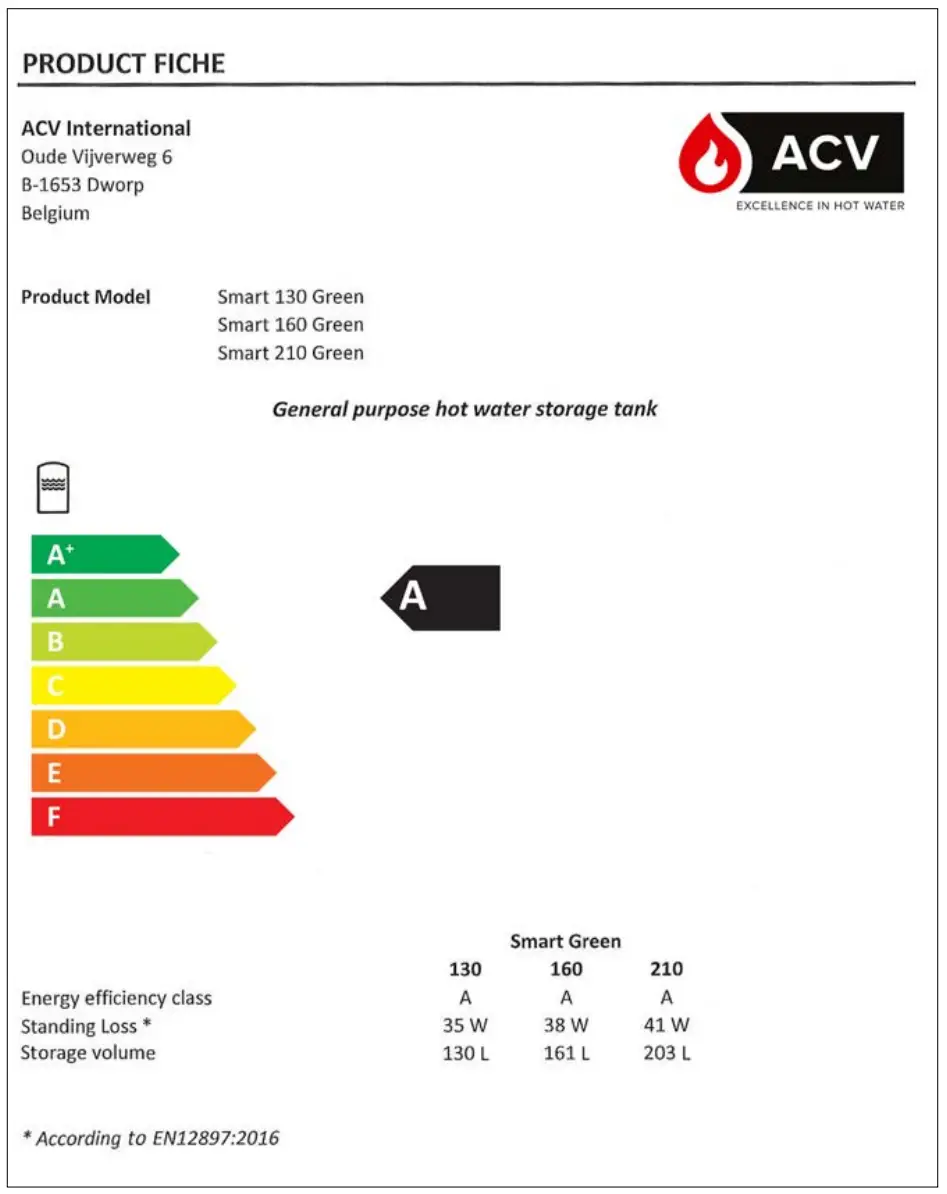
ENERGY LABELLING
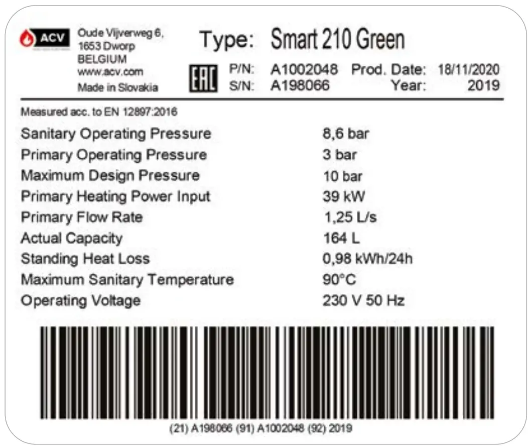
RATING PLATE
Appliance Description
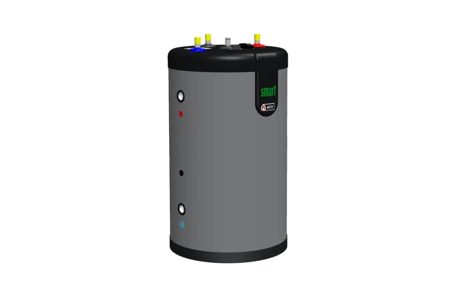
MODELS – Smart 130 – 160 – 210 Green
“Smart Green” is a floor-standing hot water storage tank that operates within a heating system. Based on the ACV tank-in-tank design, this Energy Label A tank uses high performance insulation technology, for minimized standing loss and improved energy efficiency.
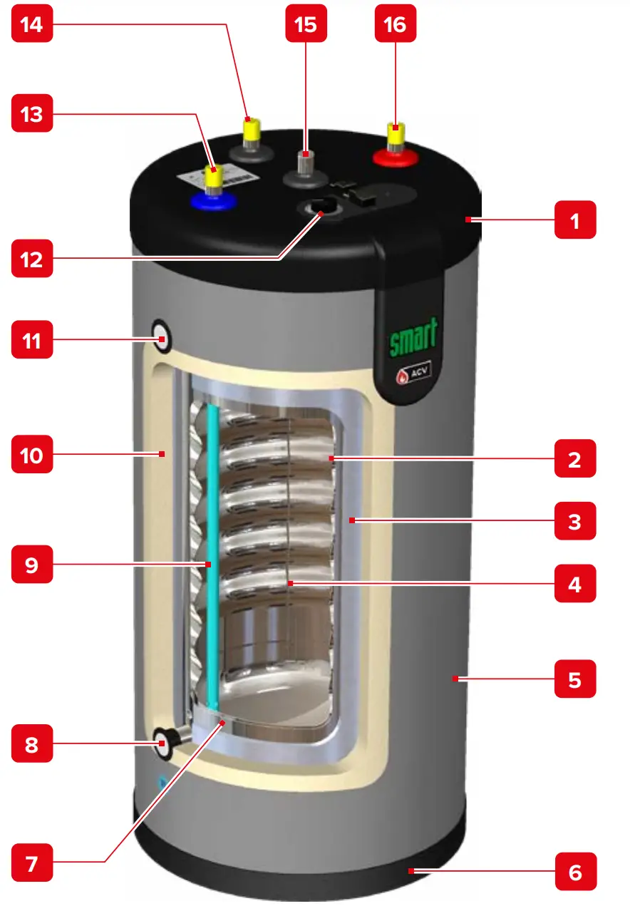
- Polypropylene top lid
- Stainless steel tank (DHW)
- Vacuum insulation panel
- Dry well
- Polypropylene shell
- Polypropylene bottom lid
- Outer steel tank (primary circuit)
- Return connection (primary circuit)
- Dip tube
- Polyurethane foam insulation
- Flow connection (primary circuit)
- Control thermostat (60-80°C)
- Cold water inlet connection
- Auxiliary DHW connection
- Manual air bleed valve
- Hot water outlet connection
Technical Characteristics
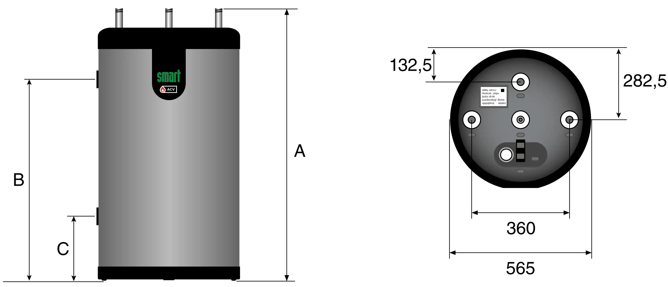
DIMENSIONS AND MAIN CHARACTERISTICS
Tank dimensions | Smart Green | |||
| 130 | 160 | 210 | ||
| A | mm | 1025 | 1225 | 1497 |
| B | mm | 760 | 960 | 1232 |
| C | mm | 235 | 235 | 235 |
| Empty weight | Kg | 55 | 65 | 75 |
| Main characteristics | Smart Green | |||
| 130 | 160 | 210 | ||
| Total capacity | L | 130 | 161 | 203 |
| Primary capacity | L | 31 | 35 | 39 |
| DHW capacity | L | 99 | 126 | 164 |
| Primary connection [F] | “ | 1 | 1 | 1 |
| DHW connection [M] | “ | ¾ | ¾ | ¾ |
| Auxiliary DHW loop connection [M] | “ | ¾ | ¾ | ¾ |
| Primary pressure drop* | mbar | 26.8 | 26.8 | 41.6 |
| Heating surface area | m2 | 1.26 | 1.54 | 1.94 |
| Max Design Pressure* | bar | 10 | 10 | 10 |
| Reheat Performance – Primary Heating Power Input* | kW | 24.7 | 32.2 | 39.2 |
| Primary flow rate (to achieve Reheat Performance) * | L/sec. | 0.70 | 0.70 | 1.25 |
| Reheat time* | min | 10 | 10 | 9 |
| Standing Heat Loss* | kWh/24h | 0.84 | 0.91 | 0.98 |
| W | 35 | 38 | 41 | |
* According to EN12897:2016
| Main characteristics | Smart Green | |||
| 130 | 160 | 210 | ||
| Max. operating pressure – primary | bar | 3 | 3 | 3 |
| Max. operating pressure – DHW | bar | 8.6 | 8.6 | 8.6 |
| Supply pressure (DHW circuit) | bar | 6 | 6 | 6 |
| Maximum temperature – heating side | °C | 90 | 90 | 90 |
| Maximum temperature – DHW side | °C | 80 | 80 | 80 |
| Water quality |
| |||
ELECTRICAL CHARACTERISTICS
Main characteristics | Smart Green | |||
| 130 | 160 | 210 | ||
| Rated voltage | V~ | 230 | 230 | 230 |
| Rated frequency | Hz | 50 | 50 | 50 |
| Max. Amp rating | A | 6 | 6 | 6 |
Wiring diagram
- Control thermostat [60-80°C]
- Circulator pump [option]
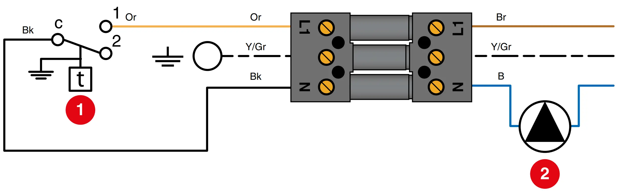
B. Blue
Bk. Black
Br. Brown
G. Grey
Or. Orange
W. White
Y/Gr. Yellow/Green
PERFORMANCE
DHW performance* | Smart Green | |||
| 130 | 160 | 210 | ||
| Peak flow at 45 °C | L/10′ | 275 | 348 | 469 |
| Peak flow at 60 °C | L/10′ | 161 | 209 | 272 |
| Peak flow first hour at 45 °C | L/60′ | 911 | 1156 | 1560 |
| Peak flow first hour at 60 °C | L/60′ | 549 | 689 | 913 |
| Constant flow at 45 °C | L/h | 763 | 970 | 1309 |
| Constant flow at 60 °C | L/h | 465 | 576 | 769 |
* Conditions: Primary circuit temp.: 85°C – ΔT: 10°C – Water supply temp.: 10°C
Installation
SAFETY INSTRUCTIONS
![]() General remarks
General remarks
- Connections (electrical, hydraulic) must be carried out in accordance with applicable standards and regulations.
- If the water drawing off point is far from the tank, installing an auxiliary DHW loop can allow to get hot water more quickly at all times.
![]() Essential instructions for the correct operation of the system
Essential instructions for the correct operation of the system
- The tank must be installed in a dry and protected area.
- nstall the appliance to ensure easy access at all times.
- To avoid any risk of corrosion, connect the stainless steel tank directly to the earth. Use an adjustable earth clamp (see example below) on one of the DHW connections to connect to the earth. Advised copper wire section: 2.5mm².

- Make sure to install a pressure reducing valve set at 4.5 bar in the DHW circuit if the supply pressure is higher than 6 bar.
- On the DHW circuit, install an approved safety group, comprised of a safety valve set at 7 bar, a check valve and a stop valve.
- Make sure that the outlet of the safety unit goes directly to the sewer to avoid any potential damage.
- Do not install the safety group above the tank to avoid water discharge on to the tank.

![]() Essential instructions for the safety of persons and the environment
Essential instructions for the safety of persons and the environment
- Hot water can burn! In the event of small amounts of hot water repeatedly being drawn off, a stratification effect can develop in the tank. The upper hot water layer may then reach very high temperatures.
- ACV recommends using a pre-set thermostatic mixing valve in order to provide hot water at a maximum of 60°C.
- Water heated to wash clothes, dishes and for other uses can cause serious burns.
- In order to avoid exposure to extremely hot water that can cause serious burns, never leave children, old people, disabled or handicapped people in the bath or shower alone.
- Never allow young children to turn on the hot water or fill their own bath.
- Adjust the water temperature in accordance with usage and plumbing regulations.
- The risk of developing bacteria exists, including “Legionella pneumophila”, if a minimum temperature of 60°C is not maintained in both the DHW tank and the hot water distribution network.
![]() Essential instructions for the electrical safety
Essential instructions for the electrical safety
- Only an approved installer is authorized to carry out the electrical connections.
- Make sure that the appliance is connected to the earth.
- Install a 2-way switch and a fuse or circuit breaker of the recommended rating outside the appliance, so as to be able to shut power down when servicing the appliance or before performing any operation on it.
- Shut down external electrical supply of the appliance before performing any operation on the electrical circuit.
- This appliance is not intended for use by persons (including children) with reduced physical, sensory or mental capabilities, or lack of experience and knowledge, unless supervised or unless they have been given instruction concerning the use of the appliance by a person responsible for their safety.
PACKING CONTENTS
All appliances are delivered, tested and packaged separately.
Package
- One Smart Green hot water tank.
- Multilingual Installation, Operation and Maintenance Instructions.
- One energy label
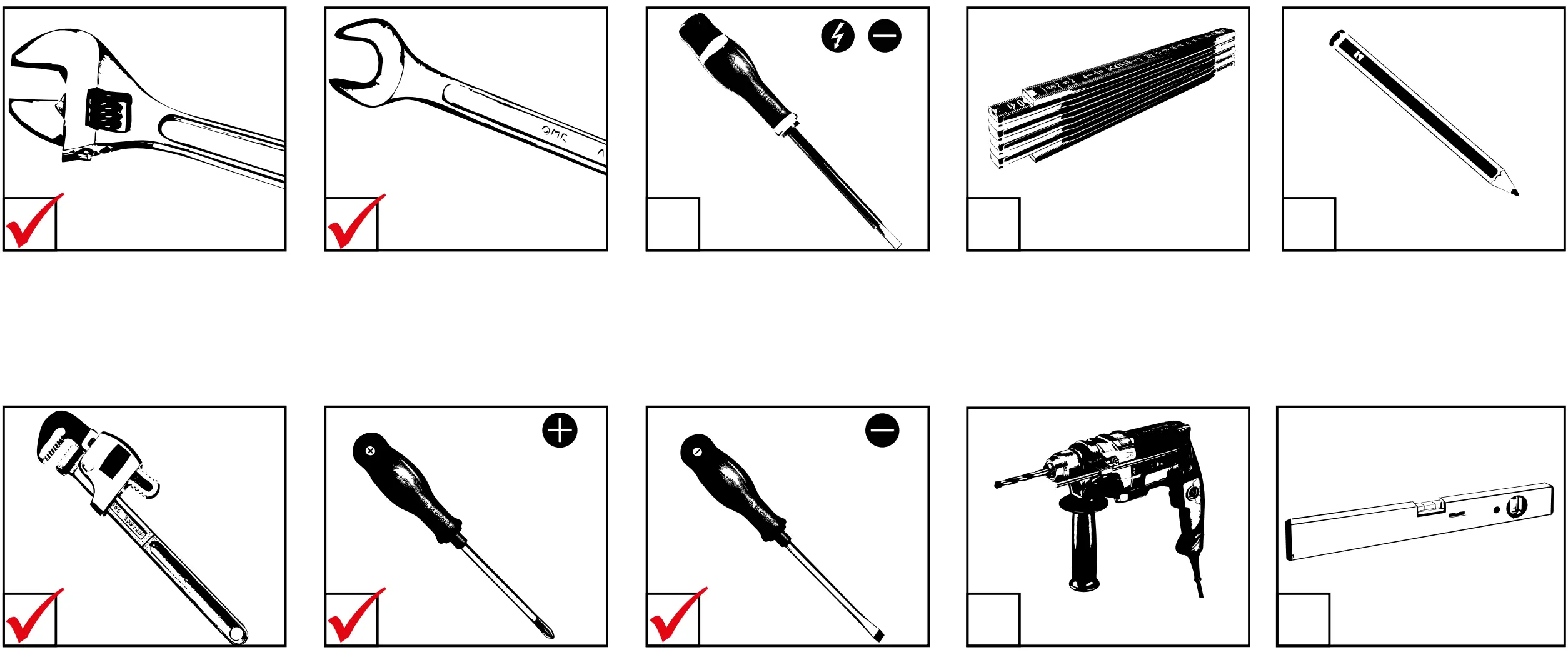
TOOLS
TANK INSTALLATION
Floor mounting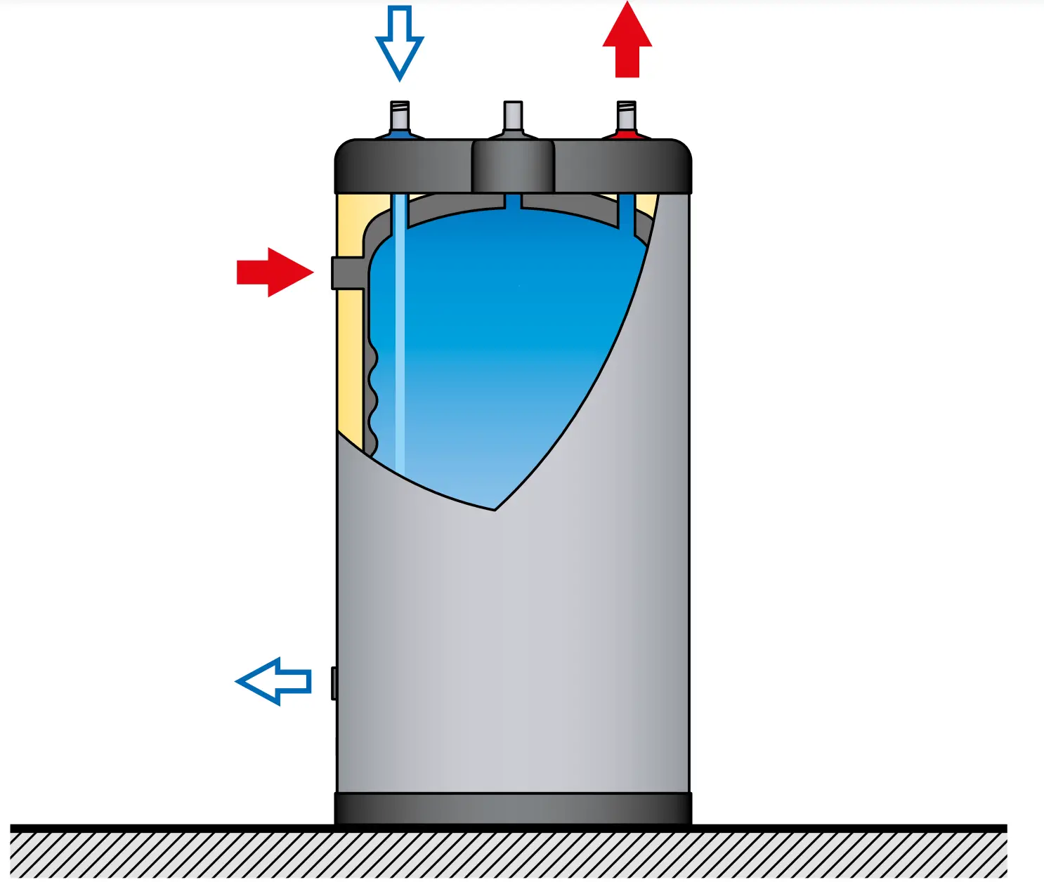
CONNECTION
![]() Essential instructions for the safety of persons and the environment
Essential instructions for the safety of persons and the environment
- Refer to the safety instructions for the installation. Failure to comply with these instructions can result in damages to the system, severe injuries or death.
- Hot water can burn! ACV recommends using a pre- set thermostatic mixing valve in order to provide hot water at a maximum of 60°C.
![]() Essential instructions for the correct operation of the system
Essential instructions for the correct operation of the system
- The filling circuit of the DHW tank must be equipped with a safety group, comprised at least of a stop valve, a check valve, a safety valve set at 7 bar, and possibly, an expansion vessel of the appropriate size. Make sure that the circuit between the tank and the safety valve is always open.
- The third DHW tank connection, if any, can be used for the auxiliary DHW loop.
If the connection is not used, replace the protective plug by a brass plug of the appropriate size.
![]() General remarks
General remarks
- In certain countries the domestic kits must be approved.
- The circuit illustrations are basic principle diagrams only
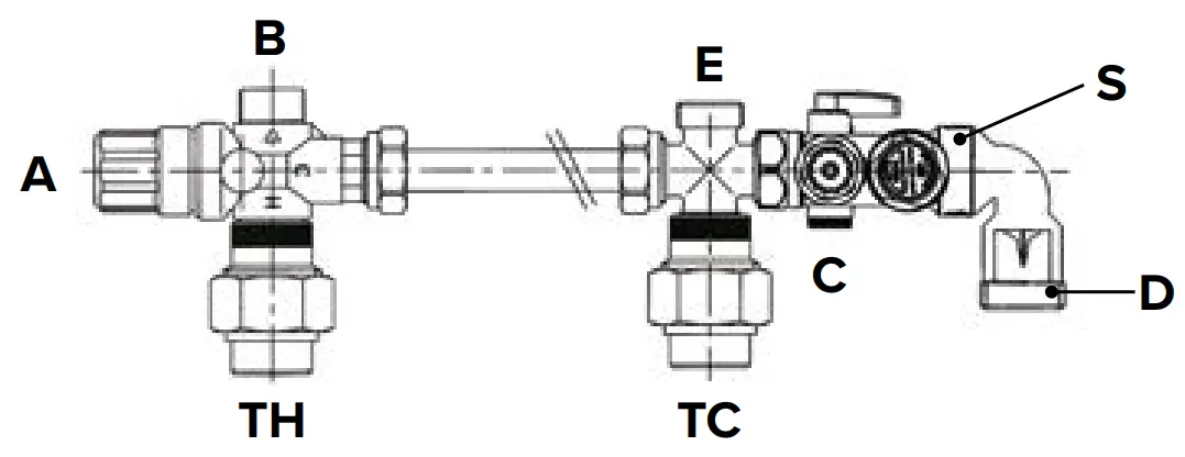
AVAILABLE KITS AND ACCESSORIES
Domestic hot water kit
- A. Thermostatic mixing valve
- B. Mixed water outlet
- C. Cold water inlet
- D. Drain connection
- E. Expansion vessel connection
- S. Safety unit
- TH. Outlet hot water tank
- TC. Inlet cold water tank
FLOOR MOUNTING
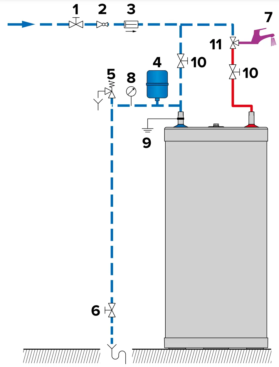
CONNECTION TO THE DHW CIRCUIT (Typical floor installation)
![]()
Key
- Filling valve
- Pressure reducing valve (set at 4.5 bar)
- Check valve
- Expansion vessel
- Safety valve (set at 7 bar)
- Drain valve
- Hot water outlet
- Pressure gauge
- Grounding
- Stop valve
- Thermostatic mixing valve
CONNECTION TO THE PRIMARY CIRCUIT (Typical floor installation)
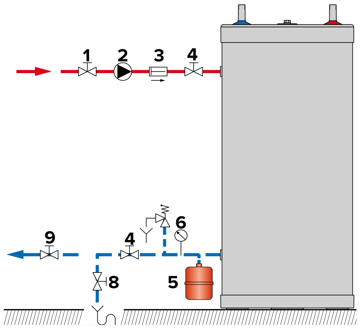
Key
- Primary circuit filling valve
- Charging pump
- Check valve
- Primary circuit stop valve
- Expansion vessel
- Pressure gauge
- Safety valve
- Drain valve
- Stop valve
Starting Up
SAFETY INSTRUCTIONS TO FILL THE TANK
![]() Essential instructions for the safety of persons and the environment
Essential instructions for the safety of persons and the environment
- The DHW tank must always be filled and pressurised before filling and pressurising the primary circuit.
- Do not use vehicle antifreeze. This can cause serious injury or death, or damage facilities.
- If antifreeze is needed in the primary circuit, it must comply with Public Hygiene Regulations and must be non-toxic. A food-grade Propylene Glycol is recommended. It must be diluted according to the ratio recommended in the local regulations.
- Consult the manufacturer to determine the compatibility of the antifreeze with the tank’s construction materials.
![]() Essential instructions for the correct operation of the system
Essential instructions for the correct operation of the system
- Before bringing the tank into service, check the connections to avoid any risk of leaks during filling.
- Only use drinking water to check that the DHW tank is watertight. The on-site test pressure must not exceed a pressure surge of 8,6 bar.
- Using antifreeze in the primary circuit will lead to a reduction in the heating performance. The higher the concentration of antifreeze in the circuit, the lower the performance.
FILLING
![]() Essential instruction for the correct operation of the system
Essential instruction for the correct operation of the system
- The DHW tank must always be filled and pressurised before filling and pressurising the primary circuit.
FILLING THE DHW TANK
![]()
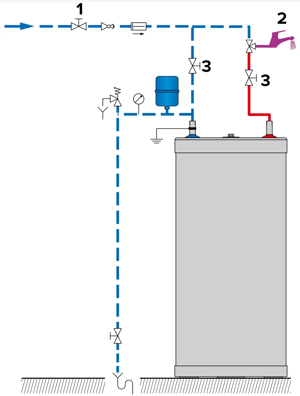
Figure 1
![]() General remark
General remark
- Connect the safety valve outlet to the sewer.
- To fill the tank, open a hot water tap (2) located at the highest point of the system. It enables to bleed the air from the system.
- Open the filling valve (1) and the stop valves (3) to fill the DHW tank.
- Close the hot water tap (2), after the water flow has stabilised and the air has been completely evacuated.
- Check all the connections of the system for leaks.
FILLING THE PRIMARY CIRCUIT
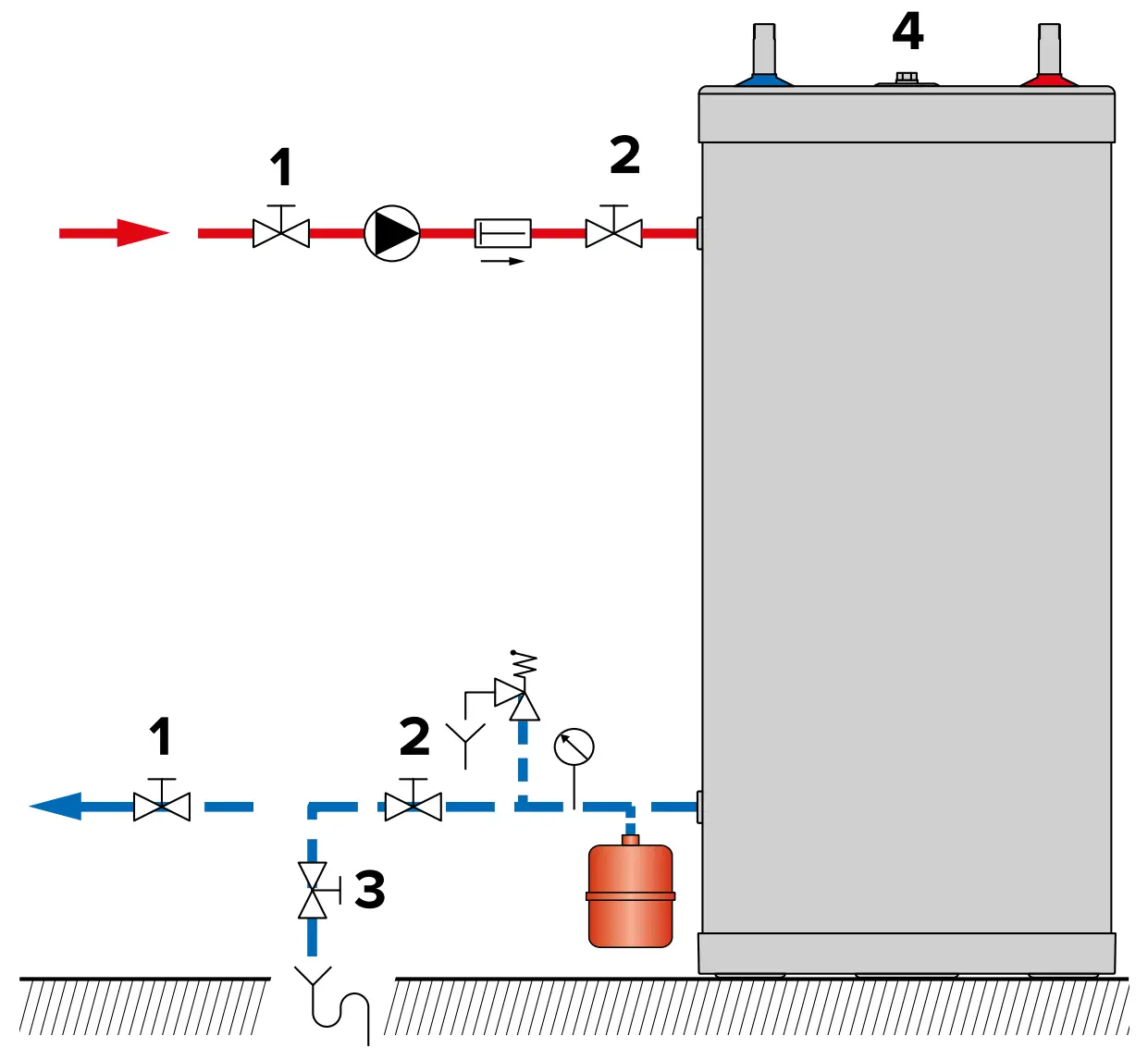
Figure 2
![]() General remark
General remark
If the tank is used within a heating system, refer to the heating boiler manual.
- Check that the drain valve (3) of your primary circuit is tightly closed.
- Open the stop valves (1) and (2) of the primary circuit connected to the heating boiler.
- Open the air bleed valve (4) located on the top of the hot water tank.
- When the air is eliminated, close the air bleed valve (4). Make sure the air bleed valve is tight.
CHECKS BEFORE STARTING UP
- Check that the safety valves (DHW and primary) are correctly installed and that the outlets are connected to the sewer.
- Check that the DHW tank and the primary circuit are filled with water.
- Check that the air has been correctly bled from both circuits.
- Check that the tank’s upper air bleed valve is tight.
- Check that the water side and heat source side pipes are correctly connected and not leaking.
STARTING UP PROCEDURE
As the Smart Green tank is used within a heating system:
![]() To put the heating system into service, refer to the heating boiler manual.
To put the heating system into service, refer to the heating boiler manual.
- Adjust the required temperature using the control thermostat.
Maintenance
PERIODIC CHECKS BY THE USER
- Check the pressure of the primary circuit pressure gauge: it should be between 0.5 and 1.5 bar.
- Visually inspect, on a regular basis, the valves, connections and accessories in order to detect any leaks or malfunction.
- Periodically check the air bleed valve located on the tank top to ensure that it is not leaking.
- Check that the DHW water circuit safety valves are in good operating condition.
- In the event of a problem, please contact an engineer or your installer.
ANNUAL MAINTENANCE
![]() Essential instructions for the correct operation of the appliance
Essential instructions for the correct operation of the appliance
- The discharge pipe of the safety unit must be open to the outside. If the safety unit drips periodically, it may be due to an expansion problem or clogging of the valve.
- For internal inspections, the hand hole can be used. If there is none, use one of the water connections to insert the appropriate inspection equipment. If necessary, drain the tank before inspection.
The annual maintenance service, performed by an engineer, must include:
- A check of the air bleed valve: the bleeding of air can lead to the need for adding water to the system.
- A check of the primary and DHW circuit pressure gauges.
- The manual activation of the storage water circuit safety valve once a year. This operation will lead to a discharge of hot water.
- A check of the correct operation of valves, taps, control units and accessories that are possibly installed [refer to the manufacturer’s instructions if necessary].
DRAINING
![]() Essential instruction for the safety of persons and the environment
Essential instruction for the safety of persons and the environment
- The water coming out of the drain valve is very hot and can cause very severe burns. Make sure the area around the hot water flow is clear of people.
![]() Essential instruction for the electrical safety
Essential instruction for the electrical safety
- Shut down the external electrical supply of the appliance before draining.
![]() Essential instructions for the correct operation of the system
Essential instructions for the correct operation of the system
- Drain the tank if it is not used in winter and is at risk from exposure to ice.
If the primary circuit water contains antifreeze, only the DHW tank must be drained. If the heating circuit does not contain antifreeze, the heating circuit and domestic water must be drained. - Before draining the DHW, isolate the tank and lower the pressure of the heating circuit to 1 bar, in order to prevent the DHW tank from being crushed.
DRAINING THE PRIMARY CIRCUIT
Figure 3
To drain the primary circuit of the hot water heater:
1. Stop the charging pump.
2. Isolate the primary circuit by closing the stop valves (1).
3. Connect the drain valve (2) to the sewer using a flexible hose.
4. Open the drain valve (2) and drain the water from the primary circuit to the drain.
5. Open the tank’s air bleed valve (3) to accelerate drainage.
6. Close the drain valve (2) and air bleed valve (3) after draining the tank.
DRAINING THE DHW TANK
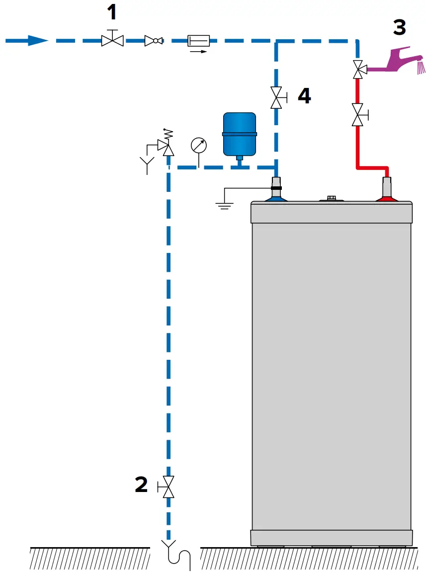
Figure 4
To drain the hot water heater’s DHW tank:
- Open fully the hot water tap (3) for at least 60 minutes to make sure the DHW tank has cooled down sufficiently.
- Close the filling valve (1) and the stop valve (4).
- Connect the drain valve (2) to the sewer using a flexible hose.
- Open the drain valve (2) and drain the water from the DHW tank to the sewer.
- To accelerate the tank’s drainage, open a hot water tap located higher than the tank connection in the DHW circuit.
- Close the drain valve (2) and the hot water tap (3) after having drained the DHW tank.
BRINGING BACK INTO SERVICE AFTER MAINTENANCE
Refer to “Starting Up”, page 17


![Midea Smart Ac [cw058iu-awifi] User Manual](https://static-data1.manualsee.com/1/img/294/17740/2020/12/Midea-Smart-AC-CW058IU-AWIFI.png "Midea Smart Ac [cw058iu-awifi] User Manual")


