![]() 27016 Blackbox 610R Competition
27016 Blackbox 610R Competition
Owner’s Manual
INTRODUCTION
Reedy’s Blackbox 610R Competition ESC utilizes the latest electronics technology along with the design and engineering experience responsible for 30 IFMAR World Championship titles.
Track tested and competition proven, Reedy’s Blackbox 610R is a versatile and powerful ESC specifically designed for those seeking maximum performance without compromise. Excellent throttle and brake feel, a wide range of adjustability, and robust hardware make the Blackbox 610R suitable for a wide variety of racing applications. Please read the following instructions before Installing and operating your ESC.
Features
- CNC machined black aluminum case with integrated heat sink
- Fully adjustable brake, throttle, power, and safety functions*
- Blinky mode with ROAR approved software
- Precision throttle and brake control
- Ultra-low resistance FET board
- 32-bit microcontroller unit (MCU)
- On-board power button
- Solder tabs w/13-gauge power wires
- Pro external capacitor board
- RPM and ESC temp data logging*
- Firmware updateable*
*Requires Blackbox Programmer2 #27027
Specifications
| Blackbox 610R | |
| Voltage input | 2S LiPo |
| On resistance (Ω) | 0.00043 |
| Continuous current (A) | 160 |
| Dimensions (mm) | 38.5 x 36.9 x 19.5 |
| Weight w/o wires (g) | 45 |
| Motor limit | 4.5T |
| BEC | 6.0-7.4V/5A |
| Cooling fan | optional |
SAFETY PRECAUTIONS
This product is a sophisticated hobby product and not a toy. It must be operated with caution and common sense and requires some basic mechanical ability. Failure to operate this product in a safe and responsible manner could result in injury or damage to the product or property. This product is not intended to be used by children without direct adult supervision. It is essential to read and follow all instructions and warnings found in this manual prior to installation, set up, and use, for the product to operate properly and to avoid damage or injury.
WARNINGS
- Never expose your ESC to water
- Never operate your ESC/motor under no load at high RPM
- Never apply reverse voltage
- Always unplug the battery from the ESC when not In use or while in storage
- Never let children use this product without the strict supervision of an adult
- Never leave the ESC unattended while powered ON
- Always use caution when handling your ESC as it may become extremely hot during use
- Always disconnect the battery and stop using the ESC if it begins to act abnormally
- Always power ON your transmitter before the ESC and power OFF the ESC before the transmitter
IMPORTANT
ESCs that display evidence of contact with moisture, reverse voltage, or internal/external modifications to wiring are not covered under warranty.
INSTALLATION
- Determine the most convenient location to mount your ESC taking into consideration easy access to the battery connectors and Power button
- Determine the ideal sensor wire length and plug it into the ESC’s sensor port
- Cut the battery and motor wires to the desired length
- Solder the appropriate battery connector(s) to the battery leads
- Mount your ESC/capacitor unit securely using high quality double-sided tape
- Plug the RX wire into the receiver (refer to radio manufacturer’s manual)
- Solder the three ESC motor leads labeled A-B-C to the corresponding motor tabs labeled A-B-C
POWERING THE ESC ON/OFF
- To turn the ESC ON, press the Power button.
- To turn the ESC OFF, press and hold (.1 sec) the Power button or unplug the battery.
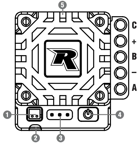
- Fan port
- RX wire
- Program port
- Power button. green/red LED
- Sensor Pod
ESC/RADIO CALIBRATION
- Power ON the transmitter and adjust the throttle/brake endpoints to 100% and the throttle trim to neutral.
- Plug the ESC into a charged battery and place your vehicle on a stand with the wheels off the ground.
- While the transmitter is at neutral and the ESC off, press and hold the Power button until the green LED illuminates and remains solid. The ESC will emit a continuing beep. Release the Power button.
- While the transmitter is in the neutral position, press the Power button. The green LED will blink until the red LED illuminates and remains solid. The ESC will beep once indicating that the neutral point has been saved.
- Move the transmitter to the full throttle position and press the Power button. The red LED will blink until both the red and green LEDs illuminate and remain solid. The ESC will beep twice indicating that the full throttle position has been saved.
- Move the transmitter to the full brake position and press the Power button. The red and green LEDs will blink and then go off. The ESC will beep three times indicating that the full brake position has been saved.
- Return the transmitter to neutral and the ESC will beep to indicate that the calibration process is successful. The green LED will either blink (zero-timing default setting) or remain solid (depending on activation of timing settings when using the Programmer) to signify that it is in the neutral position. If the ESC is in Forward/Reverse/Brake mode, the red LED will also illuminate and remain solid while at the neutral position.
- The ESC calibration is complete, and the ESC is ready to use.
IMPORTANT ESC/Radio calibration must be completed with new ESCs, w en c anging transmitters, after firmware updates, and after repair service.
PARTS LISTINGS
27016 Blackbox 610R Competition ESC
27017 Blackbox 610R Competition ESC w/Programmer2
27027 Blackbox Programmer2
27028 Blackbox 30x30x7mm Fan w/screws
27029 Blackbox Pro Modified Capacitor Unit
27030 Blackbox ESC Programmer2 Connection Wire
27031 Blackbox 30x30x1Omm Fan w/screws
| DEFAULT SETTINGS | ||||
| Tuning Mode | Standard | Expert | ||
| Brake | 1A | Drag Brake | 4% | 10% |
| 1B | Brake Strgth | 90% | 80% | |
| 1C | Init Brake | =Drag Brake | =Drag Brake | |
| 1D | Brake Freq | 4KHz | 4KHz | |
| 1E | Brake Punch | Level 5 | Level 5 | |
| 1F | Brake Mode | Traditional | Traditional | |
| Throttle | 3A | Punch Ctrl | Level 25 | Level 4 |
| 3B | Init Throttle | 2% | 0% | |
| 3C | Drive Freq | 8KHz | 12KHz | |
| 3D | Dead Band | 6% | 6% | |
| 3E | Current Limit | 100% | 100% | |
| Motor Power | 4A | BT Soft Pwr | NA | 10° |
| 4B | BT Soft Rng | NA | 25% | |
| 4C | Coast Value | NA | 0% | |
| 4D | Boost Timing | NA | 0° | |
| 4E | Boost Tim Act | NA | RPM | |
| 4F | Boost ST RPM | NA | 15000 | |
| 4G | Boost End RPM | NA | 40000 | |
| 4H | Turbo Timing | NA | 5° | |
| 4J | Turbo Delay | NA | 0.05° | |
| 4K | Slew Rate | NA | 3°/0.1s | |
| 4L | Release Rate | NA | 3°/0.1s | |
| 5A | Timing Level | Level 0 | NA | |
| Misc. Control | 6A | Run Mode | For/Brake | For/Brake |
| 6B | Reverse Power | 25% | 25% | |
| 6C | Batt Cutoff | 3.4V/cell | 3.4V/cell | |
| 6D | ESC Temp Cut | 257F/125C | 257F/125C | |
| 6E | Mot Rotation | Normal | Normal | |
| 6F | BEC Voltage | 6.0V | 6.0V | |
| 6G | Reset Default | NA | NA | |
NOTE
A cooling Ian is recommended when the ESC is used in modified Touring Car and 4wd Buggy claSses, when utilizing ESC timing, and when used in high temperature environments. 
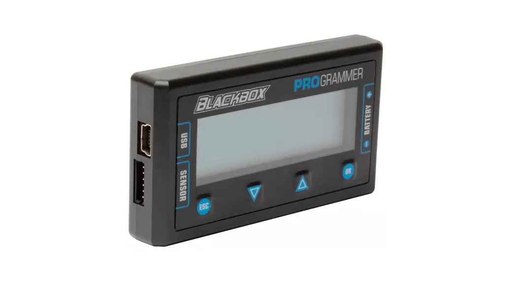
Your Blackbox 610R ESC includes two modes that can be modified and saved independently from one another. Standard mode offers a wide variety of tuning options while Expert mode takes it one step further and opens additional options for more experienced racers and/or racing classes that can take advantage of these advanced settings. To switch between Standard and Expert modes, or to make and save changes to the settings in either mode, you must use Blackbox Programmer2 427027.
CHANGE SETTINGS
- Plug the Programmer2 extension wire into the programmer port on the ESC.
- Power ON the ESC.
- Press OK after the Blackbox Programmer, PB Firmware Version, and ESC Firmware Version splash screens.
- Select Standard or Expert tuning mode using the up/down arrows to select the mode and OK to make the selection.
- Use the ESC and OK buttons to scroll to the desired setting option to be changed.
- Use the up/down arrow buttons to select the value for that setting.
- When a custom value is available, press and hold OK until the value flashes, then use the arrow buttons to change the value. When you are satisfied with your selection, press and hold the OK button for approximately one second until the value stops flashing.
- Changes are saved immediately. Once all changes are completed, unplug the Programmer2 extension wire from the ESC.
- Power OFF the ESC. The new settings will take effect the next time the ESC is powered ON.
NOTE: Asterisks indicate the ESC’s default settings.
TUNING MODE
Standard (Standard) – Disables complex settings and simplifies Timing Level options by offering pre-selected options as well as zero-timing blinky mode. This selection is recommended for Spec class racers and most off-road classes. Expert (Expert) – Allows users to access and fine tune advanced timing settings. This selection is recommended for modified on-road, carpet off-road, and oval classes.
NOTE: Tuning Mode can only be selected when the Programmer2 is initially
connected to the ESC.
BRAKE
Drag Brake (1A Drag Brake) – Drag Brake is a percentage of the Brake Strength and provides automatic braking when the throttle trigger is returned to the neutral position. The Drag Brake value requires adjustment when changes to the Brake Frequency and Brake Strength are made.
Brake Strength (1B Brake Strgth) – Changes the maximum brake strength of the ESC which in turn affects the feel of the Drag Brake and Initial Brake.
Initial Brake (1C ing Brake) – Determines the percentage of brake the ESC applies the moment the trigger is moved If0111 the neutral range to the brake range. A setting of .Drag Brake is recommended for most applications. A setting greater than the selected drag brake setting will provide a more aggressive initial brake feel. The Initial Brake setting should never be lower than the Drag Brake selling.
Brake Frequency (10 Brake Freq) – A lower frequency will provide a more aggressive feel while a higher frequency will provide a smoother, more precise braking feel but may result in higher ESC temperatures.
Brake Punch OF Brake Punch) – Use to adjust the ESC’s response to brake input. Higher values provide faster response while lower values slow response and produce a smoother braking effect.
Brake Mode (1E Brake Mode) – Linear mode weakens brake action but provides excellent feel and control. Traditional mode provides the same braking action as the 510R and other Reedy Blackbox ESCs (recommended for most applications). Hybrid mode automatically switches from Traditional mode to Linear mode as vehicle speed decreases to help prevent loss of traction during heavy braking.
THROTTLE
Punch Control (3A Punch Ctrl) – By reducing the Throttle Punch setting, you will experience slower throttle response which may be advantageous in low traction conditions.
Initial Throttle (38 Mit Throttle) – Determines the percentage of throttle the ESC applies the moment the trigger is moved from the neutral range to the throttle range. A setting of 0% is typical and enables a smooth transition from a standing start. Higher values can be advantageous to spec racers who want instant power from neutral. For example, a setting of 15% means that the moment the throttle trigger is moved, the ESC immediately delivers 15% throttle.
Drive Frequency (3C Drive Freq) – A lower frequency will provide a more aggressive throttle feel. A higher frequency will provide a smoother, more precise throttle feel but may also result in higher ESC temperatures.
Dead Band (3D Deadband) – Adjusts the percentage of trigger movement available before the throttle/brake initially engages.
Current Limiter (3E Current Limit) – Adjusts the maximum amount of current allowed upon motor start up. Limiting current can reduce wheel spin, lower temperatures. and increase run time. A value of 100% means the limiter is disabled while reducing the value provides increased limiting.
MOTOR POWER – EXPERT
The Blackbox 610R ESC features advanced settings that allow individual adjustment of acceleration (Boost) and top speed (Turbo) timing. These are particularly useful on large tracks in applications such as 1/10 Modified Touring Car and Spec classes where ESC timing is permitted. Each setting can be used individually or together to achieve maximum speed. To operate in zero-timing blinky mode, the Boost Timing, Turbo Timing, BT Soft Power and BT Soft Power Range values must all be set at 0. BT Soft Power (4A BT Soft Pwr) – Useful for taming the bottom end power when using high-powered modified motors. A higher value reduces power for a less aggressive bottom end without sacrificing power at the mid-range and top end.
BT Soft Power Range (4B BT Soft Rng) – Sets the range in which the BT Soft Power setting is activated. A 10% setting, for example, means that BT Soft Power is activated in the first 10% of the throttle range.
Coast Value (4C Coast Value) – Reduces the speed at which the motor RPM is reduced from high-speed to neutral. This can help reduce unsettling of the chassis by altering weight transfer. A higher value Increases the effect while a 0% setting deactivates it.
Boost Timing (4D Boost Timing) – Sets the maximum advanced timing when the motor reaches the Boost End RPM. This value must be set at 0° for zero-timing stock classes.
Boost Timing Activation (4E Boost Tim Act) – When RPM is selected, the activation start and end RPM are manually chosen. When Auto is selected, the activation start point is automatically selected based on motor RPM and throttle position. Boost Start RPM (4F Boost ST RPM) – Sets the RPM at which Boost Timing begins. Boost End RPM (40 Boost End RPM) – Sets the RPM at which Boost Timing ends.
Turbo liming (4H Turbo Timing) – The maximum timing added during Turbo Timing activation. Turbo Timing is activated at the full throttle position. This value must be set at 0° for zero-timing stock classes.
Turbo Delay (4J Turbo Delay) – Once maximum throttle is detected, the ESC delays Turbo Timing activation using this setting.
Slew Rate (4K Slew Rate) – Sets the rate at which the ESC adds Turbo Timing. A higher value adds timing faster while a lower value adds timing more slowly. Selecting Instant adds timing immediately.
Release Rate (4L Release Rate) – Sets the rate at which the ESC reduces Turbo liming. A higher value reduces timing faster while a lower value reduces timing more slowly. Selecting Instant reduces timing immediately.
| SETTINGS MENU | ||||||
| Tuning Mode | Standard, Expert | |||||
|
Brake | 1A | Drag Brake | 0% – 16%, (2% increments), Custom 0% – 100% (1% Increments) | |||
| 1B | Brake Strgth | 75% – 150% (5% increments) | ||||
| 1C | Init Brake | = Drag Brake, 0% – 16% (2% increments), Custom 0% – 50% (1% increments) | ||||
| 1D | Brake Freq | 500Hz, 1KHz, 1.5KHz, 2KHz, 2.5KHz, 3KHz, 4KHz, 6KHz, 8KHz, 12KHz, 16KHz | ||||
| 1E | Brake Punch | Level 1-20 | ||||
| 1F | Brake Mode | Linear, Traditional, Hybrid | ||||
|
Throttle | 3A | Punch Ctrl | Level 1-30 | |||
| 3B | Init Throttle | 0% – 40% (1% increments) | ||||
| 3C | Drive Freq | 1KHz, 2KHz, 3KHz, 4KHz, 6KHz, 8KHz, 12KHz, 16KHz, 24KHz, 32KHZ | ||||
| 3D | Deadband | 2% – 12% (1% increments) | ||||
| 3E | Current Limit | 50% – 100% (1% increments) | ||||
| Motor Power | Standard | Expert | ||||
| 5A | Timing Level | Level 0 – 0° Blinky | 4A | BT Soft Pwr | 0° – 20° (1° increments) | |
| Level 1 – 3° | 4B | BT Soft Rng | 0% – 75% (5% increments) | |||
| Level 2 – 6° | 4C | Coast Value | 0% – 20% (1% increments) | |||
| Level 3 – 9° | 4D | Boost Timing | 0° Blinky – 64° (1° increments) | |||
| Level 4 – 12° | 4E | Boost Tim Act | Auto, RPM | |||
| Level 5 – 15° | 4F | Boost ST RPM | 500 – 35000 (500 increments) | |||
| Level 6 – 18° | 4G | Boost End RPM | 3000 – 60000 (500 increments) | |||
| Level 7 – 21° | 4H | Turbo Timing | 0° Blinky – 64° (1° increments) | |||
| Level 8 – 24° | 4J | Turbo Delay | Off, 0.05s – 1.0s (0.05s increments), Instant | |||
| Level 9 – 27° | 4K | Slew Rate | 3°/0.1s – 30°/0.1s (1° increments), Instant | |||
| Level 10 – 30° | 4L | Release Rate | 3°/0.1s – 30°/0.1s (1° increments), Instant | |||
|
Misc. Control | 6A | Run Mode | For/Brake, For/Brake/Rev | |||
| 6B | Reverse Power | 25%, 50%, 75%, 100% | ||||
| 6C | Batt Cutoff | None, 3.2V/cell, 3.4V/cell | ||||
| 6D | ESC Temp Cut | Off, 221F/105C, 257F/125C | ||||
| 6E | Mot Rotation | Normal/Reverse | ||||
| 6F | BEC Voltage | 6.0V – 7.4V (0.1V increments) | ||||
| 6G | Reset Default | No/Yes | ||||
| Telemetry | 7A | RPM Memory | (no selection required) | |||
| 7B | Temp Memory | (no selection required) | ||||
MOTOR POWER – STANDARD
For those that need additional power but who prefer not to deal with complicated timing settings, the detailed settings have already been worked out for you.
Timing Level (5A Timing Level) – When racing Spec classes and classes that require the use zero-timing blinky mode, select Level 0. Level 1-10 activates Turbo Timing to increase power output and top speed which is useful when racing off-road vehicles on larger and/or high-grip tracks and in the Modified TC classes.
MISCELLANEOUS CONTROL
Run Mode (6A Run Mode) – Select the appropriate mode depending on if the ESC is used for racing or for practice.
Reverse Power (6B Reverse Power) – Adjusts reverse power when For/ Brake/Rev has been selected as the Run Mode.
Low Voltage Battery Cutoff (6C Batt Cutoff) – Select the cell voltage at which the ESC will power off to prevent over-discharge of the battery. Disabling the cutoff is an option but not recommended for most racing applications.
ESC Temperature Cutoff (6D ESC Temp Cut) – The temperature at which the ESC will cut power to the motor to prevent permanent damage to the ESC. Disabling the cutoff is an option but not recommended and doing so will void the warranty.
Motor Rotation (6E Mot Rotation) – Reverses the motor’s direction of rotation it required by a vehicle’s design.
BEC Voltage (6F BEC Voltage) – Values between 6.0V or 7.4V can be chosen to match the input voltage requirements of the selected servo or to fine tune the servo’s speed for the desired feel. Unless FIV servos are being used, 6.0V is recommended.
Reset Default Settings (6G Reset Default) – Restores the factory default settings.
TELEMETRY
Motor RPM Memory (7A RPM Memory) – Recall the maximum motor RPM from your most recent run. The data is stored in memory until the next time the ESC is powered on and operated.
ESC Temperature Memory (7B Temp Memory) – Recall the maximum ESC temperature from your most recent run. The data is stored in memory until the next time the ESC is powered on and operated. Setup sheets obtained from Reedy team drivers can be found at www.ReedyPower.com. These can be extremely helpful in determining good starting setups for your application. Blank editable setup sheets are also available which can be filled out and printed or saved for future reference.
FIRMWARE UPDATES
Firmware for both the Blackbox 610R ESC and Programmer2 can be updated after downloading the appropriate firmware and Blackbox Link installation program. These, along with installation and operating instructions, can be found at www.ReedyPower.com.
WARRANTY
Your Reedy Blackbox ESC is warranted to the original purchaser for 120 days from the date of purchase, verified by the sales receipt, against defects in material and workmanship. Product that has been mishandled, abused, used incorrectly, used for an application other than intended, or damaged by the user are not covered under warranty. Associated Electrics Inc. is not liable for any loss or damage, whether direct or indirect, incidental or consequential, or from any special situation, arising from the use, misuse, or abuse of this product.
TROUBLESHOOTING
| Problem | Cause | Solution |
| ESC overheats | Motor over-geared | Change final drive ratio (FDR) |
| No ESC fan or damaged ESC fan | Install fan/new fan | |
| ESC Temp Cut set too low | Increase ESC Temp Cut value | |
| Lack of air flow | Reposition ESC | |
| Motor overheats | Mechanical timing too high | Reduce motor timing |
| Insufficient motor cooling | Add cooling fan and/or heatsink | |
| ESC timing settings too high | Reduce timing settings | |
| Weak rotor | Install new rotor | |
| Poor speed/ performance | Insufficient final drive ratio (FDR) | Change final drive ratio (FDR) |
| Transmitter settings changed | Verify correct full throttle setting | |
| External capacitor unit damaged | Install new capacitor unit | |
| Incorrect ESC settings | Verify correct settings | |
| Motor damaged or defective | Inspect and repair necessary components | |
| Damaged ESC | Return ESC for repair | |
| Motor stutters under acceleration | Damaged sensor wire | Replace sensor wire |
| Damaged motor sensor board | Replace sensor board | |
| External capacitor unit damaged | Install new capacitor unit | |
| Damaged ESC | Return ESC for repair | |
| No/reduced motor power, but servo functions | ESC plugged into RX incorrectly | Verify RX wire is plugged into Ch. 2 |
| ESC Temp or Batt Cutoff engaged | Wait for ESC to cool or re-charge battery | |
| Motor damaged or defective | Repair or install new motor | |
| Motor sensor wire missing or damaged | Install or replace motor sensor wire | |
| Damaged ESC | Return ESC for repair | |
| No motor and servo power | ESC RX wire plugged in backwards | Plug the RX wire in correctly |
| Poor battery connection/defective battery | Improve connection or replace battery | |
| No radio signal | Check/re-bind TX/RX | |
| Damaged ESC | Return ESC for repair | |
| ESC works intermittently | Batt Cutoff voltage set too low | Reduce battery cutoff voltage |
| Dead or damaged battery | Charge or replace battery | |
| Bad battery connection | Improve connection or replace battery | |
| Damaged motor | Repair or replace motor | |
| Damaged ESC | Return ESC for repair |
OPERATION AND WARNINGS
| Operation | ESC Signal | ||
| Red | Green | ||
| 0° Blinky | Timing | ||
| Neutral throttle position F/B Mode | blink | solid | |
| Neutral throttle position F/B/R Mode | solid | blink | solid |
| Full throttle position | solid | solid | |
| Full brake position | solid | ||
All LEDs should be off at any throttle/brake position other that neutral, full brake, or full throttle.
| Warning | ESC Signal | Motor Power | ||
| Red | Green | |||
| 0° Blinky | Timing | |||
| LVC engaged | blink | reduced* | ||
| ESC temp cutoff | solid | reduced* | ||
| No radio signal | blink alternately | |||
| Sensor wire removed/failure | blink | blink | ||
*Full operation resumes when the ESC is powered OFF and ON, and the problem that signaled the shutdown has been resolved.![]() Associated Electrics, Inc. declares that this product complies CE with the essential requirements and other relevant provisions of the European directive 2014/30/EU.
Associated Electrics, Inc. declares that this product complies CE with the essential requirements and other relevant provisions of the European directive 2014/30/EU.![]() The crossed-out wheeled bin means that within the European Union the product must be taken to separate collection at the product’s end of life. Do not dispose of these products as unsorted municipal waste.
The crossed-out wheeled bin means that within the European Union the product must be taken to separate collection at the product’s end of life. Do not dispose of these products as unsorted municipal waste.
![]() www.ReedyPower.com
www.ReedyPower.com
21062 Bake Parkway, Lake Forest, CA 92630 USA


