
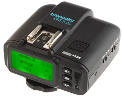
![]() RFS 2.2
RFS 2.2
Canon Fujifilm Nikon Sony
Instruction Manual
Operating instructions
SCOPE OF DELIVERY

| 1 Case 2 Micro-USB In 3 Sync In / Out 4 Status indicator | 5 “test” key 6 Modelling light (on / off) 7 Main switch (on / off) 8 “ST” key (studio channel setting) |
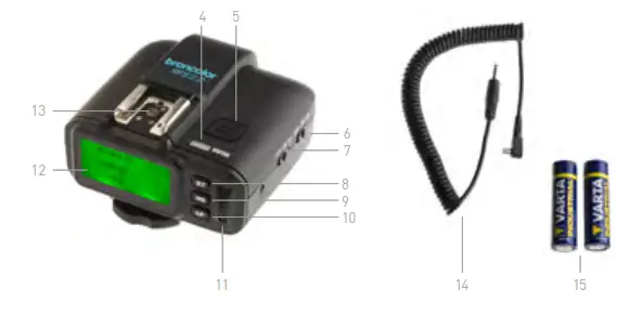
| 9 “HS” key (HS on / off and setting) 10 “LP” key (lamp channel setting) 11Scrolling wheel (for various settings) | 12 Display 13 Top hot shoe for accessories 14 Synch cable to camera 15 2 batteries, AA |
BRONCOLOR RADIO FREQUENCY SYSTEM 2.2
Before use
We are very pleased you have chosen one of our RFS 2.2 transceiver units. If used properly, it will render you many years of good service. Please read the information contained in these operating instructions carefully. They contain important details on the use, safety, and maintenance of the device. Keep these operating instructions in a safe place and pass them on to further users if necessary
With the radio system brown color RFS 2.2 you can trigger and operate by remote control brown color units, which are equipped with an integrated RFS 2 interface. RFS 2.2 is available in four versions, for Canon, Fujifilm, Nikon, and Sony, always optimized for its operation. The use of other camera systems is not recommended.
With the additional HS function, HS-compatible brown color flash units, in combination with a suitable camera, can be set to use the shortest possible shutter speeds (down to 1/8000 s).
The transceiver can be operated in either of two modes. As supplied, the transceiver operates as a transmitter.
RFS 2.2 TRANSCEIVER AS TRANSMITTER
The RFS 2.2 transceiver operates as a remote control or radio flash trigger for one or more broncolor power packs or monolights equipped with an RFS 2 interface. Power packs or monolights not equipped with an RFS 2 interface can be operated by connecting an RFS 2.2 Transceiver (as receiver) – see Chapter 10.
All devices, whether with a built-in RFS 2 or an external RFS 2.2 receiver are compatible. If several RFS 2 units are to communicate with each other, they must be set to the same studio address. RFS 2 units with the same studio address can be remote-controlled simultaneously. By using different studio addresses, several groups of devices can be reliably operated independently of each other. Flash synchronization takes place either via the hot shoe or using the camera’s sync contact. The operating distance is up to 50 m in the open air, or up to 30 m in a building. The transmitter is fitted with two AA batteries.![]() Attention! Although this radio system allows up to 99 studio addresses, the number of channels that is effectively available is restricted by the RFS 2 flash unit to be controlled.
Attention! Although this radio system allows up to 99 studio addresses, the number of channels that is effectively available is restricted by the RFS 2 flash unit to be controlled.
For further instructions, please see the operating instructions for the flash unit concerned.
OPERATION
Keys
The unit has three menu keys, a scrolling wheel, a “test” key and two slide switches, one for modeling light and one to switch the unit on and off.
> Duration of key presses
A short press of a key is one that takes less than one second, a long press is longer than one second.
Overview of key functions
| Key | Operation | Function executed | Comments |
| test | Press key briefly | Triggers a test flash | |
| test | A long press of key and switch unit on | Unit settings (see Chapter 7) | |
| ST | Press key briefly | Opens the studio menu and confirms the setting Studio Energy | Turn the scrolling wheel to set the studio energy |
| ST | Press key for a longer | Opens the studio menu and confirms the setting Studio | Turn the scrolling wheel to set the studio channel |
| Key Operation | Function executed | Comments |
| HS Press key briefly | Opens the HS menu and confirms the setting | Turn the scrolling wheel to switch the HS function on or off |
| HS Press key for longer | Opens the HS menu and confirms the setting HSMA (HS Manual Adjust) | Using the scrolling wheel the optimum flash the triggering point can be selected manually |
| LP Press key briefly | Opens the lamp menu and confirms the setting lamp energy | Turn the scrolling wheel to set the lamp energy |
| LP Press key briefly again | Changes the lamp channel | Turn the scrolling wheel to set the energy of the selected lamp |
| LP Press key for longer | Opens the lamp menu and confirms the setting Number of lamps | Turn the scrolling wheel to set the maximum number of lamps per studio |
| Key | Operation | Function executed | Comments |
| OFF | Slide | Switches the unit on and off | |
| OFF | Slide | Switches the modeling light on or off |
Automatic switch off
After 10 minutes, the unit switches automatically to energy-saving mode. Press any key to reactivate the unit.
SETTING STUDIO ADDRESSES
The transceiver must have the same studio address as the flash units used. First set the studio address you want to use on the flash units, and then synchronize the RFS 2.2 transmitter.
To set the studio address (studio channel), please proceed as follows:
- Press the “ST” key for longer to enter the studio channel menu.
- Set the studio address with the scrolling wheel as required (01 to 99).
- Save the setting with a short press on the “ST” key. The transceiver syn- chronicles with the flash units.
SETTING THE LAMP CHANNEL
With the RFS 2.2 transceiver, you can set the energy control per channel as you wish as well as adjust the number of lamps per studio.
To set the lamp address, please proceed as follows:
- Press the “LP” key briefly to enter the lamp setting menu.
- Set the lamp address with a short press on the “LP” key (several times if necessary).
To set the number of lamps used in your studio, please proceed as follows:
- Press the “LP” key for longer to enter the lamp setting menu.
- Set the number of lamps used in your studio with the scrolling wheel as required (01 to 40).
- Save the setting with a short press on the “LP” key.
ENERGY CONTROL
5.1 Preparation
A longer press on key “ST”: Turn the scrolling wheel as appropriate to change the studio channel up or down. Confirm the selection by a short press on key “ST”.
The RFS 2.2 transceiver allows you to change the energy setting of all RFS 2 flash units that are set to the same studio address (in the “ST” menu) and to change the output of individual lamp channels (in the “LP” menu). The output can be adjusted in 1/10 and full f-stop steps.
5.2 Menu “ST”
A short press on key “ST”: Turn the scrolling wheel upwards or downwards to increase or reduce the total energy of all units. This takes place in 1/10 f-stop steps. Confirm the selection by a short press on key “ST”.
5.3 Menu “LP”
A short press on key “LP”: Turn the scrolling wheel upwards or downwards to increase or reduce the energy of selected lamps. This takes place in 1/10 f-stop steps. Confirm the selection by a short press on key “LP”.
HS
6.1 Menu “HS”
The HS mode enables short exposure times (down to 1/8000 s) on the camera in combination with HS-compatible flash units.
Operating HS functions
- Mount a compatible RFS 2.2 transmitter on the camera
- Switch on the RFS 2 / HS-compatible broncolor flash unit
- Activate the RFS function on the flash unit
- Activate HS mode on the RFS 2.2. The flash unit switches automatically to HS mode
HS on / off
Press the “HS” key briefly: Turn the scrolling wheel up or down. HS mode switches on and off. Confirm the selection by a short press on key “HS”.
6.2 Menu “HSMA”
When HS is active, HSMA (HS Manual Adjust) improves the exposure to suit the camera model being used. The purpose of HSMA mode is to override the automatic HS flash trigger. The automatically calculated shutter release is canceled.
The delay of the flash trigger signal (HSMA) depends on the camera, and so is different from model to model. The transmitters are factory set to work correctly with most models of a given brand, however, if you should notice a black bar across the exposed image you should utilize the HSMA function to adjust the timing until the black bar is no longer visible in the exposed image.
longer press on key “HS” for HSMA (HS Manual Adjust): turn the scrolling wheel up or down. In this way, HSMA mode can be set individually. Confirm the selection by a short press on key “HS”.
UNIT SETTINGS (c.fn)
Operation
- Switch the RFS 2.2 unit off (slide the main switch to “off”)
- Press and hold the “test” key and simultaneously switch on the RFS 2.2 (slide main switch to “on”)
- Turn the scrolling wheel until you reach the desired function
- Mark the function with the “LP” key (set)
- Use the scrolling wheel to determine the property
- Press “LP” to confirm the selection (back)
| Display | Function | Selection | Description |
| c.fn-00 | transceiver | transmitter | Transmitter mode |
| receiver | Receiver mode | ||
| c.fn-01 | PC sync | output input | Select sync connection as output or input. When unit is in receiver mode, the PC port will be automatically set as output. When the unit is in transmitter mode, the PC port will be automatically set as input |
| Display | Function | Selection | Description |
| c.fn-02 | top hotshoe | single | On the top hot shoe, only the middle contact is active |
| multi | On the top hot shoe, all the contacts are active for operation with Speedlites | ||
| c.fn-03 | lcd | 0 – 5 | Change the brightness of the background illumination |
| c.fn-04 | firmware | V 1.2 (for example) | Information on firmware version |
| update | Start the update function with the “HS” key. Switch the unit off. Connect a micro-USB cable for PC / Mac between your computer and the RFS 2.2 unit. Follow the procedure shown on your PC / Ma |
RESET
> Reset of the unit
To reset the unit to its as-supplied condition, hold the “test” key down for longer than four seconds. The unit will then be reset.
COMPATIBILITY
| Transmitter | Flash unit | Comments |
| RFS 2.2 | RFS 2 | Full compatibility and HS mode are available |
| RFS 2.1 | RFS 2 | Triggering of individual lamps and modeling light control possible |
| RFS 2 | RFS 2 | On units with RFS 2, individual lamp control and modeling light control is not possible |
RFS 2.2 TRANSCEIVER AS RECEIVER
With broncolor power packs, moonlights, and lamps from other manufacturers, which are not equipped to receive RFS 2 data, the unit can be used as an external receiver.
The unit will not be automatically switched to receive when connected to a power pack or moonlight.
To switch from transmit mode to receive mode, or vice versa, please proceed as follows:
- Hold the “test” key pressed and simultaneously switch the unit on.
- Press the “LP” key and use the scrolling wheel to change to receive or transmit as appropriate.
- Press the “LP” key again to confirm the selection, and switch the unit off.
When it is switched on again, the switchover will have been completed. In receiver mode, the PC port will be automatically configured as an output. Connect the sync cable to the “out” socket of the RFS 2.2 transceiver and to the sync connection on the flash unit.
TECHNICAL DATA
| Studio address setting range | 1 – 99 |
| Lamp address setting range | 1 – 40 |
| Radiofrequency channels (automatically regulated) | 40 |
| Frequency | 2.4 GHz |
| Transmission time (transmitter to receiver) | 0.425 ms |
| Exposure speed, focal-plane shutter | in HS mode, down to 1/8000 s |
| Flash triggering by: | > Integral hot shoe, middle contact > Sync connection on the side |
| Operational distance in open air | up to 50 m / 164 ft |
| Operational distance in a building | up to 30 m / 98 ft |
| Antenna | integrated |
| Dimensions (l × w × h) | 72 × 75 × 52 mm / 2.8 × 3.0 × 2.0″ |
| Weight | 100 g / 0.2 lbs (incl. batteries) |
| Releases per second | 100 |
| Power supply | 2 AA batteries |
| Automatic switchover to energy-saving mode | after 10 minutes |
| Typical battery life | ca. 8 – 12 months, or 100’000 flashes |
| Sync voltage | 3 V |
In the event of problems and undefined communication malfunctions between RFS 2.2 devices, the cause may be strong frequency interference. In such cases, make sure the devices are not within the range of baby phones, video bridges, microwave ovens, cordless DECT telephones, Wlan routers, or Bluetooth devices, or use a different studio channel.
Subject to change in the interest of technical progress.
NCC WARNING STATEMENT
Article 12
Without permission, any company, firm or user shall not alter the frequency, increase the power, or change the characteristics and functions of the original design of the certified lower power frequency electric machinery.
Article 14
The application of low power frequency electric machinery shall not affect navigation safety nor interfere a legal communication, if interference 1s are found, the service will be suspended until improvement is made and the interference no longer exists.
![]() Bron Elektronik AG
Bron Elektronik AG
CH-4123 Allschwil
broncolor.swiss
BA113.00 | Printed in Italy 12/21


