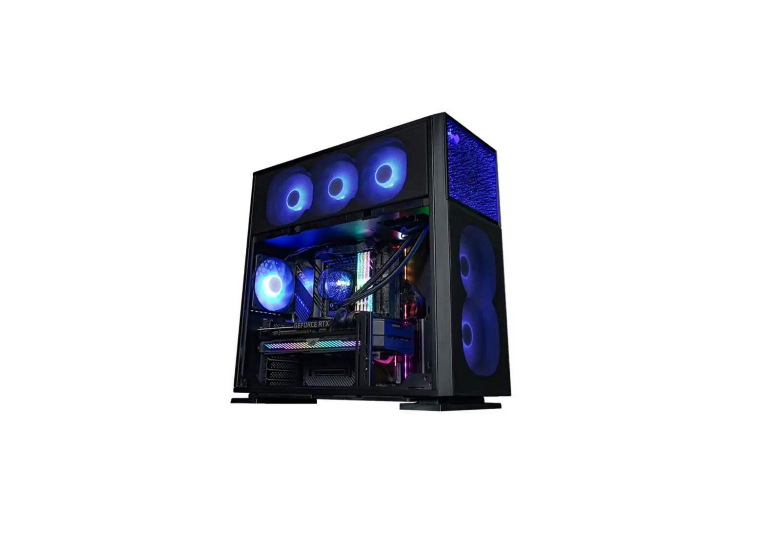
InWin N515 Gaming Chassis
Product Video Information

515/N515 Product Video

515/N515 Installation Video
Product Story
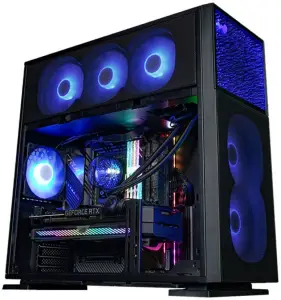
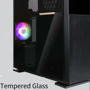
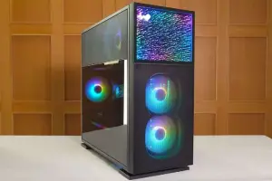
The 515 is a stunning computer chassis crafted from 1.2 mm SECC steel and tempered glass. The distinctively clean panels are complemented with mesh to increase ventilation. In addition to the 515, the N515 has a front panel showing an infinite crystal universe where light extends in all directions! Both cases are prebuilt with a LUNA addressable RGB fan that will cool your system in style!
Specifications
| Model | 515 | N515 |
| Model Number | IW-CS-515BLK 1AL120 | IW-CS-N515BLK 1AL120 |
| Colors | Black | |
| Case Type | Mid Tower | |
| Materials | SECC, ABS, Tempered Glass | |
| M/B Compatibility | 12” x 13” E-ATX, ATX, Micro-ATX, Mini-ITX | |
| Expansion Slots | 7 x PCI-E | |
| Maximum Compatibility | VGA Card Length: 385 mm CPU Heatsink Height: 160 mm | |
| I/O Ports | 1 x USB 3.2 Gen 2×2 Type-C 2 x USB 3.2 Gen 1 HD Audio | |
| Internal Drive Bays | 2 x 3.5” / 2.5” 2 x 2.5 | |
| Thermal Solution Compatibility | Air Cooling Fans: Top: 3 x 120 mm Rear: 1 x 120 mm Bottom: 3 x 120 mm Front: 2 x 120 mm (1 InWin Luna AL120 Fan Included) Water Cooling Radiator: | |
| * Number of fans pre-installed may vary based on different regions. | ||
| Power Supply Compatibility | PSII: ATX12V – Length up to 200 mm | |
| Product Dimensions (L x W x H) | 515 x 225 x 502 mm 20.3 x 8.8 x 19.7″ | |
| Package Dimensions (L x W x H) | 610 x 572 x 335 mm 24 x 22.5 x 13.1″ | |
| Net Weight | 11.38 kg | 11.65 kg |
| Gross Weight | 13.46 kg | 13.73 kg |
* InWin products comply with RoHS regulation.
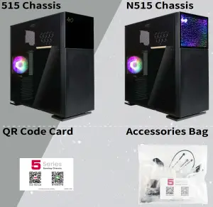
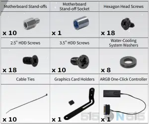
Package Contents
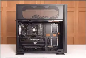
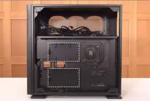
Case Structure
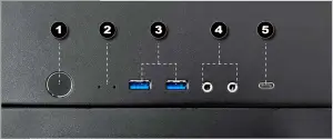
- Power Button
- Power/HDD LED Indicator
- 2 x USB 3.2 Gen 1 Ports
- Audio Ports (Earphone and Microphone)
- 1 x USB 3.2 Gen 2×2 Type-C Port


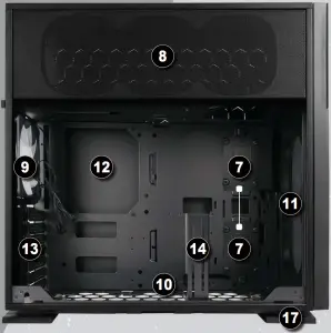
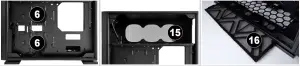
- 3.5″ / 2.5″ Drive Bay
- 2.5″ Drive Bay
- Top Fan/Radiator Mounting Area
- Rear Fan/Radiator Mounting Area
- Bottom Fan/Radiator Mounting Area
- Front Fan/Radiator Mounting Area
- Motherboard Mounting Area
- PCI-E Expansion Slot
- Graphics Card Holder Mounting Area
- Power Supply Mounting Area
- Fan Dust Filter
- Shock-Proof Stand
Cable Information
- Power Switch Cable x1

- HD Audio x1
- USB 3.2 Gen 1 x1
- USB 3.2 Gen 2×2 Type-C x1
- ARGB Cable x1

Installation Guide
(Please follow the steps to assemble)
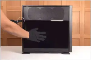
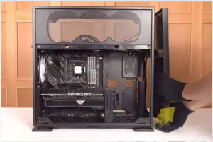
- Opening the Glass Panel
For the Tempered Glass Panel, please remove it by pressing the rear button.
Note: You will need to remove the Tempered Glass Panel first in order to remove the Mesh Fan Grill.
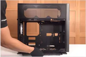
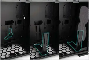
- Removing the Dust Filter and Graphics Card Holder
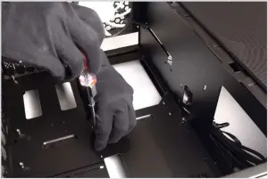
It is recommended to remove the Graphics Card Holder when installing/removing your motherboard or graphics card. - Motherboard Installation
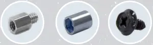
Parts Required:
Motherboard Stand-Offs,
Motherboard Stand-Off Socket
Hexagon Head Screws
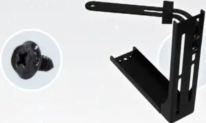
- GPU Installation
Parts Required:
Hexagon Head Screws,
Graphics Card Holder (Holder & Rubber & Bracket)
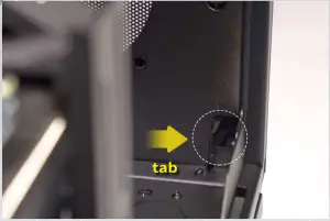
Note: Use your Graphics Card Holder to support your GPU. It is adjustable to meet your needs. - Opening the Front Panel
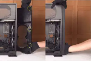
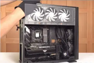
You will need to remove the Front Panel by pressing a tab to the right. Then pull the panel from beneath with your right hand. - Installing Front Fans
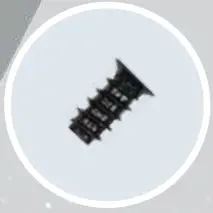
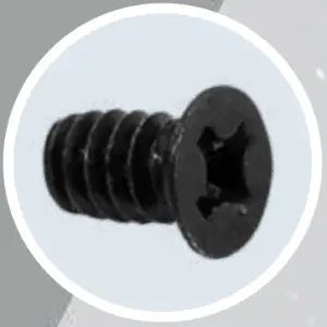
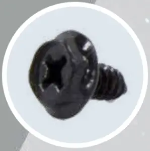
Secure the Fans with screws from the outside.
Parts Required:
Fan Screws - Closing the Front Panel
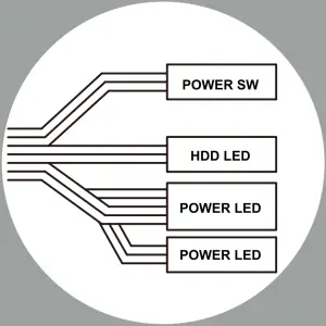
All crosses need to fit into the corresponding holes to fit neatly back into place. - Connection Cables
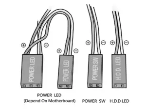
I/O Wires
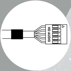
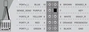
HD Audio Header
USB 3.2 Gen 1
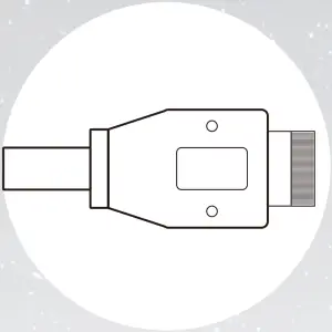
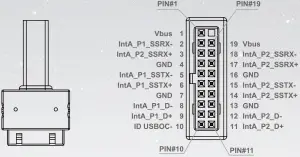
USB 3.2 Gen 2×2 Type-C

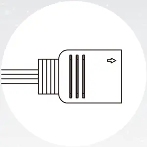
If your motherboard supports Type-C, please connect the Type-C connector with the header directly on the motherboard.Front Panel ARGB Cable
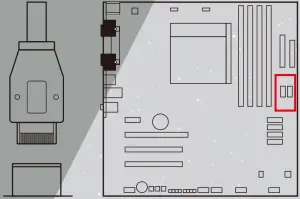
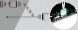
Please choose a motherboard that supports the addressable RGB lighting effect in order to light up the LED panel. Please follow the directions of the image below and insert addressable RGB cable into the 3-pin, 5V header directly on the motherboard.
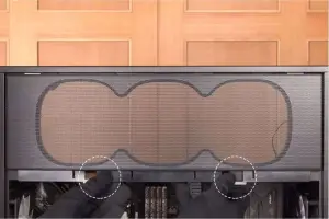
- Fan/Liquid Cooling Radiator Installation
To remove the side Mesh Fan Grill, lift up on the bottom tabs.
Note: It is recommended that you choose an AIO with tubes that are around 450 mm or more in length. The InWin BR36 & NR36 AIO are examples that would fit well. - 2.5″ Drive Bay Installation
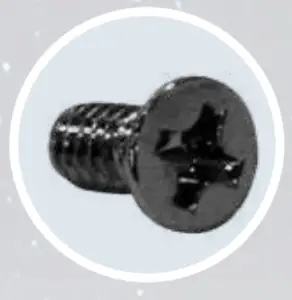
Parts Required:
2.5″ HDD Screws - 3.5″ Drive Bays Installation
Parts Required:
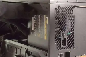
3.5″ HDD Screws - Power Supply Installation
Parts Required:
Hexagon Head Screws - Closing all Panels
- Completing Installation


Notices and Warranty
Notices
- Please follow the user manual for installation guidelines.
- When installing computer components, please use the antistatic precautions to prevent ESD (electrostatic discharge) damage. This can cause injury to the installer and/or damage to the machine. Incorrect installation may burn your motherboard and other system components.
- To avoid any damages, please do not use this product for any other purpose than its intended use.
- Any modifications may damage the product.
- Please remove all internal devices before shipping or moving. (Including power supply, hard drives, CD-ROM, motherboard and CPU, etc)
Warranty
- For more detailed warranty information, please visit the InWin retail website at www.in-win.com
- The actual product is subject to change without prior notice. In Win Development Inc. reserves the right to make any final modifications.
Copyright © 2021 In Win Development Inc. All Rights Reserved.